UINICS LV1000 Series User manual

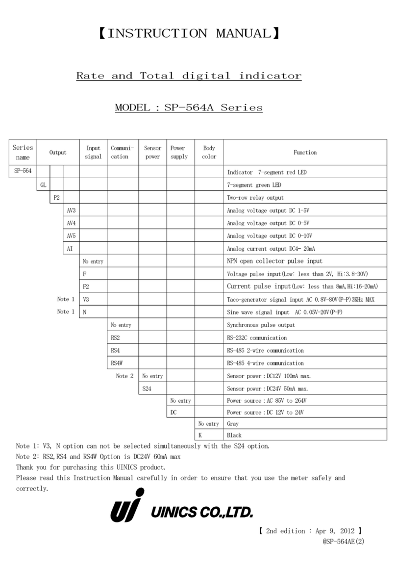
【INSTRUCTION MANUAL】
Level Meter
MODEL:LV1000 Series
Series name
Output
Input
Sensor
power
Power
Color
Cover
Function
LV1000
External input function
(Hold・Compulsion zero)
Linearization function (21 points)
2 preset outputs (c touching relay output)
2 terminal stand covers
P4
Optional 2 preset outputs
(2 normally-open relay outputs)
※P10
Optional 8 preset outputs
(NPN open collector output)
※P12
Optional 10 preset outputs
(2 normally-open relay outputs)
( 8 NPN open collector outputs
)
AI
Analog current output(DC4-20mA)
AV3
Analog voltage output(DC1-5V)
AV4
Analog voltage output(DC0-5V)
AV5
Analog voltage output(DC0-10V)
※RS4
RS-485 communication(2-wire)
※RS4W
RS-485 communication(4-wire)
A2
Analog current input(DC4-20mA)
A3
Analog voltage input(DC1-5V)
A4
Analog voltage input(DC0-5V)
A5
Analog voltage input(DC0-10V)
None
DC24V Output stabilization
( 150mA MAX )
S12
DC12V Output stabilization
( 200mA MAX )
S5
DC5V Output stabilization
( 100mA MAX )
None
AC power(AC85-264V)
DC
DC power(DC12-24V)
None
Gray
K
Black
※ The option of P10/P12 and RS4/RS4W cannot be selected at the same time.
【 The second edition 9th Mar. 2016 】
@LV1000(2)-E

Precautions
Please read this Operation Manual including the following precautions carefully to ensure safe
use of your meter.
<Caution> Do not use this product applications outside of product specifications.
<Caution> User-conducted alterations and modifications of the unit should not be performed
as they may impair functioning or cause failure and accidents.
<Caution> Direct sunshine is avoided, and ratings are used in the place of each onshime and
the place shere the be dewy occurs easily.
<Caution> Do not use it the place with the combustible gas and the ignition thing.
<Caution> Do not subject the unit to strong vibrations or shocks.
<Caution> Do not allow metallic debris, dust, or moisture to penetrate the unit.
<Caution> Always turn the power OFF before commencing any wiring work.
<Caution> Please use one which matches rating for the AC, DC power supply to a meter.
<Caution> After the power supply, it operates at once because there is no power on/off
switch for the unit.
<Caution> Do not touch the terminal while operating. It gets an electric shock.
!
!
!
!
!
!
!
!
!
!

Contents
1.Attachments and Warranty ・・・・・・・・・・・・・・・・・・・・・・・・・・・・・・・・・1
2.Specifications ・・・・・・・・・・・・・・・・・・・・・・・・・・・・・・・・・・・・・ 2-5
3.Mounting meter ・・・・・・・・・・・・・・・・・・・・・・・・・・・・・・・・・・・・・・6
4.Connecting terminal board ・・・・・・・・・・・・・・・・・・・・・・・・・・・・・・・・・7
5.Construction of input / output circuit・・・・・・・・・・・・・・・・・・・・・・・・・・・8
6.Names and functions of components on front ・・・・・・・・・・・・・・・・・・・・・・・9-11
7.The setting menu ・・・・・・・・・・・・・・・・・・・・・・・・・・・・・・・・・・・ 12-15
≪Each mode transition≫ ・・・・・・・・・・・・・・・・・・・・・・・・・・・・・・・・ 12
≪Preset value setting≫ ・・・・・・・・・・・・・・・・・・・・・・・・・・・・・・・・ 12
≪Mode setting≫ ・・・・・・・・・・・・・・・・・・・・・・・・・・・・・・・・・・・・ 13
≪Scaling setting≫・・・・・・・・・・・・・・・・・・・・・・・・・・・・・・・・・・・ 13
≪Linearization setting≫ ・・・・・・・・・・・・・・・・・・・・・・・・・・・・・・・・ 14
≪8-step preset value setting≫・・・・・・・・・・・・・・・・・・・・・・・・・・・・・ 14
≪Test mode≫・・・・・・・・・・・・・・・・・・・・・・・・・・・・・・・・・・・・・・ 15
8.Initial setting values and initialization・・・・・・・・・・・・・・・・・・・・・・・ 16-19
9.Manner of operation of set list display・・・・・・・・・・・・・・・・・・・・・・・・・・ 20
≪Calling method≫・・・・・・・・・・・・・・・・・・・・・・・・・・・・・・・・・・・・ 20
≪Method of oprating keys for setting display list≫・・・・・・・・・・・・・・・・・・・ 20
10.Scaling setting method ・・・・・・・・・・・・・・・・・・・・・・・・・・・・・・・・ 21-26
≪Calling method≫・・・・・・・・・・・・・・・・・・・・・・・・・・・・・・・・・・・・ 21
≪Programming and information lamp operation≫ ・・・・・・・・・・・・・・・・・・・・ 21-25
≪Method of operating keys for scaling setting≫ ・・・・・・・・・・・・・・・・・・・ 25-26
11.Mode setting method ・・・・・・・・・・・・・・・・・・・・・・・・・・・・・・・・・27-39
≪Calling method≫・・・・・・・・・・・・・・・・・・・・・・・・・・・・・・・・・・・・ 27
≪Method of operating key to mode setting≫ ・・・・・・・・・・・・・・・・・・・・・ 27-28
≪Contents of each mode setting≫ ・・・・・・・・・・・・・・・・・・・・・・・・・・・28-39
Mode №0 Setting the calculation function/display method/decimal point position ・・・・ 28
Mode №1 Setting the least significan digit correction/domain“0”indication function・ 29
Mode №2 Setting the sampling time・・・・・・・・・・・・・・・・・・・・・・・・・・・ 29
Mode №3 Setting the zero point adjustment and external input ・・・・・・・・・・・・ 30-31
Mode №4 Preset output:Common setteing (1) ・・・・・・・・・・・・・・・・・・・・・・ 31
Mode №5 Preset output:Common setteing (2) ・・・・・・・・・・・・・・・・・・・・・・ 32
Mode №6 Preset output:Setting the OUT1・・・・・・・・・・・・・・・・・・・・・・・・ 33
Mode №7 Preset output:Setting the OUT2・・・・・・・・・・・・・・・・・・・・・・・・ 34
Mode №8 Preset output:Setting the OUT3(Optional setting)・・・・・・・・・・・・・・ 34
Mode №9 Preset output:Setting the OUT4(Optional setting)・・・・・・・・・・・・・・ 35
〔About the disconnection detection function〕
・
・・・・・・・・・・・・・・・・・・・・・ 35
Mode №A Analog output:Setting the output display selection/output method
(Optional setting)・・・・・36

Mode №b Setting of 8 step preset output (Optional setting) ・・・・・・・・・・・・・ 37
Mode №C Setting of communication RS-485(1)(Optional setting) ・・・・・・・・・・・・ 38
Mode №d Setting of communication RS-485(2)(Optional setting) ・・・・・・・・・・・・ 39
12.Mode protect function ・・・・・・・・・・・・・・・・・・・・・・・・・・・・・・・・・・ 40
≪The key operation of mode protect≫ ・・・・・・・・・・・・・・・・・・・・・・・・ 40
13.About the zero adjustment ・・・・・・・・・・・・・・・・・・・・・・・・・・・・・・・・ 41
≪The method of zero point adjustment≫ ・・・・・・・・・・・・・・・・・・・・・・・ 41
≪How to see the deflection data of zero point adjustment≫ ・・・・・・・・・・・・・ 41
14.Linearization function・・・・・・・・・・・・・・・・・・・・・・・・・・・・・・・・・ 42-45
≪Linearization function≫・・・・・・・・・・・・・・・・・・・・・・・・・・・・・・・ 42
≪Calling method≫ ・・・・・・・・・・・・・・・・・・・・・・・・・・・・・・・・・・ 42
≪The key operation method of a linearization function≫・・・・・・・・・・・・・・・43-45
≪The example of setting of linearization≫・・・・・・・・・・・・・・・・・・・・・ 46
15.How to set the preset value・・・・・・・・・・・・・・・・・・・・・・・・・・・・・・ 47-48
≪Calling method≫ ・・・・・・・・・・・・・・・・・・・・・・・・・・・・・・・・・・ 47
≪The key operation of preset value setting≫・・・・・・・・・・・・・・・・・・・・47-48
16.The method of analog adjustment(In an option setup, an analog output contains)・・・・ 49-53
≪Calling method≫ ・・・・・・・・・・・・・・・・・・・・・・・・・・・・・・・・・・ 49
≪The key operation of analog adjustment≫ ・・・・・・・・・・・・・・・・・・・・・49-52
≪Flow chart for analog adjustment≫・・・・・・・・・・・・・・・・・・・・・・・・・・53
17.8-step preset output (Optional setting)・・・・・・・・・・・・・・・・・・・・・・・・・54
18.The method of an 8-step preset value setup (Optional setting)・・・・・・・・・・・・ 55-56
≪Calling method≫ ・・・・・・・・・・・・・・・・・・・・・・・・・・・・・・・・・・ 55
≪The key operation method 8-step preset value setup≫・・・・・・・・・・・・・・・ 55-56
19.Communication function (Optional setting)・・・・・・・・・・・・・・・・・・・・・・ 57-59
≪About a communication function≫ ・・・・・・・・・・・・・・・・・・・・・・・・・・ 57
≪About a communication operation≫ ・・・・・・・・・・・・・・・・・・・・・・・・ 58-59
20.Dimensions ・・・・・・・・・・・・・・・・・・・・・・・・・・・・・・・・・・・・・・・ 60
21.About a noise countermeasure ・・・・・・・・・・・・・・・・・・・・・・・・・・・・・・・61
22.Troubleshooting ・・・・・・・・・・・・・・・・・・・・・・・・・・・・・・・・・・・・・ 62

- 1 -
1.Attachments and Warranty
About confirmation of attachments.
When you received as a product, please confirm whether it includes the following.
(1)LV1000(The chosen specification) ・・・・・・・・・・・・・・1
(2)LV1000 Operation manual(Attachment)・・・・・・・・・・・・・1
(3)Unit label(Attachment) ・・・・・・・・・・・・・・・・・・・・1
(4)Rubber packing(Attachment) ・・・・・・・・・・・・・・・・・・1
(5)Plug male of 9D-subpins soldering type(Attachment) ・・・・・・1
〔RS4,RS4W,P10,and P12 optional, Attachment〕
(6)9D-subpin food(Attachment) ・・・・・・・・・・・・・・・・・・1
〔RS4,RS4W,P10,and P12 optional, Attachment〕
(7)Terminal stand cover ・・・・・・・・・・・・・・・・・・・・・・2
If there are the mistaking parts and the missing parts, please inform a dealer or us.
(There is a case that you don
′
t
attach by convenience.)
About a guaranteed period and a guaranteed area.
1.Guaranteed period
The period a product guarantees is 4 years from a delivered day.
2.Guaranteed area
If we trouble by responsibility in whole guaranteed period, it`s repaired without charge at our
factory.
But if a product conflicted in the following matter, it isn`t a guarantee target.
Please understand.
① Case of outside of the product specifications.
② Case of User-conducted alterations and modifications of the unit.
③ Case of besides our responsibility.
④ Case of safekeeping and transportation beyond the product specification condition.
⑤ Case of an accident.

- 2 -
2.Specifications
【 Standard specifications 】
Item Specifications
Rate mete Operation form Rate meter
Operation system A/D conversion operation. Input intervals:About 20ms
The resolution:About 1/22000 (To full scale input)
Scaling
Setting the analog is minimum / maximum input value and minimum
/ maximum value
0 adjustment function Measurement displayed + is pressing for 2 sec or
more display is adjusted to 0. (Setting mode 3)
Display accuracy ±0.1% rdg.±2digit for full scale analog input
(23℃±5℃, power on for 30 minutes or more)
Display Red LED:5 digits Character height:10mm
Indication area -9999 to 9999 (When indication overflowed,「-9999」or「9999」
flashes on and off.)
Domain”0”indicated
function
It makes between two poins arbitrarily set“0”.
(“Mode №1”It is necessary to set it in "Minimum in area
0/maximum in area 0" of the scaling setting.)
Decimal digits Displays 0 to 0.000 decimal digits (selectable)
Sampling time Rate reading averaged by 0.1-10.0 sec (selectable)
Least significant digit
Slectable: real, fixed at 0, or 0/5
Ratio Conversion method
Scaling conversion between two points indicated values at moment
of 0.0%,100.0%
Indication area
-999.9 to 999.9. 0.0 fixation of the decimal point position.
(When indication overflowed,「-999.9」or「999.9」flashes on
andoff. )
Ratio indication lamp It lights up displaying the ratio value.
(When the key is pushed,the change is rate mete)
Bar meter Display 1.6mmx0.8mm LED (16 orange LEDs, 4 white LEDs) 20 LEDs in all
White LEDs turn on at 25, 50, 75, 100%.
Scale marks 0, 25, 50, 75, 100
Display method O to 100% LEDs turn on or off
according to the rate value every
5.0%.
Over flow
Over 100.0% (over 100.1%): all LEDs will blink.
Under 100.0% (under -
0.1%): the least significant LED will
blink.
Display update time Synclonize with sampling time for the indicated value.
Linearization
Function selection
Effective/invalidity of the linearization function is selected.
(Slects it by“Mode №0”)
※ It exists also in the ratio indication.
Setting method
Straight line approximate value(21ch is possible to set it)
The input of each ch can be arbitrarily set by 0.00-105.00%.
The output of each ch can be arbitrarily set by -9999-99999.
(The decimal point of the output synchronizes with the decimal)
Sensor
input
A2-type Analog current input: DC4-20mA Input resistance: aprrox 250Ω
A3-type Analog voltage input: DC1-5V Input resistance: aprrox 200kΩ
A4-type Analog voltage input: DC0-5V Inpur resistance: aprrox 200kΩ
A5-type Analog voltage input: DC0-10V Input resistance: aprrox 200kΩ
Temperature
characteristic ±100ppm/℃(0-50℃)
Sensor power DC+24V(±5%) 150mA max output
Option:S12 DC+12V(±5%) 200mA max output
Option:S5 DC+ 5V(±5%) 100mA max output
ENT

- 3 -
Cisconnection detection
function
It is judged that it disconnects when becoming 「Input signal≦
-20%F.S.」 Rate mete and ratio“- - - - - blinking”
(A2,A3 type)
※ The disconnection detection can be output from OUT4(Option)
EXT. input
EXT input function
Hold/peak hold/bottom hold/width of input/0 adjustment
function.(“mode №3” selectable)
The rear terminal board (6-7) is ON. 50mS or more is ON.
(HD turning on the lamp)
Input NPN open collector pulse input or ground contact.
Preset
output
Output terminal Output terminals no.1-2-3 (OUT1),14-15-16 (OUT2)
Comparative system Upper limit, lower limit (immediately) and lower limit
(delay). (selectable)
Output mode Comparison, maintenance,(selectable)
Output selection Function stop, Rate mete, Raito,(selectable)
Preset value setting The presetting program mode setting is also selectable.
Output judgment Judgment output is compared with the indication value by
preset value.
Output circuit
Tow-row relay 1c output
[ Control capacity / Maximum permissible power ]
AC125V 0.6A (Resistance load)
AC250V 0.3A (Resistance load)
DC 30V 2A (Resistance load)/60W MAX
[ The maximum control current ]
2A MAX
※ Can be used within control current 2A and control capacity
/ permissible power.
Output indication During presetting output, the OUT1 and OUT2 LED are activated
Output reset
The key to the pushed for 2 sec or more.
Hysteresis setting 0-3999 (4 digits to disregard decimal point)
Hysteresis operation Invalid or selects it from effective.
※ When the output mode is only“Compareson”,it operates.
Preset output state
distinction time
It outputs it continuing set time (0.0-99.9 sec) after it
enters the output area at the output area.
Data backup Each mode stting value is memorized by FRAM
(The memory number of times is within 100,000 times,
About 10 year safekeeping.)
Others
Mode protect function Changes by mode protect function setting.
“L-oFF”is possible to change by setting.
“L-on”is not possible to change by setting.
Warm up time After turning on the power, more than 30 minutes.
Power source AC85-264V (50/60 Hz)
DC-type DC12-24V (±10%)
Power consumption Approx. 23VA
DC-type Approx. 10W
Temperature/humidity
conditions
0-50 ℃, 30-80 %RH (Non-condensing)
Weight/dimensions Approx. 370g, W96×H48×D130mm
Material of the case ABS
Color Gray
K-type Black
Protection class IP66
/75VA MAX
RST

- 4 -
【Optional specification】
<Preset output +2 step output :option P4>
Preset
output
+
2 step
output
Output terminal Output terminals no.4-5 (OUT3),17-18 (OUT4)
Comparative system Upper limit, lower limit (immediately) and lower limit
(delay). (selectable)
Output mode Comparison, maintenance,(selectable)
Output selection Function stop, Rate mete, Raito,(selectable)
※ Only OUT4 can select the disconnection detection.
Preset value setting The presetting program mode setting is also selectable.
Output judgment Judgment output is compared with the indication value by
preset value.
Output circuit Tow-row relay 1a output
[ Control capacity / Maximum permissible power ]
AC125V 0.6A (Resistance load)
AC250V 0.3A (Resistance load)
DC 30V 2A (Resistance load)/60W MAX
[ The maximum control current ]
2A MAX
※ Can be used within control current 2A and control
capacity / permissible power.
Output indication During presetting output, the OUT3 and OUT4 LED are
activated
Hysteresis setting 0-3999 (4 digits to disregard decimal point)
Output reset The key to the pushed for 2 sec or more.
Hysteresis operation Invalid or selects it from effective.
※ When the output mode is only“Compareson”,it operates.
Preset output state
distinction time
It outputs it continuing set time (0.0-99.9 sec) after it
enters the output area at the output area.
<Preset output +8 step output :option P10>
Preset
output
+
8 step
output
Output terminal D-sub 9 pin connector
Output from 2-9(Pin1 is GND)
Comparative system Upper limit, lower limit (immediately) and lower limit
(delay). (selectable)
Output mode Comparison, maintenance,(selectable)
Output selection Function stop, Rate mete, Raito,(selectable)
Preset value setting The 8 step presetting program mode setting is also
selectable.
Output judgment Judgment output is compared with the indication value by
preset value.
Output circuit 8 step NPN open collector output
Maximum: DC30V 50mA max
Output reset The key to the pushed for 2 sec or more.
< Preset output + 10 step output specification:option P12 >
Becames a composition of Preset output + 2 step output + 8 step output
Please refer to the specification of option P4, P10.
/75VA MAX
RST
RST

- 5 -
<Analog output :Option AV3-5,AI>
Analog
output
Output terminal Output terminals no. 19-20
Output setting Indicated value with minimum, maximum analog output is set.
Voltage
output
AV3 DC1-5V Loadimpedance 2kΩ or more
AV4 DC0-5V Loadimpedance 2kΩ or more
AV5 DC0-10V Loadimpedance 2kΩ or more
Corrent
output AI DC4-20mA Loadimpedance 500Ω or less
Output timing “The indication value synchronizing” “Sanpling time
synchronizing” (selectable)
Output accuracy Within ±0.1% F.S. for indicated value (23±5℃, power on f
or 30 minutes or more)
Temperature caracteristic
±50ppm/℃ (0-50℃)
Output response Approx 1ms(
But,an output change is time until the 90% arrival)
Maximum output resolv
ing ability
D/A conversion operation
・ DC1- 5V : Maximum 19999 resolution
・ DC0- 5V : Maximum 19999 resolution
・ DC0-10V : Maximum 19999 resolution
・ DC4-20mA : Maximum 19999 resolution
Caution) The analog output (AV, AI) renge is internal logic
is set. Please do not change.
Output area 0%-102.4%
・ AV3 : 1-5.096V
・ AV4 : 0-5.12V
・ AV5 : 0-10.24V
・ AI : 4-20.384mA
※ Compulsorily outputs it by 0% or 102.4% when becoming an
over indication“-9999 Flushing”or“9999 Flushing”
The output inclination to scaling depends on the scaling
setting.
<RS-485 communication :Option RS4, RS4W>
RS-485
Communi
cation
Signal terminal Communication from D-sub connector (9 pin)
Signal level In accordance with IEE RS-485
Synchronous method RS4 : 2-wire system Half duplex communication
RS4W: 4-wire system Half duplex communication
Baud rate 2400/4800/9600/19200 bps (Selectable)
Start bit 1 bit
Stop bit 1 bit
Data bit 7/8 bits (Selectablu)
Parity bit Odd/Even/None (Selectablu)
Unit (ID) nomber 00-99
Communication system Communication is controlled by command
Communication data Writing the indicated value, Reading and writing setting va
lues of preset output.
Maximum connection 32
Communication code ASCII code

- 6 -
130 or more
+0.5
-045
+0.8
-092
(Unit:mm)
70 or more
Fitting for fixing the body
Driver
Packing
Mater
Plate
3. Mountin meter
How to mount indicator (meter)
1. Cut the panel to insert the indicator (meter)
from the front.
Panel cutout dimensions
Fig.1
2.
Please push the Fitting for fixing the body.
Into a right and left both sides of the meter.
Fig.2
3.
Slide in the rear side (terminal stand side) as for
the Fitting for fixing the body.
It turns a screw by the driver.
The meter is fixed (right and left both sides)
Fig.3
1.Please install it horizontally.
2.Fit the body on to a panel 1.0-4.0mm in thickness.
3.Please do not tighten the screw of the mounting bracket too much.
(The case might be damaged when tightening too much.)

- 7 -
4. Connecting terminal board
≪Terminal boards≫ Fig.4
[EXT.input (Terminal board 6-7)]
Hold/Peak hold/bottom hold/width of input/0 adjustment function.
Mode setting (P.30-31 “mode3”) (selectable)
[8 step preset output(option)]
Please refer to P.54“17. 8 step preset output”for the pin layout and the circuit specification.
[Communication function(option)]
Please refer to P.57-59“19.Communication function”for the pin layout and the circuit
specification.
≪Sensor boads≫
1)2-wire transmission type sensor Fig.5 2)3-wire type sensor Eig.6
3)4-wire type sensor Fig.7
<Caution>
The input circuit is connected with the sensor power GND inside.
Please carry out floating of the input circuit, and when used, consult to our company.
!

- 8 -
5.Construction of input / output circuit
〔1〕Analog input Fig.8
〔2〕EXT. input Fig.9
〔3〕Analog output
Voltage output (AV) Fig.10 Current output (AI) Fig.11
〔4〕Preset output
Relay output(1c Point of contact)Fig.12 Relay output(1a Point of contact)Fig.13

- 9 -
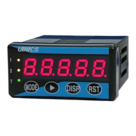
6.Names and functions of components on front
Fig.14
① Display unit(Rad)(A-E)
1)Measurement value indicated at the time of measurement state.
2)Initialization
A-E:「 (A,B are blanks.), 」is indicated.
3)Set list display
A :Blank
B-E:「 (Pr.St), (Md.St), (SC.St),
(Ln.St), (P8.St)」is indicated.
4)Mode set, Adjusting the analog mode set.
A :Setting No is indicated.
B-E:Setting value is indicated.
5)Scaling value, Preset value, 8 step preset value, setting.
A :“-”,“0-9”is indicated.
B-E:“0-9”is indicated.
6)Linearization setting.
・At the title indicated.
A-E:「 (Ln.01A)~ (Ln.21A) ,
(Ln.01b)~ (Ln.21b)」is indicated.
・At the setup indicated.
A :“0-1”is indicated. (Ln.01A ~Ln.21A setting state)
:“-”,“0-9”is indicated.(Ln.01b ~Ln.21b setting state)
B-E:“0-9”is indicated.
7)Mode protect setting.
A-E:「 , 」is indicated.
② Bar meter(Orange, White)
Measurement state:LEDs (0 -100%) turn on or off according to the rate value every 5.0%.
Over 100.0% (over 100.1%): all LEDs will blink.
Under 100.0% (under -0.1%): the least significant LED will blink.
Setting state:All LEDs turn off.
③-⑥ Preset output lamp(Red)(1-4)
Measurement state:It lights up OUT1-4 at the presetting output.
Setting state:The output lamp setting it now lights when the preset value is set.
The output lamp lights or blinks by each setting when scaling is set.
The output lamp lights or blinks by each setting when
8 presets value is set.
⑦ EXT. input lamp (Green)(HD)
Measurement state:The EXT.input (the terminal board 6-7th) is input, it lights.

- 10 -
⑧ Ratio lamp (Green)(%)
Measurement state:It lights up at the ratio indicated value.
Setting state:The output lamp lights or blinks by each setting when scaling is set.
:The output lamp lights by each setting when
8 presets value is set.
⑩ Shift key
Measurement state:Preset display is adjusted “0”when pushing with for 2 sec or more.
(When zero adjustment function is made sffective,
it is necessary to set mode No.3.)
:When pressing for 2 sec or more, the deflection data of the zero point
adjustment.
Set list display:It shifts to the setting displayed in the display unit.
Setting state:Moves the flash figure when each setting, to the right.
:When is pushed while pushing when the mode is set,
the Mode No. (Display unitA) is changed in the descending order.
(d→C→b→A・・・1→0→d→C→b・・・)
:When is pushed while pushing when linearization is set,
the title is changed in the descending order.
(Ln.21b →Ln.21A → Ln.20b→ ・・・ → Ln.01A → Ln.21b → ・・・)
:Present bit value are indicated at the time of analog input adjustments
mode setting.
⑩ Down key
Initialization state:The display becomes “ “ if is pushed in the state
of the initialization selection (“ ” display),
and it initializes it.
It changes into the measurement operation afterwards.
Measurement state:It uses it when the mode protecting function is called, and it changes.
(2 sec or more: Mode protecting display → 8 sec or more:
Mode protecting changes .)
Setting state:Changes the value of the blinking digit during setup procedures.
Each time the key is pressed, the number goes down.
:When analog output adjusted, the output bit value goes down.
⑪ Mode key
Power on state:When a power on while is pushing down , a test mode functions.
(A stop of the test mode function is power off.)
Measurement state:When is pressing for 2 sec or more, setting list display is called.
Set list display:The setup data display is changed.
(Pr.St → Md.St → Sc.St → Ln.St → P8.St → Pr.St → ・・・)
Setting state:Mode No.(indicator A) is switched.
(0→1→2→3・・・C→d→0→1→2・・・)
:When the scaling value is set, a set content is changed.
:When the preset value is set, OUT1 to OUT4 are switched.
Mode
Mode
Mode
Mode
Mode

- 11 -
:When the 8 preset value is set, ch1 to ch8 are switched.
:When the title display of the linearization setting, the title display is changed.
(Ln.01A → Ln.01B → Ln.02A → ・・・ → Ln.21b → Ln.01A → ・・・)
:When the content of linearization set set is displayed,it changes to the title
display.
:When the analog adjustment mode set, analog adjustment No.(indicator A) is
switched. (Blank →A→b→C→d→Blank →A→b)
⑫ Up key
Measurement state:Present display is adjusted“0”when pushing with for 2sec ormore.
(When zero adjustment function is made effective, it is necessary to
setmode No.3.)
:When is pressing for 5 sec or more, while is pushing down ,
The measurement is restarted from the state of the power on.
(*1 Operation reset)
Setting state:Changes the value of the flashing digit during setup procedures.
Each time thekey is pressed, the number goes up by one.
:When analog output adjusted, the output bit value goes up.
⑬ Enter key
Power on state:When a power on while is pushing down ,“ ”display, and it
enters the state of the initialization selection.
Measurement state:The rate mete and the ratio are changed.
(It is necessary to set the Mode No.0)
:When is pressing for 5 sec or more, while is pushing down
The measurement is restarted from the state of the power on.
(*1 Operation reset)
Set list display:Shifts to the measurement.
Setting state:A set value is registered when each setting it, and it shifts to a set list.
:When the analog adjustment mode is set, the setting value is registered.
⑭ Reset key
Power on state:When a power on whili is pushing down ,analog adjustment mode functions.
Initialization state:When initialization is selected( display)is pushing down ,
It shifts to the measurement operation without initializing.
Measurement state:When pressing for 2 sec or more, resets the presetting output
Setting state:During setup procedures the display returns to the set list display,
without registering.
:When is pressing for 2sec or more, when analog adjusting it,
returns to the measurement.
*1 Operation reset
When + is pressing for 5 sec or more while displaying the measurement,
the measurement is started from the state at power on.
Please try for the unstable operation stc.Noise etc.
ENT
RST
ENT
RST
ENT
ENT
ENT
RST
RST

- 12 -
7.The setting menu
≪ Each mode transition ≫
≪ Preset value setting ≫

- 13 -
≪Mode setting≫
≪Scaling setting≫

- 14 -
≪Linearization setting≫
≪8 step preset value setting≫

- 15 -
≪Test mode≫

- 16 -
8.Initial setting value and initialization
If the specifications desired by the user are requested prior to shipment,
the meter will be set these settings.
Otherwise, the regular factory settings are shown below.
Value setting of each Mode Table 1
Mode
Initial setting Notes Set item
A B C D E B C D E
0.
0 - - - Setting the calculation function
0 - - - Setting the display methed
0 - - - Setting the decimal point
1.
0 - - - Setting the least significant digit
0 - - - Setting the area“0”indication function
2.
1.
0 - - Setting the sampling time
3.
0 - - - Setting the zero point adjustment
0 - - - Setting the EXT input
4.
0 0.
0 - Setting the preset output common(1):
Preset output state distinction time
5.
0 0 0 0 Setting the preset output common(2):
Hysteresis value
6.
0 - - - Setting of OUT1:Output display selection
0 - - - Setting of OUT1:Upper limit, lower limit
0 - - - Setting of OUT1:Output mode
0 - - - Setting of OUT1:Hysteresis operation
7.
0 - - - Setting of OUT2:Output display selection
0 - - - Setting of OUT2:Upper limit, lower limit
0 - - - Setting of OUT2:Output mode
0 - - - Setting of OUT2:Hysteresis operation
8.
0 - - - Setting of OUT3:Output display selection
0 - - - Setting of OUT3:Upper limit, lower limit
0 - - - Setting of OUT3:Output mode
0 - - - Setting of OUT3:Hysteresis operation
9.
0 - - - Setting of OUT4:Output display selection
0 - - - Setting of OUT4:Upper limit, lower limit
0 - - - Setting of OUT4:Output mode
0 - - - Setting of OUT4:Hysteresis operation
A.
0 - - - Analog output:Output display selection
1 - - - Analog output:Output circuit
b.
0 - - - Setting of 8 step preset output:Output
display selection
0 - - - Setting of 8 step preset output:Upper
limit, lower limit
0 - - - Setting of 8 step preset output:Output mode
C.
1 - - - Setting the network transmission RS-485(1):
Deta bit
0 - - - Setting the network transmission RS-485(1):
Parity bit
2 - - - Setting the network transmission RS-485(1):
Transmission rate
d.
0 0 - - Setting the network transmission RS-485(2):
Transmission ID No
1 - - - Setting the network transmission RS-485(2):
Sending and receiving change time
Table of contents
Other UINICS Measuring Instrument manuals
Popular Measuring Instrument manuals by other brands

Satec
Satec PM172EH Series reference guide

Targus
Targus AMP21AP user guide

Agilent Technologies
Agilent Technologies 8711C Service guide

Analytik Jena
Analytik Jena SPECORD 200 PC operating manual

Rohde & Schwarz
Rohde & Schwarz ZNB user manual

Endress+Hauser
Endress+Hauser HART Proline Promag 51 operating instructions