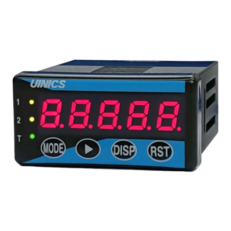
UINICS SP-564A Series User manual

Note 2
Note 1
Note 1
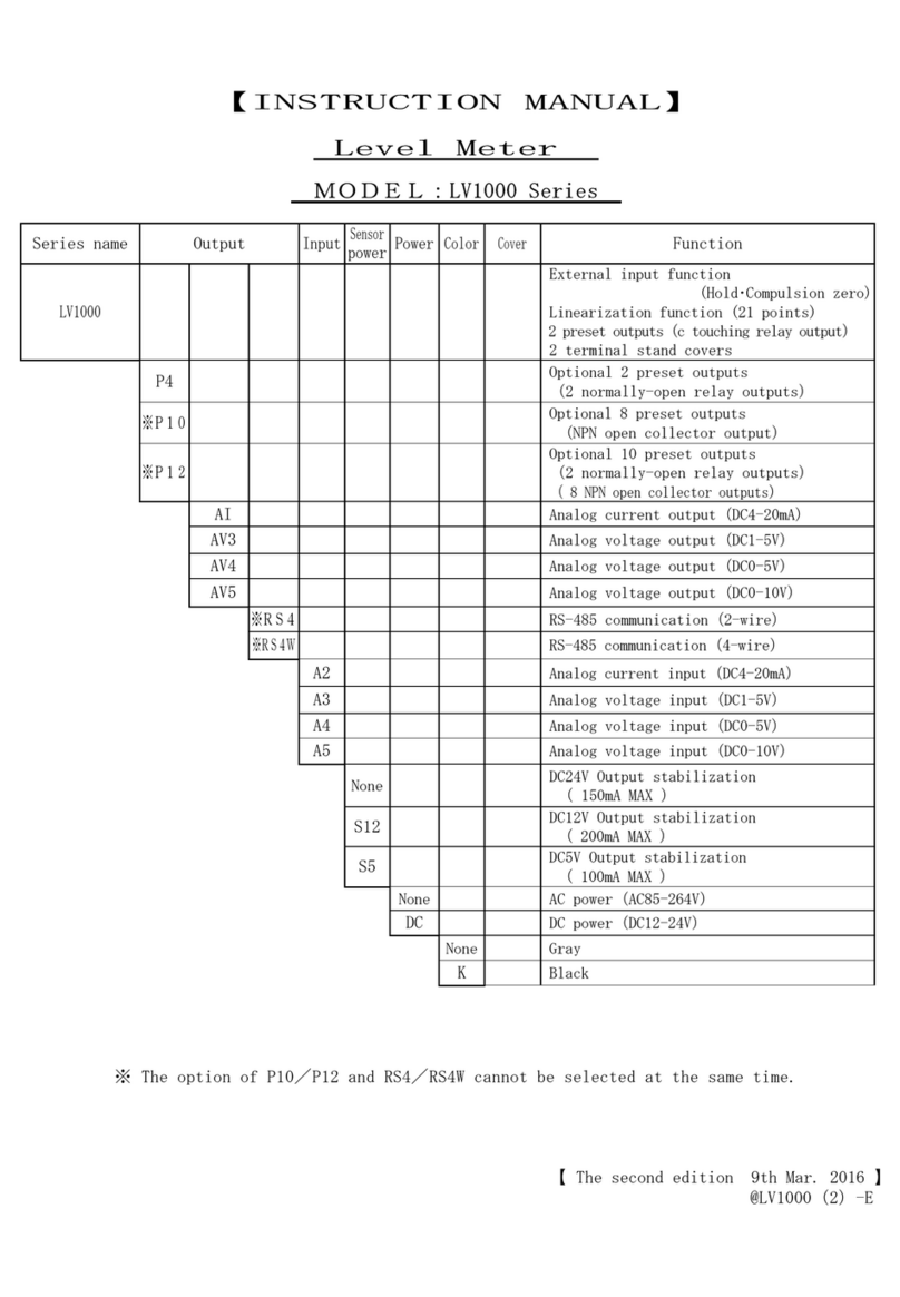
【INSTRUCTION MANUAL】
Rate and Total digital indicator
MODEL:SP-564A Series
Series
name
Output Input
signal
Communi-
cation
Sensor
power
Power
supply
Body
color Function
SP-564 Indicator 7-segment red LED
GL 7-segment green LED
P2 Two-row relay output
AV3 Analog voltage output DC 1-5V
AV4 Analog voltage output DC 0-5V
AV5 Analog voltage output DC 0-10V
AI Analog current output DC4– 20mA
No entry
NPN open collector pulse input
F Voltage pulse input(Low: less than 2V, Hi:3.8-30V)
F2 Current pulse input(Low: less than 8mA,Hi:16-20mA)
V3 Taco-generator signal input AC 0.8V-80V(P-P)3KHz MAX
N Sine wave signal input AC 0.05V-20V(P-P)
No entry
Synchronous pulse output
RS2 RS-232C communication
RS4 RS-485 2-wire communication
RS4W RS-485 4-wire communication
No entry
Sensor power:DC12V 100mA max.
S24 Sensor power:DC24V 50mA max.
No entry
Power source:AC 85V to 264V
DC
Power source:DC 12V to 24V
No entry
Gray
K
Black
Note 1: V3, N option can not be selected simultaneously with the S24 option.
Note 2: RS2,RS4 and RS4W Option is DC24V 60mA max
Thank you for purchasing this UINICS product.
Please read this Instruction Manual carefully in order to ensure that you use the meter safely and
correctly.
【 2nd edition : Apr 9, 2012 】
@SP-564AE(2)

- 1 -
■ Precautions
We thank you very much for buying our products. Please read the following matters that require
attention and the contents of this booklet for safe use of the product.
! Caution
・Use a power supply voltage within the working range.
・Avoid a load exceeding the rating.
・Avoid the direct rays of the sun.
・Avoid places where inflammable gas and combustibles are present.
・Avoid temperature and humidity exceeding the rating.
・Do not apply heavy shocks or vibration to the body.
・Avoid the penetration of metal powder, dust, water, and the like into the body.
・Pay attention to an electric shock in wiring the power supply.
・Do not touch a live terminal, which is likely to cause an electric shock.
・Do not disassemble the product nor touch its inside while it is activated.
・User-conducted alterations and modifications of the unit should not be performed as they may
impair functioning or cause failure and accidents.
1. Accessories
Refer to the following items to check the accessories.
1. SP-564(according to user’s specifications)・・・1
2. Instruction manual for SP-564・・・1
3. Unit label・・・1
4. User-specified accessories.
(In the case of the absence of such specifications, these accessories are not attached.)
If accessories are insufficient, please contact with an agency or UINICS.

- 2 -
2. Specifications
Item Specifications
Operation system Periodic sampling operation (CPU)
Display 7-segment red LED(14 mm character height):6 digits
GL-type 7-segment green LED(14 mm character height):6 digits
Measuring accuracy ±0.05% rdg.±1digit
(at Sampling time for 0.5 second or more )
Scaling 9999 - 1×10⁻⁹(selectable)
Decimal digits Displays 1-4 decimal digits(selectable).
Time unit Selectable:per hour, per minute or per second
Rate sampling time Rate reading averaged by 0.1-100 sec.(selectable)
Moving average Averaged by 2 to 9 input pulses (selectable)
Auto zero time
The time(0.1-99.9 sec. selectable), following input stop,
at which the reading returns to zero.
Least significant
digit
Selectable:real, fixed at 0, or 0/5
Rate mete
Overflow
indication
Indication overflow ,0V lamp ・999999 is blinking
Accuracy ±0 (Scaling is set to 1.)
Scaling 9999 - 1×10⁻⁹(selectable)
Decimal digits
Display 1-4 decimal digits(selectable).
(Fixed decimal operation)
Overflow
indication
Indication overflow ,0V lamp is blinking
Totalizer upper
display Upper digits 7-9 display by pressing Up key.
Reset
Internal counter is reset using Reset key or input from
terminal board(50 ms or more to activate)in rear.
Input from terminal board:NPN open collector pulse input or
ground contact
Totalizer
Synchronization
pulse output
Synchronization with total reading
Synchronization output:1-4 digits (selectable)
Output width:0.01-1.99 sec. (selectable)
Signal level:NPN open collector output, rating DC30V 50mA
(max.)
※At the time of communication option(RS2,RS4,RS4W)
it does not operate.
Standard NPN open collector pulse input (10 mA min.)or ground contact
Option(F) Voltage pulse input:2.0 V or lower for LOW, 3.8-30 V for HI
Option(F2) Current pulse input:8 mA or lower for LOW, 16-20 mA for HI
Option input(V3) Taco-generator signal input AC 0.8V~80V(P-P)3KHz MAX
Option input(N) Sine wave signal input AC 0.05V~20V(P-P) 3KHz MAX
Input response
frequency
(at 50% duty)
LOW:0.01Hz - 50Hz:It does not accept noise element of
higher frequency.
MID:0.01Hz – 1kHz
HI:0.01Hz - 10kHz:It responds to higher frequency.
Sensor power DC+12V (±10%)100mA max. output(stabilized)
Sensor
input
S24-type DC+24V (±10%)100mA max. output(stabilized)
※RS2,RS4 and RS4W Option is 60mA max

- 3 -
Input NPN open collector pulse input or ground contact
Indicator
change
When specified, input from the rear terminal board changes
indicator(Rate meter or Totalizer)
Sensor input
deactivation
When specified, input from the rear terminal board deactivates
sensor input.
EXT.
input
Reading hold
input
When specified, input from the rear terminal board causes the
current reading to go on “hold”.
Power source AC 85-264 V
DC-type DC 12-24 V(±10%)
Power consumption Approx. 19VA
Temperature/
humidity conditions
0-50 ℃, 30-80 %RH(Non-condensing)
Weight/dimensions Approx. 350 g, W96×H48×D130 mm
Body color Gray
K-type Black
Others
Protection class IP66
《 Alarm output:P2-type 》
Mechanism Judged against upper and lower limits(Selectable).
Alarm disable time
interval
The alarm output function is disabled for the specified time
interval following power ON or reset.
Output system Two-row relay output
Rating:DC 30 V 1 A, AC 125 V 0.3 A
Output indication During alarm output, the OUT1 and OUT2 LEDs are activated.
Output reset Alarm reset using Reset key or input from terminal board.
50 ms or more to activate.
《 Analog output:AV-type / AI-type 》
Voltage output (AV3) DC 1-5 V Load resistance:2kΩ or above
Voltage output (AV4) DC 0-5 V Load resistance:2kΩ or above
Voltage output (AV5) DC 0-10 V Load resistance:2kΩ or above
Current output (AI) DC 4-20 mA Load resistance:500Ω or under
Output accuracy Within ±0.2 %F.S. for indicated value (23 ℃)
Variation due to
temperature fluctuation
±100 ppm/℃
Output update Less than about 20 ms
Output response About 40 ms (Analog change time 0 %- 90 %)
Max Output resolution 12-bit D/A conversion operation
AI
DC4-20mA
: 4000 resolution
AV3 DC1-5V : 4000 resolution
AV4 DC0-5V : 4000 resolution
AV5 DC0-10V
: 4000 resolution
※Maximum output area:It's possible to output to 102.3%
to the maximum of each output.
※
An analog output is outputting calculation to the indication value
shown to 7segment LED. Therefore the resolution sometimes falls
from 4000 by setting of Mode No. ”C” and ”d”.

- 4 -
《 RS-232C communication:RS2-type 》
Signal standards In accordance with EIA RS-232C standards(Serial signal)
Synchronous method Asynchronous
Baud rate 1200bps / 2400bps / 4800bps / 9600bps(Selectable)
Start bit 1 bit
Stop bit 1 bit
Data bit 7 bits / 8 bits(Selectable)
Parity bit Odd / Even / None(Selectable)
Unit(ID)number 00-99
Communication system Communication is controlled by command.
《 RS-485 communication:RS4-type / RS4W-type 》
Signal standards 2-wire half duplex transmission(RS4-type)
4-wire half duplex transmission(RS4W-type)
Signal level In accordance with IEE RS-485
Synchronous method Asynchronous
Baud rate 1200bps / 2400bps / 4800bps / 9600bps(Selectable)
Start bit 1 bit
Stop bit 1 bit
Data bit 7 bits / 8 bits(Selectable)
Parity bit Odd / Even / None(Selectable)
Unit(ID)number 00-99
Communication system Communication is controlled by command.

- 5 -
3. Mounting meter
How to mount indicator (meter)
1. Cut the panel to insert the indicator (meter) from the front.
Panel cutout dimensions
Fig.1
Unit:mm
2 Please push the Fitting for fixing the body.
Into a right and left both sides of the meter.
Fig.2
3. Slide in the rear side (terminal stand side)
as for the fitting for fixing the body.
It turns a screw by the driver.
The meter is fixed (right and left both sides)
Fig.3
1. Please install it horizontally.
2. Fit the body on to a panel 1.0-4.0 mm in thickness.
3. Please do not tighten the screw of the mounting bracket too much.
(The case might be damaged when tightening too much.)
92 -0
+0.8
Fitting for fixing the body
Driver
Packing
Meter Installation board

- 6 -
4.Names and functions of components on front
Fig.4
① Display
1) Display indicates the rate reading or the cumulative total reading.
2) The following displays appear in the setup mode.
A,B・・・・・Mode No.
C-F・・・・・Mode setting
3) Setting value is indicated while each setting up(preset value, offset value).
② Rate meter lamp ( RA )
The rate meter lamp is activated when rate reading is indicated.
③ Totalizer lamp ( TO )
The totalizer lamp is activated when total reading is indicated.
④ EXT. input lamp ( HD )
The EXT. input lamp is activated when terminal No.4 and No.6 is shorted.
⑤ Overflow lamp ( OV )
The overflow lamp is blinking activated when the total exceeds.
⑥ Alarm output OUT1 lamp
The alarm output lamp is activated when the alarm is outputted.
⑦ Alarm output OUT2 lamp
The alarm output lamp is activated when the alarm is outputted.
Indicate
Output
HD
1
TO OV
2
ENT
RST
RA
Mode
Display
AB
1
C D E
7
6
3
2
8
9
F
4
5

- 7 -
⑧ Mode key ( Mode )
The Mode key is used to call up or switch between various settings.
1) Mode Activated for 2 sec. or more ・・・ calls up mode setting.
(Press MODE → Mode No. switchover)
2) Mode + ∧ Activated for 2 sec. or more ・・・ calls up offset value setting.
3) Mode Activated for 2 sec. or more ・・・ calls up alarm output preset value setting.
(Press MODE → OUT No. switchover)
⑨ Up key ( ∧ )
1) When the total exceeds 6 digits(999999), the overflowed upper 3 digits are displayed
while this key is pressed.
2) Changes the value of the blinking digit during setup procedures.
Each time the key is pressed, the number goes up by one.
⑩ Down key ( )
1) Activated for 2 sec or more ・・・
Mode protect ON “L-ON”
Mode protect OFF “L-OFF”
2) Changes the value of the blinking digit during setup procedures.
Each time the key is pressed, the number goes down by one.
⑪ Shift key ( )
・Shifts the blinking indication to the digit to the right during setup procedures.
⑫ Enter key ( ENT )
1) Indicator(Rate meter or totalizer)is switched. ※Refer to Mode 06.
2) During setup procedures, it is used to register the setting and to return the display
to the readings.
⑬ Reset key ( RST )
1) Resets the totalizer without interrupting or resetting the rate reading.
It also resets the alarms.
2) During setup procedures:The display returns to the readings, without registering.

- 8 -
5.Connecting terminal board
Fig.6
Fig.5
※ RS-232C/RS-485/RS-485W communication type:Refer to fig.5. (Terminal No.1-4)
There is not the EXT. input the synchronization pulse output when select a communication type.
Wiring precautions
! Caution
・Always turn the power off before commencing any wiring work.
・Please confirm the specification.
・Confirmation of power supply input
Confirm the input voltage specification (AC or DC) once again. Pay much attention to this matter.
If this is not right, a protective part and the like may be damaged.
・For DC power supply input
If + and - are connected reversely, the internal protective circuit will function to stop
the reverse current. In this case, disconnect the wires, and after about 30 seconds, connect
the wires to + and - correctly. The system will work normally.
・Since the input and output wirings differ depending on the type of the sensor, make wiring work
with the next-mentioned diagrams (Figs 7 to 9).
・Tighten the screw of the terminal boards securely.
・Use the terminal No.7 – 10 as power supply for the sensor. Do not use these terminals for
other things.

- 9 -
78910
GND +12V IN
(+24V)
Sensor
7 8 9 10
GND +12V IN
(+24V)
Sensor connection
A)Pulse output 2-wire type sensor Fig.7 B)Pulse output 3-wire type sensor
Fig.8
Proximity sensor
Encoder
C)Ground contact output sensor D)Tacho-generator signal/
Fig.9 Sine wave signal output sensor
Fig.10
E)Current pulse input F) Current pulse input
( 2-wire pulse sensor ) Fig.11 ( 3-wire pulse sensor ) Fig.12
67 8 9
Tacho-generator signal
Sine wave signal
Proximity
senso
r
78910
GND +12V IN
(+24V)
Sensor
+
-
78910
GND +12V IN
(+24V)
Sensor
-
+
OUT
7 8 9 10
GND +12V IN
(+24V)

- 10 -
6. Construction of input circuit
[1] Pulse sensor input
NPN open collector pulse input
Fig.13
Voltage pulse input
Fig.14
[2] Tacho-generator signal input/ Sine wave signal input
Fig.15
[3] Reset input
Fig.16
・Sensor power DC12V(standard):R1 = 2.2kΩ
・Sensor power DC24V(S24 type):R1 = 3.9kΩ

- 11 -
[4] EXT. input Fig.17
・Sensor power DC12V(standard):R2 = 2.2kΩ
・Sensor power DC24V(S24 type):R2 = 3.9kΩ
7. Setting the dip switch
Fig.18
The input response frequency is selected by setting the dip switch.
Table 1
SW1-1 SW1-2 SW1-3 SW1-4 OFF ⇔ ON
open collector pulse ON - - -
Voltage pulse OFF - - -
Input frequency (Low) - - OFF ON
Input frequency (Mid) - - ON OFF
Input frequency (Hi) - - OFF OFF
1
2
3
4
The black square indicates
switch position.
LOW:0.01Hz - 50Hz
MID:0.01Hz - 1kHz
HI :0.01Hz - 10kHz
The regular factory settings are shown in the diagram in the upper right.

- 12 -
8. Test mode

- 13 -
9. Initial setting values and initialization
If the specifications desired by the user are requested prior to shipment, the meter will be set
these settings. Otherwise, the regular factory settings are shown below.
1.Value setting of each Mode Table 1
2. Preset value setting of each alarm output Table 2
Initial setting Notes
Alarm
No. A B C D E F A B C D E F
OUT1 9 9 9 9 99
OUT2 9 9 9 9 99
3. Offset value setting(Totalizer) Table 3
Initial setting Notes
Offset A B C D EFABCDEF
Indication 0 0 0 0 0 0
Initialization:Power on Enter key being pressed to initialize the settings.
After the initialization, the set values will be as shown in Table 1-3.
Note:Since an initialization changes all existing setting values to the initial setting values,
be sure to record all the setting values before an initialization.
※ In case the computer froze when unusual functioning occurred with the normal operation,
initialize according to the above procedure and set the desired value again.
Mode
No.
Initial setting Note
AB C D E F C D E F
01. 1 0 0 0
02. 3 0 1 1
03. - 0 2. 0 -
04. - - - 0 - - -
05. - 0 2. 0 -
06. - - 0 0 - -
07. 1 0 0 0
08. 3 0 0 0
09. - 0 - 0 - -
10. 1 0 0 0
11. 0 0. 0 5
12. - 0 - 0 - -
13. 0 0 0 0
14. 0 0 0 0
15. 0 1 0 3
16. 0 0 - 0 -

- 14 -
10. Setting the mode
・Calling up and modifying the mode setting
When a mode is set, operate each key according to the following table.
Operating key Display unit Operation procedure
MODE + >
A B C D E F
0 1. 1 0 0 0
↑
Mode No.
While holding down the MODE key, press the
> key for 2 seconds or more.
“0 1 ” appears in displays A-B and the value
setting
for mode 01 is shown.
∧
A B C D E F
0 1. 1 0 0.0
↑
0 to 9
Change the blinking numeral value. Every press
raises the value by ones.
(0 → 1 → 2・・・9 → 0・・・)
∨
A B C D E F
0 1. 1 0 0.0
↑
0 to 9
Change the blinking numeral value. Every press
reduce the value by ones.
(0 → 9 → 8・・・1 → 0 →9・・・)
>
A B C D E F
0 1. 1 0 0 .0
→ → →
Change the blinking indication position (figure).
Every press moves the position to the right
by a figure.
MODE
A B C D E F
0 2. 3 0 1 1
↑
01 to 16
Change the mode number. Every press raises the
number by one. There are 16 modes in total.
When it reaches 16, it returns to 01.
(01 → 02 → 03・・・16 → 01・・・)
ENT
After adjusting the setting, make registration
with this key. It returns to the measuring mode
after registration.
RES
Even by pressing this key during the time
setting the mode, it returns to the measuring
mode. Pay attention to the fact that the set
data is not memorized.
Note : In case you change mode setting, turn OFF mode protect.
If it is turned ON, change of mode setting will be made impossible.
(Refer to 27 page.)
∨ Activated for 2 sec or more ・・・
Mode protect ON “L-ON”
Mode protect OFF “L-OFF”

- 15 -
Contents of modes and setting values
Mode No. Setting of converting value (scaling)
A B C D E F
0 1.1 0 0 0
Converted value
0001~9999
(Do not set 0000)
0 1
①This mode
“
01" acts as input converter.
Mode
“
02"-C acts as magnification(EXP-value).
②With input of this converter and EXP-value, it is possible to set the
magnification per 1 pulse. This EXP-value is set with Mode
“
02" .
③For instance, with display of instant flow-rate by L/min in the use of
flow sensor of 1.234mL per 1 pulse, the following is shown.
1.234mL ⇒ 0.001234L ⇒ 1234 ×10-6
Converted to the
intended value(L)
to display Converter EXP-value
A B C D E F
Mode
“
01" 0 1.1 2 3 4
A B C D E F
Mode
“
02" 0 2.6 0 0 0

- 16 -
Mode No. EXP-value, and measurement time unit setting
A B C D E F
0 2.3 0 1 1
Display decimal point setting
0・・・ 0
1・・・ 0.0
2・・・ 0.00
3・・・ 0.000
4・・・ 0.0000
measurement time unit
0 ・・・ per Hour
1 ・・・ per Minute
2 ・・・ per Second
Display condition for last figures
0 ・・・ real display
1 ・・・ "0" fixed
2 ・・・ only "0" or "5" display
EXP-value
0-9
0 2
This mode
“
02" -C is EXP-value input as explained in mode
“
01" .
Mode No. Display sampling time
A B C D E F
0 3. 0 2.0
Sampling time
00.1~99.9 seconds
(00.0 corresponds to 100 sec.)
0 3
For display-sampling time, input signal is measured with its set time, and its mean
value is calculated and display, then use it for preventing the flashing or for
stabilizing the display. Accordingly, renewal shall be made by averaging the display
for each set time.

- 17 -
Mode No Moving average setting
A B C D E F
0 4. 0
Moving average
2~9 times (0,1 setting meaning no function)
0 4
It inputs the number of times (0-9) of input pulse.
For instance, upon setting
“
4" ,the average of 4 pulses can be calculated and
displayed. Especially, it is effective when the flow value per 1 pulse of sensor
is not correct.
Input pulse
First time
Moving average Second time
Calculating display
Third time
Note)In relation to the calculation, use the input
pulse in case of less than 20Hz.
In case of higher frequency, try to stabilize the
display by mode "03" display sampling.
Mode No. Auto-zero time setting
A B C D E F
0 5. 0 2.0
Auto-zero time
00.0~99.9 seconds
0 5
In case input signal without this time, returns the display to "0".
Setting auto-zero time to 00.0, display last measuring data (present data) in case
of input signal nothing.

- 18 -
Mode No. Display selection, External input selection
A B C D E F
0 6. 0 0
Display selection
0 ・・・ Change over rate and total count
1 ・・・ Only rate display
2 ・・・ Only total count display
External input selection
0 ・・・ Changeover the display
1 ・・・ Inhibit input
2 ・・・ Holding display
EXT. input selection:Terminals no. 4 and 6
(※ RS/RS4/RS4W-type:The EXT. input terminals become the communication terminal )
0:A change of the indicator is possible by the terminal input.
1:Accepts no sensor inputs
2:Holds the current indication while blinking.
Internally, count calculations are continued.
0 6
Indicator:
0:A change of the indicator is possible by the front Enter key.
1:The rate reading is indicated. It cannot switch to the total reading.
2:The total reading is indicated. It cannot switch to the rate reading.
Mode No. Totalizer : Setting the converted value
0 7
A B C D E F
0 7.1 0 0 0
Converted value
0001-9999
(Do not set 0000)
With input of this converter and EXP-value, it is possible to set the
magnification per 1 pulse. This EXP-value is set with Mode
“
08" .

- 19 -
Mode No. Totalizer : Decimal point, Counting method, Reset, Converter
A B C D E F
0 8.3 0 0 0
Display decimal point setting
0・・・ 0
1・・・ 0.0
2・・・ 0.00
3・・・ 0.000
4・・・ 0.0000
Counting method
0・・・ additional count
1・・・ subtraction count
Reset key time
0・・・ reset after 2-seconds
1・・・ real time reset
EXP-value
0-9
0 8
Reset time:The setting for the front panel Reset key is specified.
0:The Reset key is pressed for 2 seconds or longer for the count to be reset.
1:The count is reset immediately when the Reset key is pressed.
1:Reset input from the terminal board resets immediately,
overriding this setting.
2:The reset function resets the totalizer and the alarm output.
3:The rate meter reading can not be reset.
This mode
“
02" -C is EXP-value input as explained in mode
“
07".
Table of contents
Other UINICS Measuring Instrument manuals
Popular Measuring Instrument manuals by other brands

FISCHER
FISCHER MA15F ... A Series Operation manual

Brüel & Kjær
Brüel & Kjær 4423 Instructions and applications

Hach
Hach Hach SL1000 Basic user manual

Pendulum
Pendulum CNT-90 user manual

LaserLiner
LaserLiner AutoCross-Laser 360 PowerBright operating instructions

Barnant Company
Barnant Company 559-3800 operating manual