UK POOL STORE Trevi 209 User manual

When selecting a site for your pool, take into account
city by-laws regarding fences and utilities laws pertain-
ing to electrical cables, as well as the landscaping
which you are planning once the pool is installed.
Drive a stake into the ground at the center of the site.
Using a measuring tape, draw a circle 15 cm to 20 cm (6
to 8 ) longer in radius than the pool, depending on the
width of the uprights (See Illustration 1.1).
Remove all grass from the area which you have just out-
lined.
Make sure to order the required quantity of sand and stone
dust (See Chart).
Dear Customer
Congratulations! You have purchased a pool of superior quality and durability. To achieve the best
possible results, follow the instructions carefully. Failure to follow the installation procedures may
result in damage to your pool or property and void your warranty. We recommend that you make a
preliminary study of the instructions booklet to familiarize yourself with the different parts of your
pool. Make sure that you understand each step thoroughly before you begin assembling.
We wish you a most pleasant and refreshing summer.
WARNING: Be sure you have read and understood the “Safety Information”
sheets before you begin your pool installation
WARNING: or your safety, your pool is not designed for diving and/or jumping
head first. Please do not dive. Diving may result in permanent injury
or death.
SITE PREPARATION
1
SITE LEVELLING
2
ASSEMBLY INSTRUCTIONS
ROUND POOLS
Trevi 209
* If you use only sand, add stone dust tonnage to sand.
Chart
Illustration 1.1
Level the edge of the circle, from the turf removal line up
to 30 cm (12”) within the circle.
To do this, use a carpenter’s level set on a large straight
beam, a rope or an optical level.
Carefully pack the soil using a tampering tool or vibrating
plate (See Illustrations 2.1 and 2.2), especially those
areas where a large quantity of soil was added.
It is also highly recommended to firm up the edge by
adding a 2 cm (3/4”) layer of stone dust (or sand).
Optional
The center of the circle can then be excavated at the
desired depth, not to exceed 15 cm (6”) for a standard
liner (See Illustration 2.3).
Remove any stone, pieces of wood or other debris from
within the circle. Flatten any protrusion and pack the soil
tightly. Spread the area with salt to prevent roots from
growing back and to eliminate earthworms. Spread also
ant repellant; all causes of post-installation cracking.
To protect the liner, cover with a think 2 cm (3/4 ) layer of
compacting sand.
Make sure you add a sufficient quantity of sand to the
base finishing inside the circle (See Step 6).
It is possible to install the pool on a concrete (dalle) and
to use a (tapis de sol).
Illustration 2.3

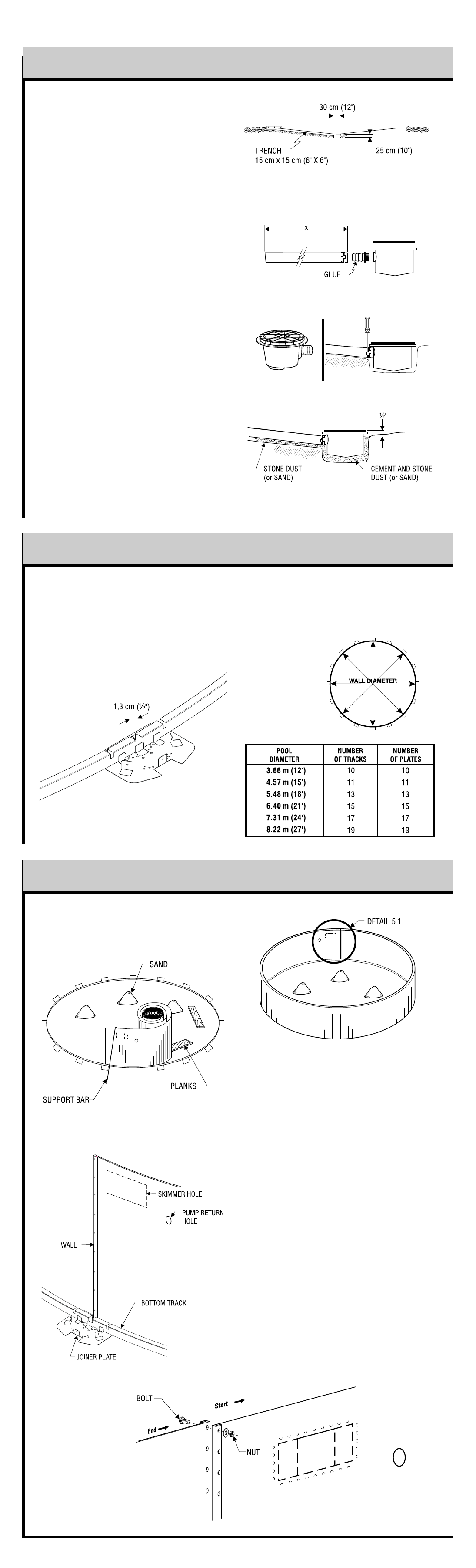
Insert the wall tracks on each side of the joiner plates,
making sure to leave a 1.3 cm (½") space etween the
ends of oth tracks, in the center of the joiner plate (See
Illustration 4.1).
Make a complete circle, using half of the wall tracks and
joiner plates found in the pool kit (See Chart and
Illustration 4.2).
BOTTOM WALL TRACKS ASSEMBLY
4
Before uncoiling the wall, make sure the pre-punched
holes for the skimmer and pump return are at the top and
facing the planned location of your filter.
Begin inserting the wall into the ottom wall tracks in the
middle of a joiner plate. At first, the wall should e kept in
place with one or two support ars (or extra persons).
One person should uncoil the wall on a eam or a plank
while a second person inserts it in the ottom wall tracks.
Do not uncoil more than 3 m (10') of wall efore you
install a support ar to reinforce the structure.
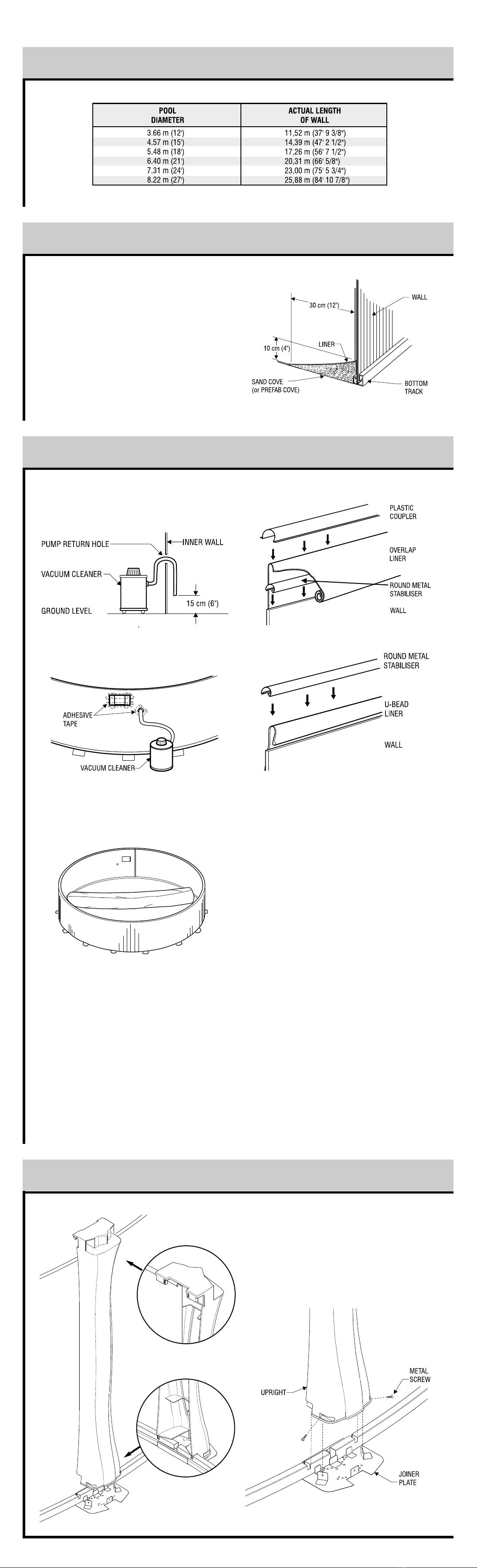
Once the wall is completely uncoiled, you may find that it
is too long or that oth ends do not meet y a few cen-
timetres. If such is the case, you must gently push the
wall in or out. If this does not work, roll up the wall again,
realign the grooves and uncoil the wall once more. If the
spread is too wide, measure the wall and check it against
the following chart.
When you prepare to join the ends of the wall, make sure
the end that is reinforced y the fold is inside the circle,
facing the liner and that the other end faces outward (See
Illustration 5.1). When the wall joint is screwed, install the
round sta iliser on top of it.
IMPORTANT: Due to the enormous pressure exerted y
the water on the steel wall, it is a solutely essential that all
bolts are screwed in tightly and that no hole is left open.
All olt heads must e inside with washer and nut outside.
Cover all olt heads with heavy fa ric tape.
WALL INSTALLATION
5
Illustration 4.1 Illustration 4.2
Inside
Outside
Chart
Illustration 5.1 Inside
Outside
Dig a hole 30 cm (12") wide y approximately 25 cm
(10") deep in the center of the circumference.
From the center hole to the projected location of the pool
motor, dig a 15 cm (6") wide trench. Place the removed
soil aside to e used later to cover the hose.
Bottom Drain Assembly
Place teflon around the threaded plug. Screw in drain
holes using large pliers. Glue the connector in the appro-
priate opening.
Take one of the two ru er rings and adjust it to the top of
the drain, aligning the holes carefully. Secure with strips
of adhesive tape to prevent sand from penetrating inside
the holes once the drain has een installed.
Secure one end of the long lack or white hose inside the
drain spout. First apply glue on the drain spout and inside
the drain end, then secure with one or two collars.
Cut the hose so that it ends with the stone dust (or sand).
Measure the pool radius from the center of the drain, then
add 15 cm (6").
Place the assem led ottom drain in the hole so that it is
approximately 1.3cm (1/2") higher than the surface soil.
Bury the hose, levelling the drain as much as possi le.
Compact the soil, using your feet and a tampering tool as
well.
Mix three (3) shovels of stone or sand dust with one half
shovel of pure cement, adding a small quantity of water,
then pour the cement around the drain until it reaches 1.3
cm (1/2") from the top.
BOTTOM DRAIN ASSEMBLY (if applicable)
3

Attach the uprights to the bottom joiner plates with two
metal screws, witch you will find them in the hardware
bag.
Uprights must be installed outside the flanged part of the
joiner plate and in the two notch of the wall track.
Before pulling the liner up against the wall, insert a va-
cuum cleaner hose down into the pump return hole to
approximately 5 cm (6") from the ground.
Maintain the hose in place with adhesive tape. Don't for-
get to block the skimmer hole with adhesive tape to pre-
vent air from leaking in.
Place the unfolded liner in the center of the pool area at
right angles with the skimmer hole. Make sure you wear
light, flat-soled shoes to walk on the sand as the slightest
heel mark could be visible once the pool is filled.
Carefully unfold the liner, bringing the bottom-sidewall
seam close to the wall base. Make sure that the side with
the protruding seams faces downward or that the pat-
terned side faces upward.
Lift up a section of the liner over the top of the wall lean-
ing a 0 cm to 5 cm (4" to 6") fringe outside the wall.
Secure the liner with a plastic coupler.
At this point, the liner may be too tight, making it difficult
to drape the overlap or, on the contrary, too loose. In such
cases, you will have to redistribute the tension in the liner
by removing some of the couplers and readjusting the
liner.
Installation detail of the liner with the sqare steel track.
Hang the liner on the top of the wall and install the round
stabiliser to secure.
Start the vacuum cleaner to allow the liner to adhere to the
wall and check for excess tension at the bottom or for
wrinkles. Adjust the liner by removing couplers if needed,
to lift or lower it in order to ensure a perfect fit.
Fill the pool up to the base of the wall before stopping and
removing the vacuum cleaner.
PUMP RETURN FITTING
After you remove the vacuum cleaner, you may install the
return fitting. Place the return fitting ring against the liner
and adjust it so that it is perfectly aligned with the hole in
the wall. When the ring is properly positioned and
secured, cut the liner in the middle of the ring.
Insert the return fitting from the inside, placing the first
gasket between the return fitting and the liner and the sec-
ond between the wall and the liner. Then tighten the out-
side ring with large pliers, taking care not to crease the
liner.
BOTTOM DRAIN (optional)
Find the holes through the middle of the liner and screw
the ring and gasket in against the liner before cutting the
liner in the middle of the ring, then screw on the drain
cover.
VINYL LINER INSTALLATION
7
You can now spread approximately 0 cm (4") of com-
pacting sand all around the inside base of the wall in order
to protect the liner from the cutting edges of the bottom
wall tracks and the stone dust (if applicable). Or install a
prefabricated cove, if available.
SAND BASE FINISHING
Level finishing sand one last time. Make sure that any
sharp stones, debris or roots have been removed from the
surface. For better protection, spray sand with water and
pack it once more until the base is nicely even.
SAND BASE FINISHING
6
WALL INSTALLATION (continued)
5
UPRIGHT INSTALLATION
8
Chart

Note: See 'Safety Information" Manual, Page 1.
As described in the manual, all components of the filtra-
tion system should be placed to prevent a child to climb
on top and get access to the pool.
Using a little bit of stone dust (or sand), place at level a
patio stone 61cm x 6 cm (24" x 30") before installing the
motor and filter.
Position the motor on the stone and insert the two nozzles
to connect the hoses.
Then, install the filter tank. Adjust the lateral assembly
properly in its channel. It is sometimes necessary to
install the laterals.
Patch the center hole of the lateral assembly using the
plug to allow filtering sand to flow into the tank.
Remove the plug. Install the joint in the cavity and secure
the filter head by placing the back wash position on oppo-
site side of the pool.
Install necessary nozzles, then connect hoses using col-
lars.
1. The first hose runs from the top of the pump to the side
of the filter head;
2. The second one goes from the pump to the skimmer
(or to the bottom drain valve);
3. The third goes from the front of the filter head to the
water return or from the front of the chlorinator to the
water return.
A back wash hose may be placed behind the filter head.
If there is a chlorinator and/or heat pump, it must be
assembled at the filter exit.
FILTRATION SYSTEM ASSEMBLY
13
SEAT CAP INSTALLATION
11
Position the safety procedures panel on the outside of the
pool. This panel must be at the most visible place from the
yard on your pool.
Place the three (3) safety stickers inside the pool in a way
that it’s seen from any entry point of the swimmer (See
positionning drawing).
SECURITY SIGNS INSTALLATION
12
TOP SEAT INSTALLATION
9
TOP SEAT INSTALLATION
10
For Model Trevi 209, put the seat cap on the inside sec-
tion of the seat and interlock with the upright, and secure
with one (1) metal screw. Place the screw cap on the top.
Place the top seat on the upper side of the upright, and
secure with two (2) metal screw. The screw in the interi-
or pool side must be protected on the bit with the screw
guard.
For Model Trevi 209, position the joiner plate on the upper
side of the upright, and secure with two (2) metal screw.

PARTS LIST
15
Insert threaded nozzles, if applicable, in order to be able to
screw the valve in the skimmer.
Connect the drain hose to the bottom nozzle. Connect the
motor hose to the side nozzle.
The threads on all threaded nozzles must be covered with
teflon tape prior to installing in order to prevent water
leaks. Teflon is applied to the threads as follows: little or
none on the first few threads (to facilitate introduction)
and several la ers towards the end threads (for better
watertightness).
DRAIN VALVE ASSEMBLY (if applicable)
14
Table of contents