ULNA CPE988 User manual
WIRELESS BRIDGE
Tips:
Thank you for ordering and using ULNA CPE988 Wireless Bridge, please read
the manual carefully before use. If there are any problems during the use,
please contact us in time.
The installation of this device requires some network knowledge. If you can't
install it, please let us know or contact a professional.
Model: CPE988
USER MANUAL

Contents
1. Overview
(1.1) Introduce
(1.2) Highlights
(1.3) Specifications
2. Package Included
3. Interface Details
(3.1) Button Operation
4. LED Indicator Details
5. Quick Start
(5.1) POE Power Supply
(5.2) Point to Point Pairing Step
(5.3) Point to Multipoint Pairing Step
6. Installation
(6.1) Pole Mount
(6.2) Wall-mounted
(6.3) Connect to the Device
7. WiFi Function
8. Application Cases
(8.1) Case 1: PTP extended network WiFi range
(8.2) Case 2: PTP extended of surveillance cameras range
(8.3) Case 3: PTMP extended surveillance cameras range
(8.4) Case 4: PTP extended surveillance cameras range
9. Advanced Settings
10. Troubleshooting
11. Technical Support and Service
1
1
1
2
3
3
4
4
6
6
6
7
7
7
8
8
9
10
10
10
10
11
11
15
17

1. Overview
1.1. Introduce
01
ULNA CPE988 is a long-distance 5.8G wireless transmission device. It uses
wireless communication technology to transmit network data using air as a
medium to perform long-distance point-to-point or point-to-multipoint
interconnection. The working data link layer realizes the interconnection of
local area networks. The transmission distance can reach up to 5km.
CPE988 Video Bridge Transmission usually consists of two devices in AP and
Client mode respectively. On the Client-side (Receiving side) CPE connects
with IP Camera, at the AP side (Transmitting side) CPE connects with a video
recorder. The AP can be receiving wireless data transmitted from multiple
Clients, and it is easy and convenient for centralized management of the
remote equipment.
CPE is widely used in highways, reservoir river monitoring, elevator monitoring
systems, site crane monitoring systems, port terminal monitoring systems,
marine aquaculture monitoring systems, and so on.
Point to point extend network WiFi range, extend the network in the house to
your barn, garage, church, warehouse, and even neighbor's house through
wireless bridge signal transmission. No need to install a new modem and pay
for it every month, saving you money.
1.2. Highlights
1. Transmission using 5.8Ghz wireless technology
2. 1000Mbps RJ45 LAN port, support Gigabit
3. Built-in 16dbi high gain WiFi antenna
4. IEEE802.11ac IEEE802.11n,IEEE802.11a ,IEEE802.3u
5. Transmission distance up to 5km(Barrier-Free)
6. Master bridge supports WiFi hotspot access
7. Dialing to set the transmitter and receiver, is easy to use
8. Support point-to-point, point-to-multipoint mode
9. Dynamic MIMO power saving mode (DMPS) and APSD
10. Support 24V POE power supply, easy to install and deploy
11. Support WEB GUI access management device.

1.3. Specifications
ULNABrand
CPE988Model
MT7620A+7612ECPU
8MByteFlash
DDR2 128MByteDRAM
10/100/1000Mbps LAN x 1 & 10/100Mbps LAN x 1
Interface
11a: 54M,48M,36M,24M,18M,12M,9M,6Mbps
11n: 7.2M,14.4M,21.7M,28.9M,43.3M,57.8M,65M,
72.2M,14.4M,28.9M,43.3M,57.8M,86.7M,115.6M,
130M,144.4Mbps 433Mbps
Data rate
Direct Sequence Spread Spectrum(DSSS)Transfer method
OFDM/BPSK/QPSK/CCK/DQPSK/DBPSKModulation
IEEE802.11ac IEEE802.11n,IEEE802.11a ,IEEE802.3uProtocol standard
4900~6100MHzFrequency Range
≤3W, POE 24V~1A/48V~0.5APower
16dBi,Horizontal 60°/Vertical 30°Antenna
SupportWEP GUI
SupportTelnet
SupportSerial
WEP 64/128bits,WPA,WPA2,802.1xSafety
-30~65℃Temperature
11.8*11.5*2.7 inch & 2.2 LBBox Size & Weight
CSMA/CA,TCP/IP,IPX/SPX,NetBEUI,DHCP,NDIS3,
NDIS4,NDIS5
Agreement
2. Package Included
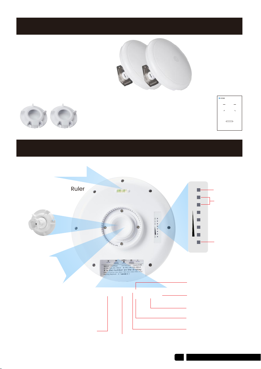
3. Interface Details
03
2 x CPE988 Gigabit Bridge
2 x Gigabit POE Adapter (24V)
2 x Cat 5e Network Cable
2 x Metal Hoop
2 x Mounting Screw Set
1 x User Manual
Horizontal Ruler
WLAN
Signal Light
Universal Ball Head
Fixed Bracket
DC(Unavailable)
Reset Button
B-A Button
1000Mbps LAN/POE
100Mbps LAN/POE
Digital Tube
A-B Light
LAN2 WLAN
LAN1
PWR
LAN1/LAN2
Power
Indicator
WIRELESS BRIDGE
Tips:
Thank you for ordering and using ULNA CPE988 Wireless Bridge, please read
the manual carefully before use. If there are any problems during the use,
please contact us in time.
The installation of this device requires some network knowledge. If you can't
install it, please let us know or contact a professional.
Model: CPE988
USER MANUAL

4. LED Indicator Details
3.1. Button Operation
Reset Button:
Press and hold for 10S to reset the wireless bridge; in setup mode, short press
once to toggle a different character to pairing.
A-B Button:
Pushing the button to "A" indicates that the bridge acts as the master bridge
(transmitter), and pushing the button to "B" indicates that the bridge acts as
the slave bridge (receiver).
1000Mbps
LAN Port
Gigabit PoE
Adapter
PoE Port
LED
WLAN
Signal Light
LAN2 WLAN
LAN1
PWR
LAN1/LAN2
Power
Indicator
0 1 2 F
Receiver B mode Transmitter A mode

05
DescriptionLED Light
Power indicator, the LED is on after the power is
connected
PWR
Digital display LED display "H" indicates manual
configuration status
Digital Tube
Digital display LED display "L" and flashing
indicates settings status
Digital Tube
Digital display LED flashing indicates edit the
config or connecting
Digital Tube
Display that a fixed number is solid, it means
that the two bridges are paired successfully
and are working.
Digital Tube
A, B status lights, lighting is B mode, no lighting is
A mode.
Point Light
Click once to switch different characters, looping
from0, 1, ..., F. Characters represent channels.
RST Button
Long-press 10s on the "RST" button and the
bridge will auto-reset.
RST Button
24V power supply and data transmission
PoE Port of
Adapter
Only data transmission and DC in, can’t power
other devices
PoE Port of
Bridge/LAN
The bridge switches the master and slave
bridges through the A-B button, A represents the
master bridge, and B represents the slave bridge.
A-B Button
After the bridge is connected successfully,
the 5 grid green WLAN lights will be on;
otherwise, only 1 grid green WLAN light will be on.
WLAN Signal
Lights
The data connection is successful, the LED light
is on, otherwise, it is not bright.
LAN1/LAN2
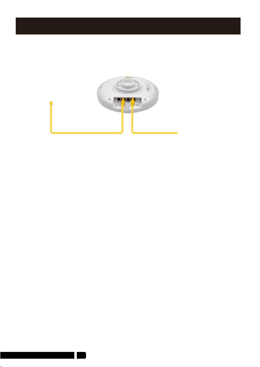
5. Quick Start
5.1 PoE Power Supply
The CPE988 wireless bridge adopts a PoE power supply, which is easy to install
and manage while saving costs.
5.2 Point to Point Pairing Step:
1. Switch one unit to A(Master Bridge) and one unit to B(Slave Bridge)
2. Connect the POE to each unit using the Ethernet cable and plug the POE in;
3. Wait for them to power up, about 2 min;
4. Use the tiny reset button to click through until you get a channel with a letter.
1,2,3,..., A,B,C,...,F, here used C;
5. Then on the other unit do the same. Both units need to be on the same
channel;
6. Wait for 2-5 minutes to complete the pairing. When the number of the digital
tube is solid and the signal light on the side turns on, it means the pairing is
successful;
7. Finally connect other devices(Router, PC, Switch) and install them to the
target location.
(TIPS: Steps 1, 4 and 5 are already pre-set at factory)
1.1. According to the requirements, prepare a long enough network cable
(Recommended within 20 meters, must Cat 5e or up)to connect the
wireless bridge and the PoE power supply. The PoE port of the PoE power
supply is connected to the WAN port of the wireless bridge.
1.2. The LAN port of the PoE power supply is connected to the PC, router, and
switch.
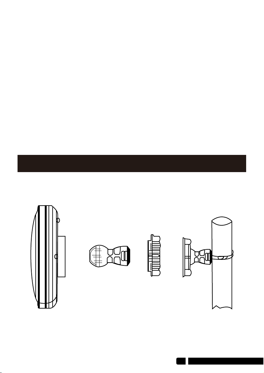
6. Installation
07
6.1 Pole mount
5.3 Point to Multipoint Pairing Step:
e.g. 1 master bridge with 3 slave bridges
1. Switch one unit to A(Master Bridge) and 3 units to B(Slave Bridge);
2. Connect the POE to each unit using the Ethernet cable and plug the POE in;
3. Wait for them to power up, about 2 min;
4. Use the tiny reset button to click through until you get a channel with a letter.
1,2,3,..., A,B,C,...,F, here used C;
5. Then on the other 3 unit do the same. 4 units need to be on the same
channel;
6. Wait for 2-5 minutes to complete the pairing. When the number of the digital
tube is solid and the signal light on the side turns on, it means their pairing is
successful;
7. Finally connect other devices(Router, PC, Switch) and install them to the
target location.

Table of contents
Other ULNA Network Hardware manuals


Popular Network Hardware manuals by other brands

Matrix Switch Corporation
Matrix Switch Corporation MSC-HD161DEL product manual

B&B Electronics
B&B Electronics ZXT9-IO-222R2 product manual

Yudor
Yudor YDS-16 user manual

D-Link
D-Link ShareCenter DNS-320L datasheet

Samsung
Samsung ES1642dc Hardware user manual

Honeywell Home
Honeywell Home LTEM-PV Installation and setup guide


