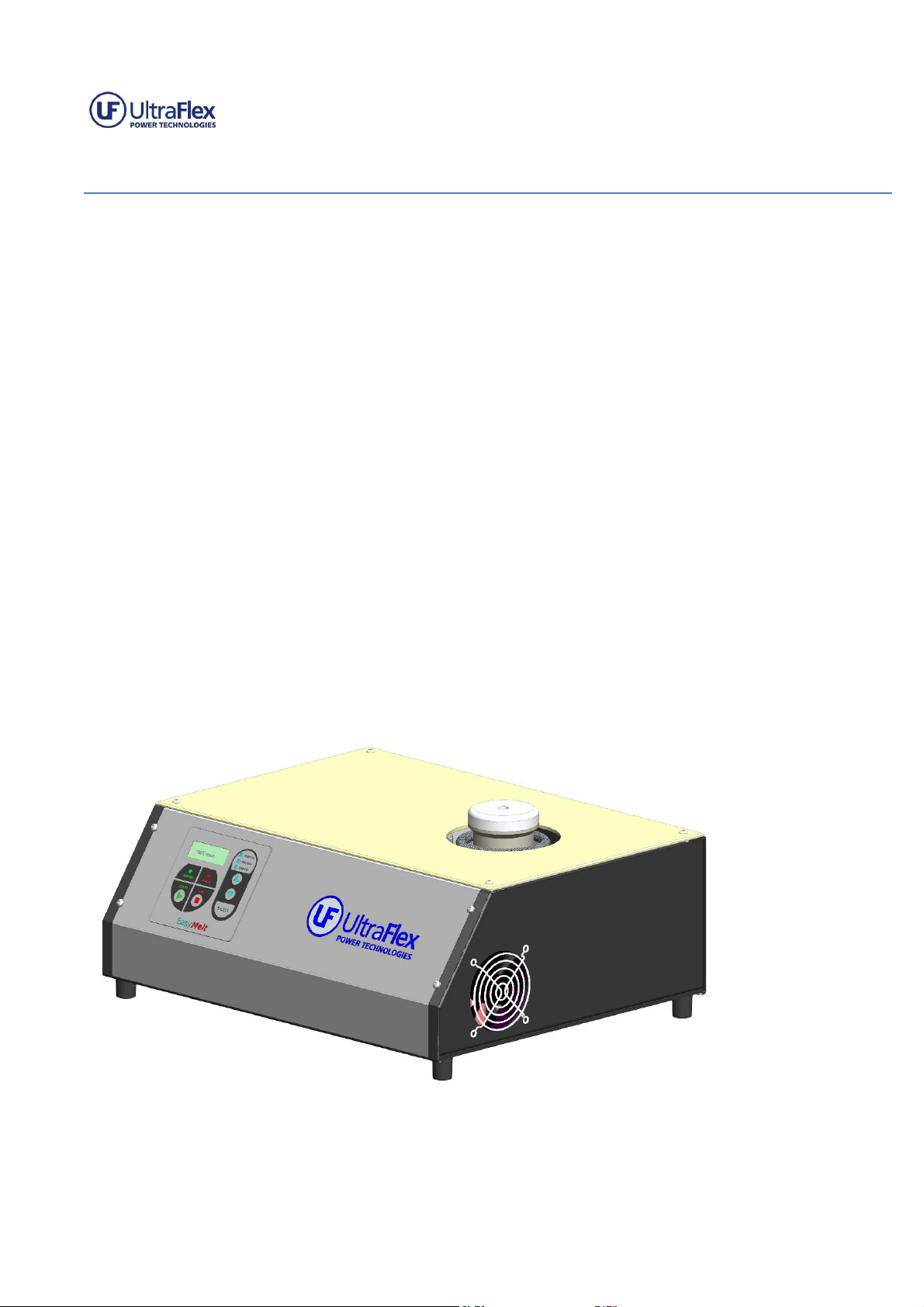
UPT Series Easy Melt
Operation Manual
Version 1.2 2
www.ultraflexpower.com
TABLE OF CONTENTS:
1 GETTING STARTE GUI E ................................................................................................................................... 3
1.1 SAFETY INSTRUCTION .............................................................................................................................. 3
1.1.1 IMPORTANT NOTES ............................................................................................................................ 3
1.1.2 SAFETY PRECAUTIONS ........................................................................................................................ 4
1.1.2.1 ELECTRICAL SHOCK HAZARDS ........................................................................................................ 4
1.1.2.2 GROUNDING ................................................................................................................................. 4
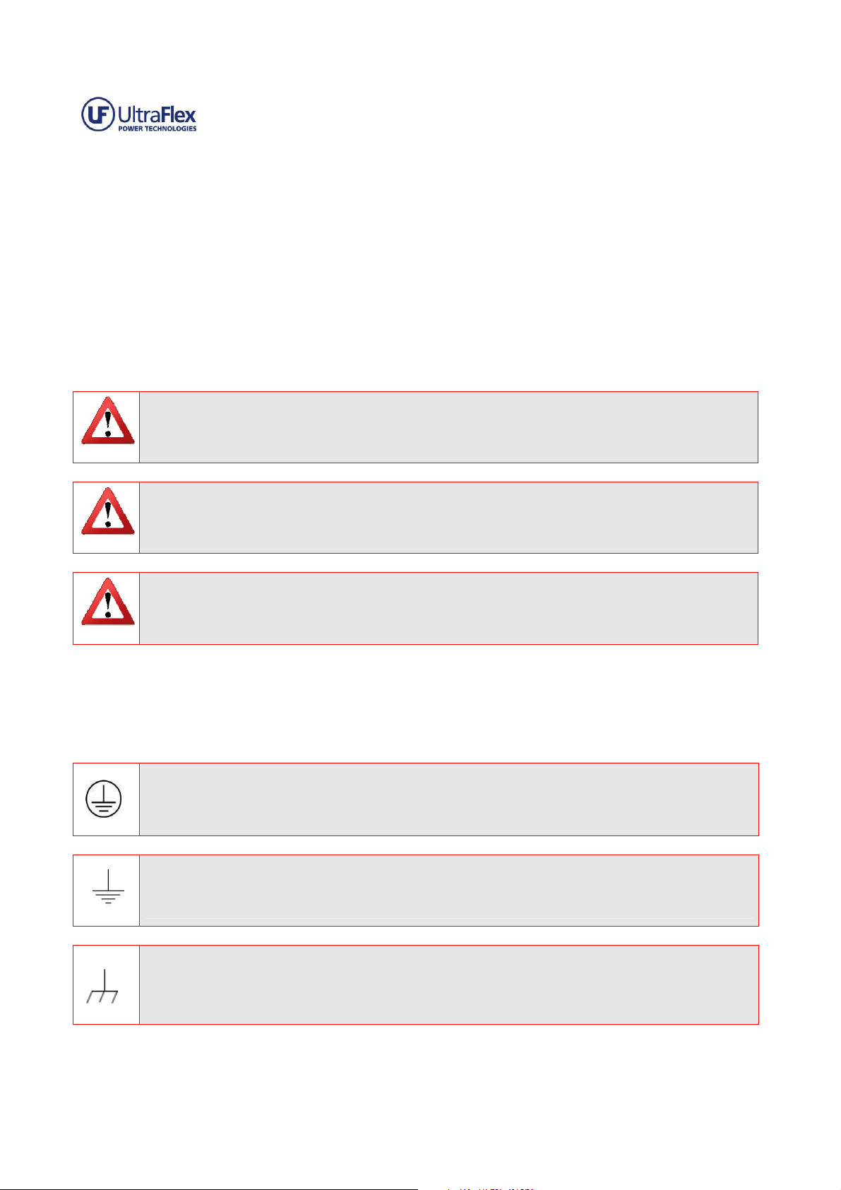
1.1.2.3 SAFETY AND PRECAUTION SYMBOLS USED IN THIS MANUAL ......................................................... 5
1.1.2.4 MAGNETIC FIELD ........................................................................................................................... 5
1.2 INSTALLATION AN START UP ................................................................................................................. 5
1.2.1 INSTALLATION PROCE URE ................................................................................................................ 5
1.2.2 UNPACKING AN INSPECTION ............................................................................................................ 6
1.2.3 SELECTING THE EVICE SITE ............................................................................................................... 6
1.2.4 COOLING REQUIREMENTS .................................................................................................................. 6
1.2.5 AC INPUT CONNECTION ..................................................................................................................... 6
1.2.6 START-UP ........................................................................................................................................... 7
1.2.7 USING THE MACHINE ......................................................................................................................... 7
1.3 MAINTENANCE........................................................................................................................................ 8
1.3.1 SCHE ULING ........................................................................................................................................... 8
1.3.2 PERSONNEL ........................................................................................................................................ 8
1.3.3 INSPECTION AN MAINTENANCE PROCE URE ................................................................................... 8
2 PRO UCT SPECIFICATIONS AN FEATURES ......................................................................................................... 9
2.1 PRO UCT SPECIFICATIONS ...................................................................................................................... 9
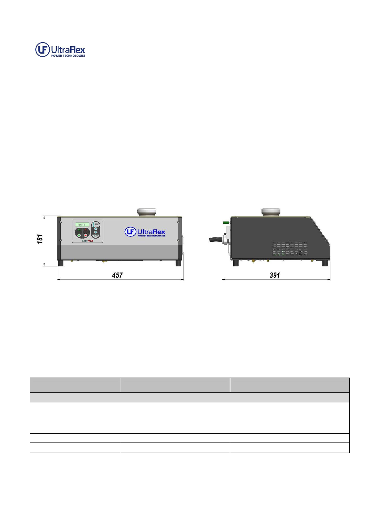
2.1.1 OVERVIEW ......................................................................................................................................... 9
2.1.2 EVICE SPECIFICATIONS TABLE ........................................................................................................... 9
2.1.3 CONNECTION IAGRAM ................................................................................................................... 10
2.2 CONTROLS AN OPERATION ................................................................................................................. 11
2.2.1 CONTROL PANEL OVERVIEW ............................................................................................................ 11
2.2.2 CONTROLS AN IN ICATORS ........................................................................................................... 11
2.2.3 REGULATION MO ES AN SYSTEM STATUSES .................................................................................. 12
2.2.4 MENUS AN NAVIGATION ............................................................................................................... 13
2.2.4.1 Main M nu Navigation ................................................................................................................ 13
2.2.4.2 H at ON M nu Navigation .......................................................................................................... 13
2.2.4.3 SYSTEM MENU Navigation .......................................................................................................... 15
2.2.4.4 EXTENDED MENU Navigation ...................................................................................................... 16
2.2.5 CONTROL MO ES............................................................................................................................. 19
3 TUNING AN TROUBLESHOOTING .................................................................................................................... 19
3.1 LOA TUNING GUI E ............................................................................................................................ 19
3.2 SERVICE AN TROUBLESHOOTING ........................................................................................................ 19
3.3.1 ERROR MESSAGES ............................................................................................................................ 19
3.3.2 GENERAL .......................................................................................................................................... 21
3.3.3 SERVICE CONTACT INFORMATION .................................................................................................... 21
Appendix A: RECOMMEN E SPARE PARTS KIT ................................................................................................... 22
Appendix B: ACCESSORIES ................................................................................................................................... 22