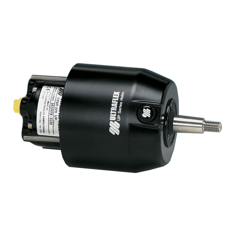
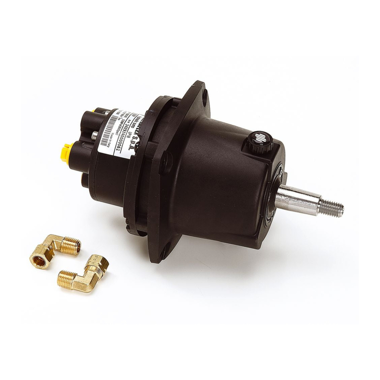
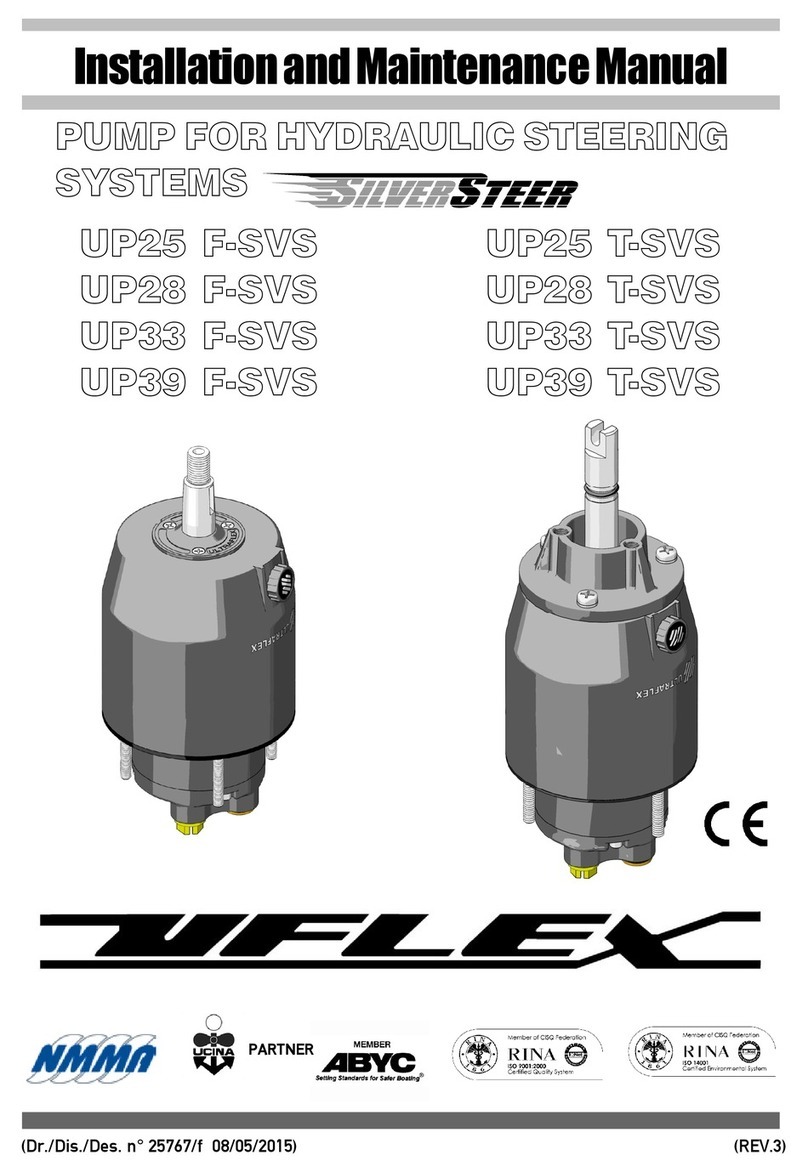
Ultraflex UP25 F Manual

PUMPFORHYDRAULIC
STEERINGSYSTEMS
InstallationandMaintenanceManual
(Dr.No. 26334/f08/05/2015)
ITALIANO
SOCIO
(REV 4)
UP25F
UP28F
UP33F
UP39F
UP45F
UP25NVF
UP33NVF
UP28R
UP33R
UP39R
UP39-IR
UP45R
UP45-IR
UP25T
UP28T
UP33T
UP39T
UP45T

DearCustomer,
Wewould liketothankyouforchoosingan ULTRAFLEX SpAproduct.
ULTRAFLEX SpAhas beenaleaderinsteeringsystemsforpleasureandprofessionalboatsformany
years.
All ULTRAFLEX SpAproductsaredesignedandmanufacturedtoensurethebestperformance.
To ensureyoursafetyandtomaintainahighqualitylevel, ULTRAFLEX SpAproductsareguaranteedonly
iftheyareusedwithoriginalspareparts(see attacheddocument"ApplicationSpareParts").
ULTRAFLEX SpAandQualityManagementSystemis certifiedCISQ-IQNetbytheItalianShippingRegistry
(RINA),inconformitywiththeUNIENISO9001:2008 rule. ULTRAFLEX SpAcertificationNo. 6669/02/S(former
420/96).
Thequalitymanagementsysteminvolvesallthecompanyresourcesandprocesses startingfromthe
design,inorderto:
- ensureproductqualitytothecustomer;
-maintainandimprovethequalitystandardsconstantly;
-pursueacontinuousprocess improvementtomeetthemarketneedsandtoincrease thecustomer
satisfaction;
-constantlytesttheproductstoverifytheirconformitywiththe2013/53/EU.
"Establishedin1989 UFLEX USAis aleaderinsteeringandcontrolsystemsforthemarineindustry.
Withfull manufacturingcapabilities inSarasota, Florida, UFLEX USAcansupportall sectorsofthemarine
industryregardlessofvolumeand/orproductrequirements.And,as anaffliateofthe ULTRAFLEX Group,
UFLEX USAhas tremendousresources todrawuponfornewproductdevelopmentinhydraulics, electronics
andmanyothertechnologies.
Innovativeproductdesignandunparalleleddedicationtoqualitycustomerserviceandproductsconti-
nuetobecornerstoneof UFLEX USA'sgrowth.Todayourproductscanbefoundasoriginallyinstalled
equipmentonmanyofthemostwidelyknownandrespectedboatbrandsintheworld.
AftermarketpartscanbesourcedfromtrainedandexperienceddistributornetworktroughoutNorth
andSouthAmerica.
Ourdedicationtoprovidingthehighestqualityproductsandserviceis onlymatchedbyourcommitment
todevelopingnewproductsemployingthelastestmaterialsandtechnologytoenhanceourcustomer's
boatingexperience. Fromsteeringwheelstosophisticatedelectroniccontrols, UFLEX USAhas everything
youneedtomakesurethatyourboatlooksandperformit's bestformany,manyyears."
UFLEXUSA
Sarasota,FL34243 -6442 ParklandDrive

PUMP FORHYDRAULICSYSTEMS -page3 of35
Installationandmaintenancemanual
SECTION1-PRODUCTDESCRIPTION
1.1 HYDRAULICSTEERINGSYSTEMOPERATION.................................................................................................8
1.2 WARNINGSFOR THECORRECTPRODUCTUSE..............................................................................................8
1.3 SYSTEMCONFIGURATIONS...............................................................................................................................9
1.4 PUMPDESCRIPTION............................................................................................................................................9
1.5 PUMPTECHNICALFEATURES...........................................................................................................................10
TABLEOFCONTENTS
SECTION2-TRANSPORT
2.1 GENERALWARNINGS.........................................................................................................................................13
2.2 PACKAGINGCONTENTS......................................................................................................................................13
SECTION5-MAINTENANCE
5.1 ORDINARY MAINTENANCE.................................................................................................................................32
5.2 STEERINGWHEEL DISASSEMBLY....................................................................................................................32
5.3 TROUBLESHOOTING............................................................................................................................................32
SECTION3-INSTALLATION
3.1 TOOLSNECESSARYFOR THEINSTALLATIONOFPUMPSUP25F-UP28F-UP33F-UP39F-UP45F
UP25NVF-UP33NVF.....................................................................................................................................16
3,2 PUMPUP25 F-UP28 F-UP33 F-UP39 F-UP45 F-UP25NVF-UP33NVFINSTALLATION................16
3.3 TOOLSNECESSARYFORTHEINSTALLATIONOFPUMPSUP28 R-UP33 R-UP39 R-UP45 R..............18
3.4 PUMPUP28 R-UP33 R-UP39 R-UP45 RINSTALLATION..........................................................................18
3.5 TOOLSNECESSARYFORTHEINSTALLATIONOFPUMPSUP39-IR-UP45-IR.........................................20
3.6 PUMPSUP39-IR-UP45-IRINSTALLATION..................................................................................................20
3.7 TOOLSNECESSARY FORTHEINSTALLATIONOFUP25T-UP28 T-UP33 T-UP39 T-UP45 TPUMPS....22
3.8 PUMPUP25 T-UP28 T-UP33 T-UP39 T-UP45 TINSTALLATION...........................................................22
3.9 TYPESOFINSTALLATION..................................................................................................................................25
3.10 HOSECONNECTIONTO THESYSTEM..............................................................................................................26
3.10.1HOSECONNECTIONTO THESYSTEMFOR MODELSUP25 F-R-T, UP28 F-R-T, UP33 F-R-T, UP39 F-R-T,
UP45 F-R-T............................................................................................................................................................26
3.10.2HOWTO CHOOSETHERIGIDPIPESFOR MODELSUP39-IRANDUP45-IR..............................................26
3.10.3HOSECONNECTIONTOTHESYSTEMFOR MODELSUP39-IRANDUP45-IR................................................28
3.11 FILLINGANDPURGING.......................................................................................................................................29
3.11.1POSITIONINGOFTHEOILBOTTLE...................................................................................................................30
3.11.2PURGING PROCEDURE........................................................................................................................................30
3.12 GENERALRECOMMENDATION...........................................................................................................................30
SECTION6-DISMANTLING
6.1 DISMANTLING......................................................................................................................................................34
!
DOCUMENTREVISIONS..................................................................................................................................................4
MANUALUSEANDSYMBOLSUSED.............................................................................................................................5
INFORMATIVE LETTER.....................................................................................................................................................6
WARRANTY........................................................................................................................................................................6
SECTION4-SAFETYWARNINGS
4.1 SAFETY WARNINGSDURINGUSEANDINSTALLATION...............................................................................31
4,2 CLOTHING..............................................................................................................................................................31

page4 of35-PUMP FORHYDRAULICSYSTEMS
Installationandmaintenancemanual
DOCUMENTREVISIONS
Rev. Date Revisiondescription
0
1
2
3
4
10/02/2012
20/11/2012
30/07/2013
28/02/2014
16/07/2014
Firstedition
Models45 F-R-IR-Thavebeenadded andswivelingfittingchange
ModelUP39-IRhas beenadded
Corrections ofpicture references onpages 8 and9
Modificationofchapters"Packagingcontents"and"Positioningoftheoil
bottle"

PUMP FORHYDRAULICSYSTEMS -page5 of35
Installationandmaintenancemanual
Inthis manualthefollowingsymbolsareusedtoensuretheusersafetyandtoguarantee thecorrect
operationoftheproduct:
MANUALUSEANDSYMBOLSUSED
THEINSTALLATIONANDMAINTENANCE MANUALis thedocumentaccompanyingtheproductfromitssale
toitsreplacementanddischarge.Themanualis animportantpartoftheproductitself.
It is necessarytoreadcarefullythemanual,beforeANYACTIVITY involvingtheproduct,handlingand
unloadingincluded.
STERN
BOW
STARBOARD PORT Thepictureasideexplainsthemeaningofsome
nauticalwordscontainedinthismanual.
LEGEND
m.p.h.=milesperhour
km/h=kilometresper
hour
10 m.p.h.=8,69 knots
10 m.p.h.=16,1km/h
10 knots =11,5m.p.h.
10 knots =18,5km/h
10 km/h=6,21 m.p.h.
10 km/h=5,4knots
DANGER ImmediatehazardswhichCAUSEseverepersonalinjuryordeath.
WARNING
CAUTION
Thesymbolasideindicates all theoperationswhichmustbecarriedout
byqualifiedorskilledstaff,inordertoavoidhazards.
Werecommendtrainingthestaff inchargeoftheproductinstallation
andcheckingtheirknowledge.
NOTICE Importantinformationforthecorrectinstallationandformaintenance,that
doesnotcauseanydamage.
Denotes thatahazard existswhichcanresult ininjuryordeathifproper
precautionsarenottaken.
Denotes areminderofsafetypracticesordirectsattentiontounsafe
practices whichcould result inpersonalinjuryordamagetothecraft or
componentsortotheenvironment.

page6 of35-PUMP FORHYDRAULICSYSTEMS
Installationandmaintenancemanual
WARRANTY
1. TwoYearLimited Warranty. UFLEX USA, Inc.warrantsthatallproductsmanufacturedby UFLEX USA,
Inc.or ULTRAFLEX S.p.A. andsold by UFLEX USAtotheretailpurchaser("Purchaser")thatfortwo(2)years
afterthedateofmanufacturetobefreefromdefectsduetomaterialorworkmanship,subjecttothe
exclusionsbelow.ImproperinstallationAVOIDSthis warranty.Installationshould onlybeattempetedby
atrainedandqualifiedtechnician.
2.Exclusions. Thislimitedwarrantydoesnotcoveranddoesnotextendtoanyofthefollowing:
(a) Failurecausedbynormalwearandtear,climaticconditions,misure,neglect,lackofproper
maintenance, accident,fireorothercasualtydamage, racing,overloading,negligence, modification,
beachingorgroundingofvessel,collision,impact,towing,actsofwarorhostilities;
(b) componentsnotmanufacturedby UFLEX USA, Inc., oritsaffiliates;
(c) costofremovalorreinstallationofanycomponent(includingcomponentsmanufacturedby UFLEX
USA,Inc.)ordisassemblyorreassemblyoftheunitcontainingthecomponent;
(d) componentsnotmanufacturedby UFLEX USA, Inc.or ULTRAFLEX S.p.A., whetherornotwarrantedby
theothermanufacturer;
(e) anyproductwhichhasnotbeenproperlyinstalled.
TECHNICALASSISTANCE SERVICE
INFORMATIVELETTER
North-South-CentralAmerica:
UFLEX USA
6442 ParklandDrive
Sarasota, FL34243
Ph.:+1.941.351.2628
Fax: +1.941.360.9171
Email:uflex@uflexusa.com
www.uflexusa.com
UFLEX S.r.l.
ViaMiliteIgnoto,8A
16012 Busalla(GE)-Italy
Ph.:+39.010.962.01
Fax: +39.010.962.0333
Email:ut@uflexgroup.it
www.uflexgroup.it
Thisinstallationandmaintenancemanualis anintegrantpartoftheproductandshould beeasilyavailabletostaff
inchargeofuseandmaintenance.
Theusermustknowthecontentofthis manual.
UFLEX declines allresponsibilityforpossiblemistakes inthis manualduetoprintingerrors.
Althoughthemainfeaturesofthetypeofproductdescribedare notsubjecttochange, UFLEX Companyreserves
theright tomodifyanyparts, details andaccessories itdeemsnecessarytoimprovetheproductorfor
manufacturingorcommercialrequirements,atanytimeandwithoutbeingobligedtoupdatethismanual
immediately.
ALLRIGHTSARERESERVED.Publishingrights,trademarks,partnumbersandphotographsof UFLEX products
containedinthis manualare UFLEX property.
Greatcarehas beentakenincollectingandcheckingthedocumentationcontainedinthis manualtomakeitas
completeandcomprehensibleas possible. Nothingcontainedinthismanualcanbeinterpretedas warrantyeither
expressedorimplied-including,notinarestrictedway,thesuitabilitywarrantyforanyspecialpurpose.Nothing
containedinthismanualcanbeinterpretedasamodificationorconfirmationofthetermsofanypurchasecontract.
Toensurethecorrectproductandcomponentoperation,theproductmustbeinstalledbyqualifiedstaff.
Incase ofpartdamageormalfunction,please contactthequalifiedstaff orourTechnicalAssistanceService.
WARNING

PUMP FORHYDRAULICSYSTEMS -page7 of35
Installationandmaintenancemanual
3. Limitations. THEREPAIROR REPLACEMENTOFDEFECTIVE PARTSSHALL BEPURCHASER'SSOLE AND
EXCLUSIVE REMEDY AND UFLEX USA, INC,'SSOLE ANDEXCLUSIVE LIABILITY UNDERTHISWARRANTY.
LABORFORREPLACEMENTISNOTINCLUDED. UFLEX USA, Inc.'s obligationunderthis warrantyis limited
totherepairorreplacement(at UFLEX USA, Inc.'s soleelection)ofanycovereditemfoundtobedefective,
whendeliveredbyPurchaserpursuanttowrittenauthorizationandinstructionsfrom UFLEX USA, Inc.,
shippingprepaidto UFLEX USA, Inc.'s plantorotherdesignatedrepairfacility.Repairedorreplaced
itemsarewarrantedasprovidedhereinfortheunexpiredportionoftheapplicablewarrantyperiod.
THISWARRANTY, ANDTHERIGHTSANDREMEDIESUNDERIT, ISEXCLUSIVE ANDISGIVENINPLACE OF
ALLOTHERWARRANTIES,WHETHEREXPRESSOR IMPLIED, INCLUDINGANYIMPLIEDWARRANTYOF
MERCHANTABILITYOR FITNESS FOR PARTICULARPURPOSE,WHETHERARISINGBY LAW,CUSTOM,
CONDUCTOR USAGEOFTRADE,PURCHASER'SREMEDIESSHALL BELIMITEDASSTATEDHEREINAND
UFLEX USA, INC.SHALL NOT BELIABLE FOR ANYINCIDENTAL,CONSEQUENTIALOR INDIRECTDAMAGES
OR LOSSESRESULTINGFROMDEFECTS.THERETAILSELLERISNOT ACO-WARRANTOR ANDISNOT
AUTHORIZEDBY UFLEX USA, INC.TO AMENDOR MODIFYTHISLIMITEDWARRANTY INANYMANNER.
4.TransferabilityofWarranty. Thislimitedwarrantymaynotbetransferredtosubsequentpurchasers.
5.Miscellaneous. UFLEX USA,Inc.isanaffiliateof ULTRAFLEX S.p.A. UFLEX,USA,Inc., reservestherightto
makechanges inthedesignandconstructionofitsproductsatanytime, withoutnoticeandwithoutany
obligationtoincorporatesuchchanges intoproductsofpriormanufacture. This limitedwarrantyapplies
tonewcomponentssold by UFLEX USA, Inc.. This limitedwarrantycontainstheentireagreementsbetween
UFLEX USA,Inc.andPurchaserandsuspersedesallprioragreements,discussions,negotiations,
commitmentsandrepresentations,whetheroralorwritten,betweenthemregarding UFLEX USA,Inc's
warranty.If anyprovisionofthis limitedwarranty,ortheapplicationofit,is determinedtobeinvalidof
unenforceableforanyreason,theremainderofthislimitedwarrantyandtheapplicationofitshall not
beaffected.
6.Ultron3000 andPowerC. TheUltron3000 and"PowerC-UserandInstallationManual"describes
activities,operations, technicalspecificationswhichmustbefollowedduringtheinstallationand/or
usageoftheproduct,inordertokeepavalidwarranty.Descriptionsanddrawingsinthatmanualare
suitabletoallowinstallationanduseoftheproducttoskilledpersons.Incase ofdoubtand/orforany
information,pleasecontactourTechnicalService.
AllcommunicationsandnoticesfromPurchaserregardingthislimitedwarrantyshouldbesentto: UFLEX
USA, INC., 6442 ParklandDrive, Sarasota, FL34243; (941)351-2628.
Returnpolicy
Anyproductthatis presumeddefectiveshould bereportedto UFLEX USAwithin48hoursofreceiptor
discoveryinthefield.Uponnotification UFLEX USAwill attempttotroubleshoottheproblemwithourcustomer
overthephone. If weareunabletoresolvetheproblem UFLEX willissueaReturnGoodsAuthorization
numberandwerequirethattheproductinquestionbereturnedto UFLEX withallitspartsinitsoriginal
packaging.Theproductshouldbereturnedfreightprepaidto:
UFLEXUSA
RGA Department-RGA #
6442 ParklandDrive
Sarasota,Florida34243
Uponreceipt UFLEX will examinetheproducttodeterminethecause ofthedefect.If theproductis determined
tohaveadefectinworkmanshipormaterial,itwill berepairedatourdiscretion.
Ourwarrantydoes notcoverlabor,towingorotherexpenses. Further,itdoes notcoverproductsthathave
beenimproperlyinstalled,damagedininstallation,misapplied,ormisused.
Ourproductsarenotintendedforuseinracingapplications.

page8 of35-PUMP FORHYDRAULICSYSTEMS
Installationandmaintenancemanual
1.2Warningsforthecorrectproductuse
1PRODUCTDESCRIPTION
1.1Hydraulicsteeringsystemoperation
UFLEX steeringsystemsmustnotbeinstalledonraceboats.
All UFLEX steeringsystems mustnotbe installedonboats equippedwithengines whose maximumhorsepower
ishigherthanthehorsepowerratingapprovedbyboatmanufacturer.
Donotmodifythesteeringcylinderinanywaytofitittoyourapplication,otherwise thecylinderwillno
longeroperateinsafetyanditwill endangertheboatandtheoccupants.
WARNING
WARNING
DANGER
l
engine
hydraulichoses
cylinder
l
l
l
pump
ThepumpsUP25NVFandUP33NVFcannotbeusedwithunbalancedcylindersandwithdoublesteering
system.
WARNING
All UFLEX hydraulicsteeringsystemsaredesignedinconformitywithUNI-EN-ISO10592andA.B.Y.C.P21
regulations. All UFLEX steeringsystemscanoperateattemperatures between-18°C(0°F)and+77°C(+170°F).
Allthecomponentsaremadeforthemarineenvironment,usingmaterialsandworkingprocesses which
offerlonglifeandsafetyunderthemostextremeconditions. Ahydraulicsteeringsystemconsistsofa
steeringpumplocatedonthedashboard,acylindertiedtotherudder
ortotheoutboard orsterndriveengineandtheconnectinghoses
(see picture).Undernormaloperatingconditions, aturnofthe
steeringwheelwillpumptheoil,whichflowsinthroughthehoses
tothecylinder,accordingtotheturndirection.Withtheconsequent
cylindermovementtheoilwillflowtothepumpthroughthehoses
andatthesametimemovestheengineorthehelmwhichare
connectedtothecylinder.Thepumpsequippedwithanonreturn
valve, whichpreventsoutgoingfluidfromreturningalongthesame
hose. allowtheoperationofthesteeringsystemswithtwoormore
steeringstations.Thepumpsseries"NV"arenotequippedwitha
nonreturnvalvesotheycannotbeusedwithtwoormoresteering
systems. Thecylindersaredouble-actingandtheycanbebalanced
orunbalanced.Inunbalancedcylindersthetwochambershave
differentvolumes andthereforetheyrequireadifferentnumberof
steeringwheelturnsandadifferentsteeringwheelrotationeffortwiththesamemovementinthetwo
directions. Theunbalancedcylinderscannotbeusedwiththepumpsseries"NV".Thebalancedcylinders
requirethesamenumberofturnsofthesteeringwheeltomovethehelmfromthecentretotheendof
strokeinthetwoopposeddirections.
Awell balancedsteeringsystemneedsacorrectchoiceofthepumpforthecylinder. UFLEX produces different
pumpmodels,whichhavedifferentcapacity(cm3ofoilmovedeachsteeringwheelturn)andforeachtypeof
installation. Whilechoosingthepumpitis importanttoconsiderthecylindervolume. The numberofstarboard
andportturnsis determinedbytheratiobetweenthecylindervolumeandthepumpcapacity.
Example:ifthepumphas acapacityof28cm3 [1,7cu.in.]andthecylinderhas avolumeof120 cm3 [7,3cu.in.],the
formulalookslikethis: 120/28=4,2.Accordingly,thesteeringwheelwill turnabout4times beforethecylinder
willcompletelyturnfromonesidetotheother.Incase ofinstallationswithdoublecylindersconnectedin
parallelthecylindervolumemustbeadded.Applicationswithless than4turnsarenotrecommended,as
theyneedahighereffort,also applicationswithmorethan8turnsarenotrecommended,as theresponse
oftheboattosteeris slowly.

PUMP FORHYDRAULICSYSTEMS -page9 of35
Installationandmaintenancemanual
1.3Systemconfigurations
ThepumpsUP25 -UP28 -UP33 -UP39 -UP45 canbeinstalledinasingleordoublesteeringsystemand
usedwithdifferenttypesofconfigurationsoffront,sideorinboard cylinders.
Thepumpsseries "NV"cannotbeinstalledinadoublesteeringsystemandtheycannotbeusedwith
unbalancedcylinders.
CAUTION
Alwaysconnectthehosescorrectlyasindicatedintheinstallationandmaintenancemanualsofthe
correspondinghydrauliccylinders.
1.4Pumpdescription
ThepumpsUP25 -UP28 -UP33 -UP39-UP45havebeendesignedandmanufacturedtobeusedasa
componentinthehydraulicsteeringsystems,asdescribedinthepreviousparagraph.
The pumpsUP25 F-UP28 F-UP33 F-UP39 F-UP45 F-UP25NVF-UP33NVFmustbe installedonthe front
partoftheboatdashboardorsemi-built-inthroughflangesX64orX57(suppliedseparately),thepumps
UP28 R-UP33 R-UP39 R-UP39-IR-UP45 R-UP45-IRmustbeassembledontherearpartoftheboat
dashboard,andthepumpsUP25 T-UP28 T-UP33 T-UP39 T-UP45 Tmustbeassembledbymeansoftilt
X52(suppliedseparately).
Thefollowingpictures showthemainpumpcomponents:
PumpUP25F- UP28 F-UP33 F-UP39F-UP45 F-UP25NVF-
UP33NVF
Tankplugwithbleed
Steeringwheelconnectionshaft
Connectionstothecylinder/s
Connectionstotheadditionalstations(thatcanbeusedwith
series"NV")
1
2
3
4
6
7
9
M6dowelsforfixingthepump tothedashboard
Pump UP28 R-UP33 R-UP39 R-UP39-IR-
UP45R-UP45-IR
M8dowelsforfixingthepump tothedashboard
PumpUP25T-UP28T-UP33 T-UP39T-UP45T
Connectionshaft totiltX52
510
8
UP25 F-UP28 F-UP33 F-UP39 F-UP45 F-UP25NVF-UP33NVF
2
3
6
4
1
4
5
5

page10 of35-PUMP FORHYDRAULICSYSTEMS
Installationandmaintenancemanual
1.5Pumptechnicalfeatures
Therelease pressureofthepressurereliefvalves does notcorrespondtothesystemnormalpressurebut
itrepresentsonlytheuselimits.
CAUTION
4
5
4
5
UP25 T-UP28 T-UP33 T-UP39 T-UP45 T
2
10 9
UP28 R-UP33 R-UP39 R-UP39-I R-UP45 R-UP45-I R
7
2
3
8
4
4
5
5
SPECIFICATIONS PUMPUP25 F PUMPUP25NVF PUMPUP28F PUMPUP33 F PUMPUP33NVF PUMPUP39 F PUMPUP45 F
Capacity 23,5cc/rev.-1,4
cu.in/rev.
23,5cc/rev.-1,4
cu.in/rev.
28 cc/rev. -1,7
cu.in/rev.
33 cc/rev. -2,0
cu.in/rev.
33 cc/rev. -2,0
cu.in/rev.
39 cc/rev. -2,4
cu.in/rev.
45 cc/rev.-2,7
cu.in/rev.
Pressurereliefvalve
releasepressure 70 bar(1000 psi) 70 bar(1000 psi) 70 bar(1000 psi) 70 bar(1000 psi) 70 bar(1000 psi) 70 bar(1000 psi) 70 bar(1000 psi)
No.ofpistons 5 5 5 7 7 7 7
Max.steering wheel
diameter 711 mm(28 in.) 711 mm(28 in.) 711 mm(28 in.) 711 mm(28 in.) 711 mm(28 in.) 711 mm(28 in.) 711 mm(28 in.)
Max.steering wheel
height 152 mm (6in.) 152mm (6in.) 152 mm (6in.) 152 mm (6in.) 152 mm (6in.) 152 mm (6in.) 152 mm (6in.)
Weight 5 kg(11 lbs) 5kg(11 lbs) 5kg(11 lbs) 5kg(11 lbs) 5kg(11 lbs) 5kg(11 lbs) 5kg(11 lbs)
Oil OIL15 OIL15 OIL15 OIL15 OIL15 OIL15 OIL15

PUMP FORHYDRAULICSYSTEMS -page11 of35
Installationandmaintenancemanual
Therelease pressureofthepressurereliefvalves does notcorrespondtothesystemnormalpressurebut
itrepresentsonlytheuselimits.
CAUTION
54 mm
[2,1in.]
108 mm
[4,25 in.] 90 mm
[3,54 in.]
UP25 F-UP28 F-UP33 F-UP39 F-UP45F-UP25NVF-UP33NVF
Æ67 mm [2,6in.]
Æ67 mm [2,6in.]
Æ19 mm [0,75 in.]
Æ115 mm [4,53 in.]
M12
Æ77 mm [3,03 in.]
198 mm [7,80 in.]
UP28 R-UP33 R-UP39 R-UP45 R
Æ114 mm [4,49 in.]
Æ
77 mm [3,03 in.]
Æ
115 mm [4,53 in.]
90 mm
[3,54 in.]
108 mm
[4,25 in.]
16 mm
[0,62 in.]
Æ
19 mm [0,75 in.]
M12
198 mm [7,80 in.]
min.dashboardthickness25,4mm [1in.]
max.dashboardthickness38,1mm[1,5in.]
SPECIFICATIONS
PUMPUP28 R
PUMPUP33 R
PUMPUP39 R
PUMPUP45 R
PUMPUP45-IR
Capacity 28 cc/rev.-1,7
cu.in/rev.
33 cc/rev.-2,0
cu.in/rev.
39 cc/rev.-2,4
cu.in/rev.
45cc/rev.-2,7
cu.in/rev.
45 cc/rev.-2,7
cu.in/rev.
Pressurereliefvalverelease
pressure 70bar (1000 psi) 70 bar (1000 psi) 70 bar(1000 psi) 70 bar (1000psi) 70 bar(1000 psi)
No.ofpistons 5 7 7 7 7
Max.steering wheel
diameter 711 mm(28 in.) 711 mm (28 in.) 711mm(28 in.) 711 mm(28 in.) 711 mm(28 in.)
Max.steering wheelheight 152 mm(6 in.) 152 mm(6in.) 152 mm(6in.) 152 mm (6 in.) 152 mm(6 in.)
Weight 5 kg (11 lbs) 5 kg (11 lbs) 5 kg(11 lbs) 5 kg (11lbs) 5 kg (11 lbs)
Oil OIL15 OIL15 OIL15 OIL15 OIL15

page12 of35-PUMP FORHYDRAULICSYSTEMS
Installationandmaintenancemanual
ThepumpsUP25 T-UP28 T-UP33T-UP39T-UP45Tcanonlybeusedwithtilt UFLEX X52 (supplied
separately).
CAUTION
Therelease pressureofthepressurereliefvalves does notcorrespondtothesystemnormalpressurebut
itrepresentsonlytheuselimits.
CAUTION
UP39-I R-UP45-I R
Æ114 mm [4,49 in.]
Æ
77 mm [3,03 in.]
Æ
115 mm [4,53 in.]
82 mm
[3,22 in.]
108 mm
[4,25 in.]
16 mm
[0,62 in.]
Æ
19 mm [0,75 in.]
M12
200 mm [7,87 in.]
min.dashboardthickness25,4mm [1in.]
max.dashboardthickness38,1mm[1,5in.]
UP25 T-UP28 T-UP33 T-UP39 T-UP45 T
174 mm [6,85 in.]
Æ127 mm[5in.]
255 mm [10,03 in.]
6°
Æ115 mm[4,5in.]
Æ77 mm[3,03in.]
SPECIFICATIONS
PUMPUP25 T
PUMPUP28 T
PUMPUP33 T
PUMPUP39 T
PUMPUP45T
Capacity 25cc/rev.-1,5
cu.in/rev.
28cc/rev. -1,7
cu.in/rev.
33cc/rev.-2,0
cu.in/rev.
39cc/rev.-2,4
cu.in/rev.
45cc/rev.-2,7
cu.in/rev.
Pressurerelief valve
releasepressure 70bar(1000psi) 70 bar(1000psi) 70 bar(1000psi) 70bar(1000psi) 70bar(1000psi)
No. of pistons55777
Max.steeringwheel
diameter 406mm(16in.) 406mm(16in.) 406mm(16in.) 406mm (16in.) 406mm (16in.)
Max.steeringwheel
height 152 mm (6in.) 152 mm (6in.) 152mm (6in.) 152mm (6in.) 152mm (6in.)
Weight 5kg(11lbs) 5kg(11lbs) 5kg(11lbs) 5kg(11lbs) 5kg(11lbs)
Oil OIL15 OIL15 OIL15 OIL15 OIL15

PUMP FORHYDRAULICSYSTEMS -page13 of35
Installationandmaintenancemanual
2.1Generalwarnings
2TRANSPORT
ThepumpsUP25-UP28-UP33-UP39-UP45 weightwiththeirpackagingis 5kg (11 pounds)andso theycanbe
handledmanually.
2.2Packagingcontents
Beforeusingtheequipmentcheckthattheproducthasnotbeendamagedduringtransport.
Also makesurethatallthestandardcomponentsareinthepackaging(see list).Incase ofdamage,
notifytheclaimtotheforwarderandinformthesupplier.
WARNING
Thestaff inchargeofhandlingmustoperatewithprotectivegloves andsafetyshoes.
UP25 F-UP28 F-UP33 F-UP39 F-UP45 F-UP25NVF-UP33NVF
THESTANDARD PACKAGINGCONTAINS:
A)No.1 pumpUP25 ForUP28 ForUP33 ForUP39 ForUP45 ForUP25NVForUP33NVFwithgasketstofix
ittotheinstrumentpanel.
B)No. 290°swingingunionstoconnecttheKitOB hoses (suppliedseparately);
No. 4nutsforfixingthepumptothedashboard;
No. 4washersforfixingthepumptothedashboard;
No. 1nutforsteeringwheeltightening;
No.1washerforsteeringwheeltightening;
No.1keyforsteeringwheeltightening;
No. 1labelforplug.
A
l
l
B

page14 of35-PUMP FORHYDRAULICSYSTEMS
Installationandmaintenancemanual
UP28 R-UP33 R-UP39 R-UP39-I R-UP45 R-UP45-I R
THESTANDARD PACKAGINGCONTAINS:
A)No. 1pumpUP28 RorUP33 RorUP39 RorUP39-IRorUP45 RorUP45-IR.
B)No. 2 290°swingingunions(exceptpumpsUP39-IRandUP45-IR)toconnecttheKitOB hoses (supplied
separately);
No. 3specialscrewsforfixingthepumptothedashboard;
No. 3self-tappingscrewforhub-capfixing;
No. 1nutforsteeringwheeltightening;
No.1washerforsteeringwheeltightening;
No.1keyforsteeringwheeltightening;
No. 1labelforplug;
C)No. 1gasket;
No. 1flange;
No. 1hub-cap.
Versions UP39-IR and UP45-IRare supplied with a special1/4 NPT straight unionforØ12
mm metalpipe.
.
NOTICE
A
C
l
l
B
l

PUMP FORHYDRAULICSYSTEMS -page15 of35
Installationandmaintenancemanual
UP25 T-UP28 T-UP33 T-UP39 T-UP45 T
The packagingmustbe disposed ofaccording to theexisting laws.
CAUTION
THESTANDARD PACKAGINGCONTAINS:
A)n°1pumpUP25 TorUP28 TorUP33 TorUP39 TorUP45 T.
B)n°290°swingingunionstoconnecttheKitOB hoses (suppliedseparately);
n°1labelforplug.
B
A
l
l

page16 of35-PUMP FORHYDRAULICSYSTEMS
Installationandmaintenancemanual
3.2PumpUP25F-UP28F-UP33F-UP39F-UP45F-UP25NVF-UP33NVFinstallation
1Selectasuitableplaceforthesteeringstation.
Makesurethatthereis enoughmanoeuveringspace
forthesteeringwheelandforthesteeringpumpand
itspipes andfittings.
Inordertofixthepumpproperly,themaximum
dashboard thickness mustbe30 mm [1,18 in.].
Differentthicknesses could compromise thedriving
safety.Makesurethatthebreakingringofthe4self-
lockingnutssuppliedis engagedbythedowelthread.
WARNING
3INSTALLATION
3.1Toolsnecessary fortheinstallationofpumpsUP25F-UP28F-UP33 F-UP39F
-UP45F-UP25NVF-UP33NVF
Torque
wrench
Drill Openend
wrench
10 mm
Openend
wrench
19 mm
2Removetheplugs(1)fromthepump(2)byusinga
screwdriver.
3Screwthenutscompletelyonthecorresponding
90°unions(3),Fitandscrewtheunionsmanuallyas
indicatedinthepictureuntiltheyareinserted
completely.Turnthemuntiltheyarepositioned
correctlywithrespectto thepipes byunscrewingthem
nomorethanonerevolution,thentightenthenuts
witha11/16"Allenwrenchwithatorqueof17,6Nm
(13 lb ft) untilthewashertouches thenut.
Openend
wrench
11/16"
DO NOT USEteflontapeoradhesivetape.
DONOTPUTanythreadsealantlikeLoctite542or
similarproducts.
WARNING
MOLYKOTE® 1000
*exceptforpumps
series"NV"
4mm Allen
wrench(onlyfor
additional
station)
Screwdriver
1
2
1
min.95 mm [3,74 in.]
max.dashboardthickness
30 mm[1,18 in.]
System fitting
3
3
Connectionfor
additional
station*
Connectionforadditional
station*
System fitting

PUMP FORHYDRAULICSYSTEMS -page17 of35
Installationandmaintenancemanual
5 Positionthe pump(2)onthe dashboard front
side(5)interposingthegasket(6)andfix itby
insertingthe4washers(7)andbytightening
the4self-lockingnuts(8)witha10 mm wrench
andatorqueof10 Nm(7,4 lbft).
WARNING
Installthepumpbypositioningthefillinghole
(9)towardsthetop(see thepicture)fortheright
pumpoperationandtoallowfillingandpurging
thesystemcompletely(see par.3.11).
6Positionthesteeringwheelsupplied
separately(10)onthepumpshaft(11)byusing
thesuitablekey(12).Insertthewasher(13)and
tightentheself-lockingnut(14)witha19mm open
endwrenchandwitha torqueof40 Nm(29,5 lbft);
thengrease thethreadbyusingsomeanti-seize
grease MOLYKOTE® 1000 orasimilarone.
4Byusingthepropertemplatesuppliedwith
thismanual,maketheholes(4)requiredby
theinstallationinthesuitablepositiononthe
dashboard.
4
11
10
13
14
12
If theself-lockingnuts aredisassembled(8),they
mustbereplaced.(Contactourassistance
service,seepage6).
CAUTION
If theself-lockingnut(14)is disassembled,itmust
bereplaced.(Contactourassistanceservice, see
page6).
CAUTION
2
7
8
5
96
7
88
7
7
8

page18 of35-PUMP FORHYDRAULICSYSTEMS
Installationandmaintenancemanual
1Selectasuitableplaceforthesteeringstation.
Makesurethatthereis enoughmanoeuveringspace
forthesteeringwheelandforthesteeringpumpand
itspipes andfittings.
Inordertofix the pumpproperly,the minimumdashboard
thicknessmustbe25.4 mm [1in.]andthemaximum
dashboadthicknessmustbe38.1 mm [1.5in.].Different
thicknessescouldcompromisethedrivingsafety.
WARNING
2Removetheplugs(1)fromthepump(2)byusinga
screwdriver.
3Screwthenutscompletelyonthecorresponding
90°unions(3),Fitandscrewtheunionsmanuallyas
indicatedinthepictureuntiltheyareinserted
completely.Turnthemuntiltheyarepositioned
correctlywithrespectto thepipes byunscrewingthem
nomorethanonerevolution,thentightenthenuts
witha11/16"Allenwrenchwithatorqueof17,6Nm
(13 lb ft) untilthewashertouches thenut.
DO NOT USEteflontapeoradhesivetape.
DONOTPUTanythreadsealantlikeLoctite542or
similarproducts.
WARNING
3.4PumpUP28R-UP33 R-UP39R-UP45Rinstallation
3.3ToolsnecessaryfortheinstallationofpumpsUP28R-UP33R-UP39R-UP45R
Torque
wrench
Drill Openend
wrench
19 mm
Openend
wrench
11/16"
Screwdriver
MOLYKOTE® 1000 Openend
wrench
13 mm
min. 203 mm [7,48 in.]
min.dashboardthickness25,4mm[1in.]
max.dashboardthickness 38,1mm[1,5in.]
1
2
1
3
3
System fitting
System fitting
Connectionfor
additional
station
Connectionforadditional
station

PUMP FORHYDRAULICSYSTEMS -page19 of35
Installationandmaintenancemanual
5Positionthepump(2)onthedashboardrear
side(5).Thenpositionthegasket(6)asshownin
thepictureandtheflange(7)withtheprotective
projectingparttowardsthedashboard outside.
Fixthepump(2)withthe3specialscrews(8)
withatorqueof25Nm(18.5lbft).
CAUTION
Installthepumpbypositioningthefillinghole
(9)towardsthetop(see thepicture)fortheright
pumpoperationandtoallowfillingandpurging
thesystemcompletely(see par.3.11).
Makethe shaft pass throughthe flangeequipped
withgasketbypreventingthekeyseatfrom
damagingthegasketitself.
WARNING
6Positiontheplastichub-cap(10)withthewater
dischargetowardsthebottomandfix itwiththe
3self-tappingscrews (11)suppliedwitha 1,5Nm
(1,13 lbft)torque.
10
11
4Byusingthepropertemplatesuppliedwith
this manual,maketheholesrequiredbythe
installationinthesuitablepositiononthe
dashboard.
4
2
5
8
6
88
7
9

page20 of35-PUMP FORHYDRAULICSYSTEMS
Installationandmaintenancemanual
min.200 mm [7,87 in.]*
*Itdependsonthepipeposition
7Positionthesteeringwheelsupplied
separately(12)onthepumpshaft(13)byusing
thesuitablekey(14).Insertthewasher(15)and
tightentheself-lockingnut(16)witha19mm open
endwrenchandwitha torqueof40 Nm(29,5 lbft);
thengrease thethreadbyusingsomeanti-seize
grease MOLYKOTE® 1000 orasimilarone. 13
12
15
16
14
If theself-lockingnut(16)is disassembled,itmust
bereplaced.(Contactourassistanceservice, see
page6).
CAUTION
3.5ToolsnecessaryfortheinstallationofpumpsUP39-IR-UP45-IR
Torque
wrench
Drill Openend
wrench
19 mm
Openend
wrench
7/16"
Screwdriver
MOLYKOTE® 1000 Openend
wrench
13 mm
Loctite
542/545
1Selectasuitableplaceforthesteeringstation.
Makesurethatthereis enoughmanoeuveringspace
forthesteeringwheelandforthesteeringpumpand
itspipes andfittings.
Inordertofix the pumpproperly,the minimumdashboard
thicknessmustbe25.4 mm [1in.]andthemaximum
dashboadthicknessmustbe38.1 mm [1.5in.].Different
thicknessescouldcompromisethedrivingsafety.
WARNING
3.6 PumpsUP39-IR-UP45-IRinstallation
min.dashboardthickness25,4mm[1in.]
max.dashboardthickness 38,1mm[1,5in.]
2Removetheplugs(1)fromthepump(2)byusinga
screwdriver.
1
2
1
This manual suits for next models
17
Table of contents
Other Ultraflex Water Pump manuals
Popular Water Pump manuals by other brands

sauermann
sauermann Si-61 quick start guide

SATA
SATA HKU 60 operating instructions

Espa
Espa TIPER instruction manual

Lincoln industrial
Lincoln industrial A Series Operator's manual

March Pumps
March Pumps 893-06 Safety Instructions & Preventive Maintenance

Airbox Sampling Products
Airbox Sampling Products DATAFLOW user manual

IWAKI PUMPS
IWAKI PUMPS MDM Series instruction manual

Pentair
Pentair HYDROMATIC SH Installation and service manual

Pompes Guinard
Pompes Guinard DRAINEX 400 instruction manual

PVR
PVR DRY 100 Operating and maintenance instructions

DiamaPro Systems
DiamaPro Systems DP-PUMP10GAL owner's manual

Gilian
Gilian Gil Air Plus manual