Ultraflex UP 20 F Manual

PUMPFORHYDRAULIC
STEERINGSYSTEMS
ULTRAFLEX
SOCIO
InstallationandMaintenanceManual
R
ITALIANO
UP20 F UP20 T
(Dr./Dis./Des. n°32943 07/02/2017)
I
UK F
page 1 pag.25 page49
FRANÇAIS ENGLISH
(REV 0)

DearCustomer,
Wewouldliketothankyouforchoosingan ULTRAFLEX product.
ULTRAFLEX has beenaleaderinsteeringsystemsforpleasureandprofessionalboatsformanyyears.
ULTRAFLEX productionis sinceeversynonimousofreliabilityandsafety.
All ULTRAFLEX productsaredesignedandmanufacturedtoensurethebestperformance.
Toensureyoursafetyandtomaintainahighqualitylevel, ULTRAFLEX productsareguaranteedonlyif
theyareusedwithoriginalspareparts.
ULTRAFLEX and UFLEX QualityManagementSystemsarecertifiedCISQ-IQNetbytheItalianShipping
Registry(RINA),inconformitywiththeUNIENISO9001.
Thequalitymanagementsysteminvolvesallthecompanyresourcesandprocesses startingfromthe
design,inorderto:
- ensureproductqualitytothecustomer;
-maintainandimprovethequalitystandardsconstantly;
-pursueacontinuousprocess improvementtomeetthemarketneedsandtoincrease thecustomer
satisfaction
ULTRAFLEX EnvironmentalManagementSystemiscertifiedCISQ-IQNetbytheItalianShippingRegistry
(RINA),inconformitywiththeUNIENISO14001 rule.
Productsforpleasureboatsareconstantlytestedtochecktheirconformitywiththe2013/53/EU.
ULTRAFLEX S.p.A.
ULTRAFLEX
16015 Casella (Genova)Italia-ViaCrose,2
"ULTRAFLEX has over80 yearsofexperienceinthemarineindustryandis aworld leaderintheproduction
ofmechanical,hydraulicandelectronicsteeringsystems,controlboxesandsteeringwheelsforany
kindofpleasure,fishingorcommercialboats.
Thekeyfactorswhichexplaintheincreasingsuccess ofourproductsall overtheworld arethereliability
ofourproductsandthebeforeandaftersaleservice, thequalityofthecompanyorganizationandofthe
humanresourcesandthecontinuousspendinginresearchanddevelopment".

PUMP FORHYDRAULICSYSTEMS - page3 of71
Installationandmaintenancemanual
ULTRAFLEX
ENGLISH
TABLEOFCONTENTS
SECTION1-PRODUCTDESCRIPTION
1.1 HYDRAULICSTEERINGSYSTEMOPERATION...................................................................................................7
1.2 WARNINGSFOR THECORRECTPRODUCTUSE................................................................................................7
1.3 SYSTEMCONFIGURATIONS.................................................................................................................................8
1.4 PUMPDESCRIPTION..............................................................................................................................................8
1.5 PUMPTECHNICALFEATURES.............................................................................................................................9
SECTION2-TRANSPORT
2.1 GENERALWARNINGS.........................................................................................................................................10
2.2 PACKAGINGCONTENTS......................................................................................................................................10
SECTION5-MAINTENANCE
5.1 ORDINARY MAINTENANCE.................................................................................................................................21
5.2 STEERINGWHEEL DISASSEMBLY....................................................................................................................21
5.3 TROUBLESHOOTING............................................................................................................................................21
SECTION3-INSTALLATION
3.1 TOOLSNECESSARYFORTHEINSTALLATIONOFPUMPUP20 F..................................................................11
3,2 PUMPUP20 FINSTALLATION...........................................................................................................................11
3.3 TOOLSNECESSARYFORTHEINSTALLATIONOFPUMPUP20 T..................................................................13
3.4 PUMPUP20 TINSTALLATION...........................................................................................................................13
3.5 TYPESOFINSTALLATION..................................................................................................................................16
3.6 HOSECONNECTIONTO THESYSTEM..............................................................................................................16
3.7 FILLINGANDPURGING.......................................................................................................................................18
3.7.1POSITIONINGOFTHEOILBOTTLE...................................................................................................................19
3.7.2PURGING PROCEDURE........................................................................................................................................19
3.8 GENERALRECOMMENDATION...........................................................................................................................19
SECTION6-DISMANTLING
6.1 DISMANTLING......................................................................................................................................................23
!
DOCUMENTREVISIONS....................................................................................................................................................4
MANUALUSEANDSYMBOLSUSED.............................................................................................................................5
INFORMATIVE LETTER.....................................................................................................................................................6
WARRANTY........................................................................................................................................................................6
SECTION4-SAFETYWARNINGS
4.1 SAFETY WARNINGSDURINGUSEANDINSTALLATION...............................................................................20
4,2 CLOTHING..............................................................................................................................................................20

Installationandmaintenancemanual
ULTRAFLEX
page4 of71-PUMP FORHYDRAULICSYSTEMS
ENGLISH
DOCUMENTREVISIONS
Rev. Date Revisiondescription
007/02/2017 Firstedition

PUMP FORHYDRAULICSYSTEMS - page5 of71
Installationandmaintenancemanual
ULTRAFLEX
ENGLISH
Inthis manualthefollowingsymbolsareusedtoensuretheusersafetyandtoguarantee thecorrect
operationoftheproduct:
MANUALUSEANDSYMBOLSUSED
DANGER ImmediatehazardswhichCAUSEseverepersonalinjuryordeath.
WARNING
CAUTION
Thesymbolasideindicates all theoperationswhichmustbecarriedout
byqualifiedorskilledstaff,inordertoavoidhazards.
Werecommendtrainingthestaff inchargeoftheproductinstallation
andcheckingtheirknowledge.
NOTICE Importantinformationforthecorrectinstallationandformaintenance,that
doesnotcauseanydamage.
THEINSTALLATIONANDMAINTENANCE MANUALis thedocumentaccompanyingtheproductfromitssale
toitsreplacementanddischarge.Themanualis animportantpartoftheproductitself.
It is necessarytoreadcarefullythemanual,beforeANYACTIVITY involvingtheproduct,handlingand
unloadingincluded.
STERN
BOW
STARBOARD PORT
Thepictureasideexplainsthemeaningofsome
nauticalwordscontainedinthismanual.
LEGEND
m.p.h.=milesperhour
km/h=kilometresper
hour
10 m.p.h.=8,69 knots
10 m.p.h.=16,1km/h
10 knots =11,5m.p.h.
10 knots =18,5km/h
10 km/h=6,21 m.p.h.
10 km/h=5,4knots
Denotes thatahazard existswhichcanresult ininjuryordeathifproper
precautionsarenottaken.
Denotes areminderofsafetypracticesordirectsattentiontounsafe
practices whichcould result inpersonalinjuryordamagetothecraft or
componentsortotheenvironment.

Installationandmaintenancemanual
ULTRAFLEX
page6 of71-PUMP FORHYDRAULICSYSTEMS
ENGLISH
WARRANTY
ULTRAFLEX guarantees thatitsproductsarewell designedandfree frommanufacturingandmaterialdefects,
foraperiodoftwoyearsfromthedateofmanufacturing.
Fortheproductswhichareinstalledandusedonworkingorcommercialboatsthewarrantyislimitedto
oneyearfromthedateofmanufacturing.
Ifduringthis periodtheproductproves tobedefectiveduetoimpropermaterialsand/ormanufacture, the
manufacturerwill repairorreplacethedefectivepartsfree ofcharge.
Directorindirectdamageis notcoveredbythis warranty.Inparticularthecompanyisnotresponsibleandthis
warrantywillnotcoverthedamageresultingfromincorrectinstallationoruseoftheproduct(exceptfor
replacementorrepairofdefectivepartsaccordingtotheconditionsandtermsabove).
This warrantydoes notcovertheproductsinstalledonraceboatsorboatsusedincompetitions.
Thedescriptionsandillustrationscontainedinthis manualshouldbeusedas generalreferenceonly.
ForanyfurtherinformationpleasecontactourTechnicalAssistanceService.
ULTRAFLEX steeringsystemcomponentsaremarkedaccordingtotheDirective2013/53/EU.
Weremindyouthatonly markedsteeringsystemsmustbeusedontheboatsmarked.
Weinformyouthatthe ULTRAFLEX warrantyis null ifsome ULTRAFLEX componentsareinstalledonasteering
systemtogetherwithproductsofotherbrands.
TECHNICALASSISTANCE SERVICE
INFORMATIVELETTER
UFLEX S.r.l.
ViaMiliteIgnoto,8A
16012 Busalla(GE)-Italia
Phone:+39.010.962.01
Fax: +39.010.962.0333
Email:ut@ultraflexgroup.it
www.ultraflexgroup.it
North-South-CentralAmerica
UFLEX USA
6442 ParklandDrive
Sarasota, FL34243
Ph:+1.941.351.2628
Fax: +1.941.360.9171
Email:uflex@uflexusa.com
www.uflexusa.com
Thisinstallationandmaintenancemanualis anintegrantpartoftheproductandshould beeasilyavailabletostaff
inchargeofuseandmaintenance.
Theusermustknowthecontentofthis manual.
ULTRAFLEX declines all responsibilityforpossiblemistakes inthis manualduetoprintingerrors.
Althoughthemainfeaturesofthetypeofproductdescribedarenotsubjecttochange, ULTRAFLEX Company
reservestherightto modifyanyparts, detailsandaccessories itdeemsnecessarytoimprove theproductorfor
manufacturingorcommercialrequirements,atanytimeandwithoutbeingobligedtoupdatethismanual
immediately.
ALLRIGHTSARERESERVED.Publishingrights,trademarks,partnumbersandphotographsof ULTRAFLEX products
containedinthismanualare ULTRAFLEX property.
Greatcarehas beentakenincollectingandcheckingthedocumentationcontainedinthis manualtomakeitas
completeandcomprehensibleas possible. Nothingcontainedinthismanualcanbeinterpretedas warrantyeither
expressedorimplied-including,notinarestrictedway,thesuitabilitywarrantyforanyspecialpurpose.Nothing
containedinthismanualcanbeinterpretedasamodificationorconfirmationofthetermsofanypurchasecontract.
Toensurethecorrectproductandcomponentoperation,theproductmustbeinstalledbyqualifiedstaff.
Incase ofpartdamageormalfunction,please contactthequalifiedstaff orourTechnicalAssistanceService
WARNING

PUMP FORHYDRAULICSYSTEMS - page7 of71
Installationandmaintenancemanual
ULTRAFLEX
ENGLISH
1.2Warningsforthecorrectproductuse
1PRODUCTDESCRIPTION
1.1Hydraulicsteeringsystemoperation
All ULTRAFLEX hydraulicsteeringsystemsaredesignedinconformitywithUNI-EN-ISO10592 andA.B.Y.C.P21
regulations.AllULTRAFLEX steeringsystemscanoperateattemperatures between-18°C(0°F)and+77°C
(+170°F).All thecomponentsaremadeforthemarineenvironment,usingmaterialsandworkingprocesses
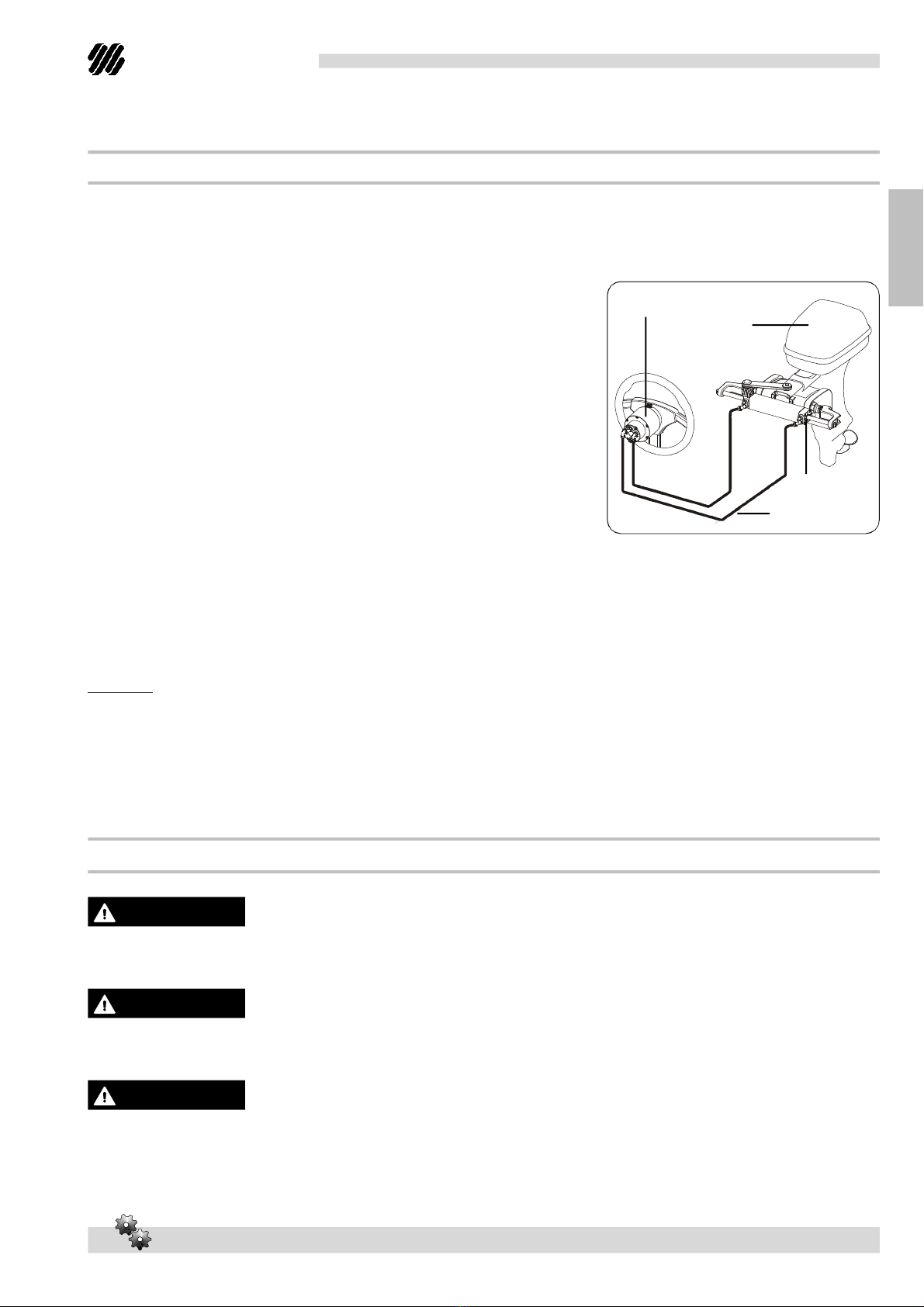
whichofferlonglifeandsafetyunderthemostextremeconditions. Ahydraulicsteeringsystemconsistsof
asteeringpumplocatedonthedashboard,acylindertiedtothe
rudderortotheoutboardorsterndriveengineandtheconnecting
hoses (seepicture).Undernormaloperatingconditions,aturnof
thesteeringwheelwill pumptheoil,whichflowsinthroughthe
hoses tothecylinder,accordingtotheturndirection.Withthe
consequentcylindermovementtheoilwill flowtothepumpthrough
thehoses andatthesametimemoves theengineorthehelmwhich
areconnectedtothecylinder.Thepumpsequippedwithanonreturn
valve, whichpreventsoutgoingfluidfromreturningalongthesame
hose. allowtheoperationofthesteeringsystemswithtwoormore
steeringstations.Thecylindersaredouble-actingandtheycanbe
balancedorunbalanced.Inunbalancedcylindersthetwochambers
havedifferentvolumes andthereforetheyrequireadifferentnumber
ofsteeringwheelturnsandadifferentsteeringwheelrotationeffort
withthe samemovementinthetwo directions. The balancedcylinders
requirethesamenumberofturnsofthesteeringwheeltomovethehelmfromthecentretotheendof
strokeinthetwoopposeddirections.
Awellbalancedsteeringsystemneedsacorrectchoiceofthepumpforthecylinder. ULTRAFLEX produces
differentpumpmodels,whichhavedifferentcapacity(cm3ofoilmovedeachsteeringwheelturn)andfor
eachtypeofinstallation.Whilechoosingthepumpitisimportanttoconsiderthecylindervolume.The
numberofstarboard andportturnsis determinedbytheratio betweenthecylindervolumeandthepump
capacity.
Example:ifthepumphas acapacityof28cm3 [1,7cu.in.]andthecylinderhas avolumeof120 cm3 [7,3cu.in.],the
formulalookslikethis: 120/28=4,2.Accordingly,thesteeringwheelwill turnabout4times beforethecylinder
willcompletelyturnfromonesidetotheother.Incase ofinstallationswithdoublecylindersconnectedin
parallelthecylindervolumemustbeadded.Applicationswithless than4turnsarenotrecommended,as
theyneedahighereffort,also applicationswithmorethan8turnsarenotrecommended,as theresponse
oftheboattosteeris slowly.
ULTRAFLEX steeringsystemsmustnotbeinstalledonraceboats.
All ULTRAFLEX steeringsystemsmustnotbeinstalledonboatsequippedwithengines whose maximum
horsepowerishigherthanthehorsepowerratingapprovedbyboatmanufacturer.
Do notmodifythepumpinanywaytofitittoyourapplication,otherwise thepumpwill nolongeroperatein
safetyanditwillendangertheboatandtheoccupants.
WARNING
WARNING
DANGER
l
engine
hydraulichoses
cylinder
l
l
l
pump

Installationandmaintenancemanual
ULTRAFLEX
page8 of71-PUMP FORHYDRAULICSYSTEMS
ENGLISH
1.3Systemconfigurations
ThepumpUP20canbeinstalledinasingleordoublesteeringsystemandusedwithdifferenttypes of
configurationsoffront,sideorinboardcylinders.
WARNING
Alwaysconnectthehosescorrectlyasindicatedintheinstallationandmaintenancemanualsofthe
correspondinghydrauliccylinders.
1.4Pumpdescription
ThepumpsUP20 FandUP20Thavebeendesignedandmanufacturedtobeusedasacomponentinthe
hydraulicsteeringsystems, as describedinthepreviousparagraph.ThepumpUP20Fmustbeinstalledon
thefrontpartoftheboatdashboardorsemi-built-inthroughflangeX74(suppliedseparately);thepump
UP20Tmustbeassembledbymeansoftilt X52 (suppliedseparately).Thefollowingpictures showthemain
pumpcomponents:
PumpUP20 F
Ventedtankplug
Steeringwheelconnectionshaft
Connectionstothecylinder
1
2
3
4
5
6
7
8
Connectionstotheadditionalstations
M8dowelsforfixingthepumpto thedashboard
PumpUP20T
Connectionshaft totiltX52
WARNING
ThepumpsmodelUP20canbeinstalledinasingleordoublesteeringsystemandusedwithcylinders
UC68, UC69, UC94.
UP20F
2
3
6
4
UP20T
1
7
2
8
4
5
5
44
5
5

PUMP FORHYDRAULICSYSTEMS - page9 of71
Installationandmaintenancemanual
ULTRAFLEX
ENGLISH
1.5Pumptechnicalfeatures
ThepumpUP20Tmustbeassembledonlybymeansoftilt X52 (suppliedseparately).
CAUTION
Thereleasepressureofthe
pressurereliefvalvesdoesnot
correspondtothesystem
normalpressurebutit
representsonlytheuselimits.
CAUTION
SPECIFICATIONS
PUMPUP20F
PUMPUP20T
Capacity 20 cc/rev. - 1,2 cu.in/rev. 20 cc/rev.- 1,2 cu.in/rev.
Pressurereliefvalve
releasepressure 70 bar(1000psi) 70 bar (1000 psi)
No. ofpistons 5 5
Max.steeringwheel
diameter 508 mm (20in.) 508 mm(20 in.)
Max.steeringwheel dish 114 mm(4,5 in.) 152mm (6in.)
Weight 3,6 kg (8lbs) 3,9 kg (8,5 lbs)
Oil OL150 Ultraflex OL150 Ultraflex
81,32 mm 3,2in.]
82 mm
[3,22 in.]
103,5mm
[4,1in.]
57,2mm
[2,3in.]
127 mm[5in.]
174 mm [6,8in.]
247 mm [9,7in.]
6°
Æ 120 mm[4.7in.]
Æ77 mm[3.03 in.]
UP20F
UP20T
76mm [3in.]
120 mm [4.7in.]
77 mm [3,03 in.]
19 mm [0,74 in.]
16 mm [0,62 in.]

Installationandmaintenancemanual
ULTRAFLEX
page10 of71-PUMP FORHYDRAULICSYSTEMS
ENGLISH
The packagingmustbe disposed ofaccording to theexisting laws.
2.1Generalwarnings
2TRANSPORT
ThepumpUP20 Fweightwithitspackagingis 4,5kg (9,92 pounds); thepumpUP20 T weightwithitspackaging
is 4,8 kg (10,58 pounds)andso theycanbehandledmanually.
2.2Packagingcontents
Beforeusingtheequipmentcheckthattheproducthasnotbeendamagedduringtransport.
Alsomakesurethatallthestandardcomponentsareinthepackaging(seelist).Incaseofdamage,
notifytheclaimtotheforwarderandinformthesupplier.
Thepackages contain:
A)pumpUP20 Fwithsealfordashboard fixing;
B)pumpUP20T;
C)forpumpUP20F:290°swivellingfittingstoconnecttheKitOB pipes (suppliedseparately);3nutsand3
washersforfixingthepumptothedashboard;1nut,1washer,1keyforsteeringwheeltightening;1
labelforplug;
D)forpumpUP20T:290°swivellingfittingstoconnecttheKitOBpipes (suppliedseparately);1labelfor
plug.
WARNING
Thestaff inchargeofhandlingmustoperatewithprotectivegloves andsafetyshoes.
CAUTION
A
D
B
C
UP20F UP20T

PUMP FORHYDRAULICSYSTEMS - page11 of71
Installationandmaintenancemanual
ULTRAFLEX
ENGLISH
3.2PumpUP20Finstallation
1Selectasuitableplaceforthesteeringstation.
Makesurethatthereis enoughmanoeuveringspace
forthesteeringwheelandforthesteeringpumpand
itspipes andfittings.
Inordertofixthepumpproperly,themaximum
dashboard thickness mustbe30 mm [1,18 in.].
Differentthicknesses could compromise thedriving
safety.Makesurethatthebreakingringofthe3self-
lockingnutssuppliedis engagedbythedowelthread.
WARNING
3INSTALLATION
3.1Toolsnecessary fortheinstallationofpumpUP20F
2Removetheplugs(1)fromthepump(2)byusinga
screwdriver.
3Screwthenutscompletelyonthecorresponding
90°unions(3),Fitandscrewtheunionsmanuallyas
indicatedinthepictureuntiltheyareinserted
completely.Turnthemuntiltheyarepositioned
correctlywithrespectto thepipes byunscrewingthem
nomorethanonerevolution,thentightenthenuts
witha11/16"Allenwrenchwithatorqueof17,6Nm
(13 lb ft) untilthewashertouches thenut.
DO NOT USEteflontapeoradhesivetape.
DONOTPUTanythreadsealantlikeLoctite542or
similarproducts.
WARNING
Torque
wrench Drill Openend
wrench
10 mm
Openend
wrench
11/16"
MOLYKOTE® 1000 Screwdriver
Openend
wrench
19 mm
1
2
1
min.82 mm [3,22 in.]
max.dashboard
thickness 30 mm[1,18
in.]]
System fitting
Connectionforadditional station
3
3Connectionfor
additional
station
System fitting

Installationandmaintenancemanual
ULTRAFLEX
page12 of71-PUMP FORHYDRAULICSYSTEMS
ENGLISH
5 Positionthe pump(2)onthe dashboard front
side(6)interposingthegasket(7)andfix itby
insertingthe3washers(8)andbytightening
the3self-lockingnuts(9)witha10 mm wrench
andatorqueof8Nm(5,90 lbft).
WARNING
Installthepumpbypositioningthefillinghole
(10)towards thetop(see the picture)fortheright
pumpoperationandtoallowfillingandpurging
thesystemcompletely(see par.3.7).
6Positionthesteeringwheelsupplied
separately(11)onthepumpshaft(12)byusing
thesuitablekey(13).Insertthewasher(14)and
tightentheself-lockingnut(15)witha19"open
endwrenchandwithatorqueof30Nm(22,14
lbft);thengrease the threadbyusingsome anti-
seizegrease MOLYKOTE® 1000 orasimilar
one.
4Byusingthepropertemplatesuppliedwith
thismanual,makethe3holes(4)forthe3
dowelsandthecentralhole(5).
If theself-lockingnuts aredisassembled(9),they
mustbereplaced.(Contactourassistance
service,seepage6).
CAUTION
If theself-lockingnut(15)is disassembled,itmust
bereplaced.(Contactourassistanceservice, see
page6).
CAUTION
2
8
9
6
10
4
12
11
14
15
13
7
8
8
9
9
5

PUMP FORHYDRAULICSYSTEMS - page13 of71
Installationandmaintenancemanual
ULTRAFLEX
ENGLISH
3.4PumpUP20Tinstallation
1Selectasuitableplaceforthesteering
station.Makesurethatthereisenough
manoeuveringspaceforthesteeringwheeland
forthesteeringpumpanditspipes andfittings.
3Fix thebracket(3)suppliedwithtilt X52 tothe
dashboard (4)byfollowingtheinstructions
enclosedtotiltX52.
3.3Toolsnecessary fortheinstallationofpumpUP20T
*Thetoolstoassembletilt X52 arelisted
inthemanualenclosedtotilt X52.
Screwdriver
Thetilt X52 mechanismis suppliedseparately.
NOTICE
2Removetheplugs(1)fromthepump(2)byusinga
screwdriver.
Openend
wrench
13 mm
4
3
12°
12°
12°
12°
min.255 mm [10,03 in.]
1
2
1

Installationandmaintenancemanual
ULTRAFLEX
page14 of71-PUMP FORHYDRAULICSYSTEMS
ENGLISH
DO NOT USEteflontapeoradhesivetape.
DO NOT PUT anythreadsealantlikeLoctite542
orsimilarproducts.
WARNING
4Screwthenutscompletelyonthe
corresponding90°unions(3),Fitandscrewthe
unions manuallyas indicatedinthe picture until
theyareinsertedcompletely.Turnthemuntil
theyarepositionedcorrectlywithrespectto
thepipes byunscrewingthemnomorethan
onerevolution,thentightenthenutswitha11/
16"Allenwrenchwithatorqueof17,6 Nm(13
lb ft) untilthewashertouches thenut.
5 Fix the pumptothebracket(3)suppliedwith
tiltX52byusingthe3M8screws(6)supplied
withtilt X52 accordingtotheinstructionsenclosed
totilt X52.
WARNING
Installthepumpbypositioningthefillinghole
(7)towardsthetop(see thepicture)fortheright
pumpoperationandtoallowfillingandpurging
thesystemcompletely(see par.3.7).
System fitting
Connectionforadditional station
System fitting
3
6
7
5
5
Connectionfor
additional
station

PUMP FORHYDRAULICSYSTEMS - page15 of71
Installationandmaintenancemanual
ULTRAFLEX
ENGLISH
6Alignandinsertthetilt universaljointinto
thepumpshaft bylooseningabout1-1.5turns
thescrews(8)ontheuniversaljointitself always
accordingtotheproceduredescribedinthe
installationmanualsuppliedwithtilt X52.
Retightenthescrews(8)(small screwtorqueof
3Nm-26 lbsin,bigscrewtorqueof7,5 Nm-
68 lbsin)andfix thetilt withscrews(9)(torque
of5Nm-44 lbsin).
NOTICE
ThekitF ULTRAFLEX suppliedseparately(see thecorrespondinginstructions)canbeusedonpumpUP20T
tosimplifythehydraulicsystemfillingandpurging.
8
8
99
9

Installationandmaintenancemanual
ULTRAFLEX
page16 of71-PUMP FORHYDRAULICSYSTEMS
ENGLISH
3.6 Hoseconnectiontothesystem
1Connectthehydraulichoses ULTRAFLEX kitOB (suppliedseparately)joiningthepumpandthecylinder
byfollowingtheinstructionsgivenintheinstallationmanualofthekitOB.
2If oneormoreadditionalsteeringstationsareinstalled,use thekitOB-2Sorthekit95-2byfollowing
thesuitableinstructions.
WARNING
Connecthoses as shownintheinstallationandmaintenancemanualofthecorrespondinghydrauliccylinders.
3.5Typesofinstallation
ThepumpmodelUP20 canbeinstalledinasingleordualstationandtheycanbeusedwithdifferenttypes
offrontmount,sideorinboardcylinderconfigurations.
WARNING
ThepumpsmodelUP20 canbeinstalledinasingleordoublesteeringsystemandusedwiththecylinders
UC68, UC69, UC94.
Themainsteeringstationis theonlyonewhichis equippedwithventpluganditis alwaystheoneplaced
inthehigherposition.Theadditionalsteeringstationorpossibleotherstationsmustbeplacedbelowthe
mainsteeringstationandequippedwithplugwithoutvent.
CAUTION
Unscrewtheplugs(2),putonlystraightfittingscode43179P(includedintheOB-2Skit) (1)onthepumpsas
showninpicture.
ApplyLoctite542 orLoctite545 sealantonthreadsofthefitting,then,fitandscrewthem(1)manuallyuntil
theyarecompletelyinserted,thentightenwitha9/16"hexagonalwrenchwithatorqueof12 Nm(8.8 lb ft).
Do notuse teflontapeoranyotheradhesivetape. Applyfittingsealantprescribed.
WARNING
1.mainsteeringstation
2.additionalsteeringstation
3.kitOB
4.fittingskitOB-2Sorkit95-2S(not
suppliedwithcompensationhose)
5.ventplug(blackplug)
6.plugwithoutvent(greyplug,included
inthekitOB-2Set95-2S)
NOTICE
KitOB-2S(orkit95-2S)is supplied
separatelyincaseofapplicationswith
doublestation.
1
2
4
5
6
33
3
3

PUMP FORHYDRAULICSYSTEMS - page17 of71
Installationandmaintenancemanual
ULTRAFLEX
ENGLISH
MAINSTEERINGSTATION ADDITIONALSTEERINGSTATION
3Connectpipes as showninpicturefollowingthemanualinstructions.
Atthe endofthe installationmake sure thatthepipes do notinterfere
withtheengineandwithfixedormobilepartsoftheboatorofthe
steeringsystemitself.
WARNING
Theminimumbendingradiusofthepipes is 250 mm.Anyexcessive
pipebendingcould breakthembycompromisingthegoodoperation
ofthesystem.Ifnecessary,replacethedamagedpipe.
WARNING
Keepclean.Makesurethatworkingareas arefreefromdustanddirt.
Theprotectiveplugsofthreadedholes mustberemovedonlybefore
theconnectionoffittingsandpipes. Makesurethatpipes areperfectly
cleanandfree fromswarf.If copperorsteelpipes areused,cleaning
is mandatory.If theinstalleruses pipes thataredifferentfromKitOB,
hemusttakefull responsibilityforit.
WARNING
WARNING
Keepthepipes farfromheatsources andfromchemicalsubstances.
Protectthepipes thatmustpass throughbulkheadsbyusingsuitable
thruhulls. Thebendsmustbeperfectlysmooth;anybentpipeor
dentwould preventthehydraulicoilpassage.
NO
Minimumradius 250 mm
11
2
2
KitOB
cylinder
connecting
pipe
KitOB-2S KitOB
cylinder
connecting
pipe
KitOB
cylinder
connecting
pipe
KitOB-2S

Installationandmaintenancemanual
ULTRAFLEX
page18 of71-PUMP FORHYDRAULICSYSTEMS
ENGLISH
3.7Fillingandpurging
Afterthefirstinstallationandaftermaintenanceoperationsitis necessarytofill thesystemwithhydraulic
oil.Thisoperationmustavoidtheairinthesystem,toensurethegoodsystemoperation.Thehydraulic
systemmustbefilledfromthehighestpointofthesystem,whichmeansfromtheuppersteeringstation.
CAUTION
WARNING
To avoidairbubblesintheoil,itis necessarytofillthetankslowly.
Thefillingandbleedingoperationsmustbecarriedoutatleastbytwooperators
DANGER
Use ULTRAFLEX oilorothercompatibleoils.
NOTICE
ThefillingandpurgingoperationscanbefacilitatedbyusingtheautomaticpurgingequipmentBUBBLE
BLUSTERâ (suppliedseparately).
HydraulicoilOL150 has beenspecificallyformulatedfor ULTRAFLEX toensurehighqualityperformance
levelof ULTRAFLEX productsthroughouttime.
Itsspecial"ZincFree"formulaenhances protectionagainstmarineoxidation.Thespecialmix ofanti-wear
andstabilizingcomponentsofOL150 allowensuringgreatresultsas farastheproductdurationand
performances areconcernedinseveralenvironmentalconditions. ULTRAFLEX hydraulicoilcomplies with
standard ISO10592 concerninghydraulicsteeringsystems. ULTRAFLEX is nottobeheld responsibleforany
damages orperformancedeteriorationifoilsdifferentfromOL150 areused.
Do NOT use ATFDexronII transmissionoilsorbrakeoilswhichcould cause thesteeringsystemseizing.
OilswhicharecompatiblewithOL150 ULTRAFLEX are:
-Shell TellusT15 andShell TellusT22
-MobilDTE11M
-Q8 HAYDN15
DANGER
ULTRAFLEX willnotbeabletoensurethecompatibilityoftheabovementionedoilswithOL150iftheoil
manufacturersvarytheirformulation;inparticular,itwill notbeabletoensureitscompliancewithstandard
ISO 10592 concerninghydraulicsteeringsystems. Undernocircumstances ULTRAFLEX is tobe held responsible
foranydamagesorperformancedeterioration.
Inthedaysafterthefilling,checktheoillevel;ifnecessarytopoff thesystem.
Atthebeginningtheoillevelcanlower,assmallamountsofaircanbereleasedinahomogeneousway.
Accordingtothetypes ofinstallation,itis necessarytocarryoutthedifferentbleedingprocedures, as itfollows.
NOTICE

PUMP FORHYDRAULICSYSTEMS - page19 of71
Installationandmaintenancemanual
ULTRAFLEX
ENGLISH
3.8Generalrecommendation
3.7.2Purgingprocedure
3.7.1Positioningoftheoil bottle
-Removethepumpcapandinsertthefittings.
- Attachthespouttoanewbottleofhydraulicoilandconnectthehose to
thefittingsandthebottlespout.
-Turnthebottleupsidedownandpierceitwiththepin,as showninthe
picture,toease theoilpassagetowardsthepump.
Fill thepumpuntilnoairbubbles arevisibleinthehose.
pin
oilbottle
transparent
hose
Whilereplacingtheoilbottle,duringthefillingprocess, close allthebleed
valves ofthecylinder/s. To bleedthesystem,checkthatoilis alwayspresent
inthefillinghose. If someairis inthesystemduringthebleedingprocess,
thewholebleedingprocess mustbestartedagain.
WARNING
Replacethebottlebeforeitempties anduse recoveredoilonlyafter24
hours.
CAUTION
NOTICE
Carryoutthepurgingprocedureasindicatedintheinstallationandmaintenancemanualofthecylinder
used.Thencheckthattheoillevelis suitablebyturning1/2turnthesteeringwheelandbymakingtheoil
comeoutofthebleedvalve.Closethevalveandcheckthesystem.
spout
fillinghose
holder
connection
It is veryimportanttochecktheabsenceofairinthesystembeforeusingtheboat! Werecommendtrying
tomanuallymovetheengine/sorthehelm/stowardsportandstarboard,makingsurethatthereis no
movementofthecylinderbodyonthemaincylindershaft.
Ifthecylinderbodymovestoomuch,thereisstillairinthesystem.Theairpresenceinthesystemcan
causebadresponses tothecontrolsandso itcancause damage, injuriesordeath.
WARNING
DANGER
After24 hoursrepeatthepurgingandmakesuretherearenoleaks.
WARNING
Checkthesystemresponse bymovingthepump.
To carryoutthis operation,itis necessarytouse theoilfillingkit(1needle,
1transparentpipe, 1pipeconnectionand1spoutfortheoilbottle).This kit
isNOTsupplied.

Installationandmaintenancemanual
ULTRAFLEX
page20 of71-PUMP FORHYDRAULICSYSTEMS
ENGLISH
ATTENZIONE
4SAFETYWARNINGS
Thissectionshowsthesafetyruleswhichmustbefollowedforthecorrectequipmentoperation.
Werecommendreadingcarefullythis sectionandalso theothermanualssuppliedwiththesteeringsystem
components.
4.1Safetywarningsduringuseandinstallation
RESPECTSTRICTLYthefollowingsafetyrules.
ULTRAFLEX declines all responsibilityincase theuserdoes notfollowthese rules anditis notresponsible
fornegligenceduringtheuse ofthesystem.
-DO NOT PUT HANDSBETWEENTHEMOVINGPARTS.
-Do notdisablethesafetydevices.
- Do notmodifyoradd devices tothesystem,without ULTRAFLEX writtenauthorisationortechnical
interventionwhichwillprovethemodification.
-Do notuse theequipmentforapurpose differentfromtheoneithas beendesignedfor,whichis
specifiedintheinstallationandmaintenancemanual.
-Do notletnon-specializedstaff performtheinstallation.
-Donotdisassemblethehydraulicconnectionsbeforebleedingtheoilinthesystemcompletely.
Thehoses cancontainhighpressureoil.
- Incase ofinstallationwithdoublestationDO NOTuse bothstations. As amatteroffactthetwo
stationsarealwaysenabledonthesteeringcompartment.Theeffectoftheruddenrotationon
bothstationswilldoublecausinganundesiredmanoeuvre.
!
DANGER
WARNING
-Do notputthefeetonthecylinder.
-Checkthesystemaftertheinstallationandthepurgingbutbeforeoperatingthevessel.Turnthe
steeringwheeluntilthecylinder/sreaches/reachtheendstroke.
Turnthesteeringwheeltotheoppositedirection.Repeatoneachinstalledhelmtoverifythe
correctinstallationandthesystemoperation.
-Carefullyuse sealingfluid(suchasLoctite).If itreaches thehydraulicsystem,itmaycause
damageandmechanicalfailure.
-Do notuse teflontapeoradhesivetapetosealthefittings,as this materialmaybeinjested,by
causingthesystemfail.
-Duringthesysteminstallation,preventforeignmattersfromenteringthesystem.
Evenalittleobjectmaycause lastingdamagethatarenotdetectedimmediately.
-Avoidtoo narrowbendradiusofhoses.
- Avoidthehosecontactwithedgesorsharp corners.
- Avoidthehosecontactwithheatsources.
Duringinstallation,inspectionormaintenance, ITISSTRICTLYFORBIDDENtowearnecklaces, braceletsor
clothes whichcould getcaughtinthemovingparts.
4.2Clothing
WARNING
This manual suits for next models
1
Table of contents
Languages:
Other Ultraflex Water Pump manuals
Popular Water Pump manuals by other brands

Cembre
Cembre B70M-P36 Operation and maintenance manual

Andritz
Andritz SU8 Series operating instructions

Steinbach
Steinbach SPS 175-1T ORIGINAL OWNER'S MANUAL

Teral
Teral PL Series instruction manual

BLACKMER
BLACKMER SMVP15B Installation, operation and maintenance instructions

Test Equipment Depot
Test Equipment Depot NRP6Di user guide

Patterson
Patterson HSC Operation and maintenance

SFA
SFA SANIFOS 1600 operating instructions

Hilti
Hilti DD VP-U operating instructions

Grundfos
Grundfos PACOpaQ Installation and operating instruction manual

Dover
Dover Wilden Advanced P400 Engineering, operation & maintenance

Booster
Booster HSPJ100 quick start guide