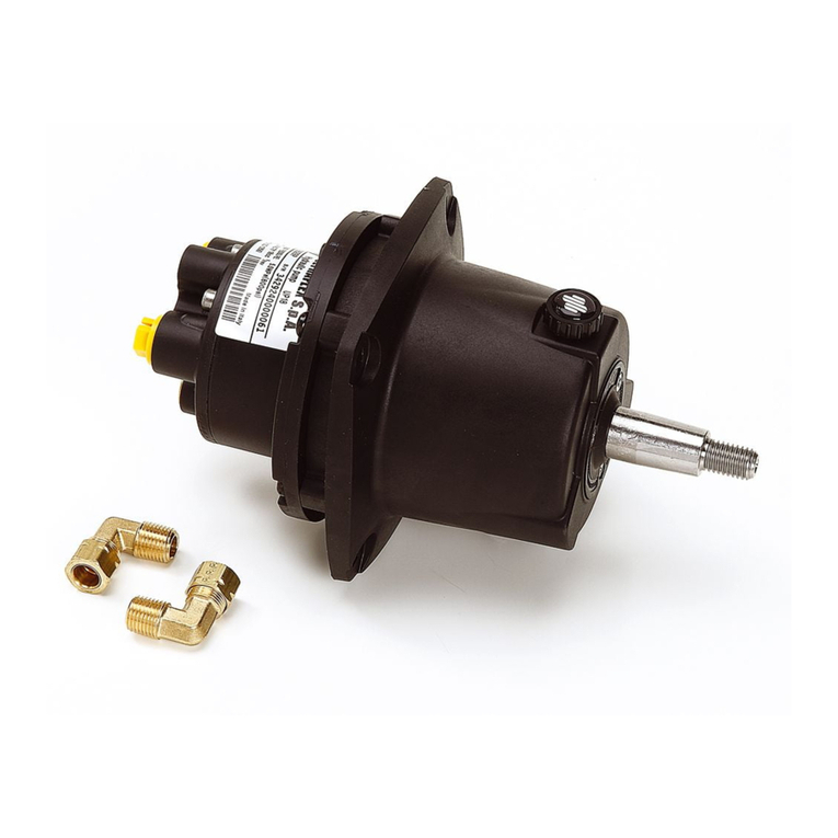
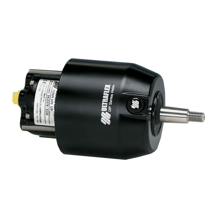
Ultraflex UP 56 Manual

PUMPFORHYDRAULIC
STEERINGSYSTEMS
UP56
UP68
ULTRAFLEX
SOCIO
InstallationandMaintenanceManual
R
ITALIANOFRANÇAIS ENGLISH
I
UK F
page 2 pag.25 page. 49
(Dr.No.22825/d08/05/2015)

ULTRAFLEX S.p.A.
ULTRAFLEX
16015 Casella (Genova)Italia-ViaCrose,2
"ULTRAFLEX has over80 yearsofexperienceinthemarineindustryandis aworld leaderintheproduction
ofmechanical,hydraulicandelectronicsteeringsystems,controlboxesandsteeringwheelsforany
kindofpleasure,fishingorcommercialboats.
Thekeyfactorswhichexplaintheincreasingsuccess ofourproductsall overtheworld arethereliability
ofourproductsandthebeforeandaftersaleservice, thequalityofthecompanyorganizationandofthe
humanresourcesandthecontinuousspendinginresearchanddevelopment".
DearCustomer,
Wewouldliketothankyouforchoosingan ULTRAFLEX product.
ULTRAFLEX has beenaleaderinsteeringsystemsforpleasureandprofessionalboatsformanyyears.
ULTRAFLEX productionis sinceeversynonimousofreliabilityandsafety.
All ULTRAFLEX productsaredesignedandmanufacturedtoensurethebestperformance.
Toensureyoursafetyandtomaintainahighqualitylevel, ULTRAFLEX productsareguaranteedonlyif
theyareusedwithoriginalspareparts.
ULTRAFLEX and UFLEX QualityManagementSystemsarecertifiedCISQ-IQNetbytheItalianShipping
Registry(RINA),inconformitywiththeUNIENISO9001:2008rule. ULTRAFLEX certificationNo. 6669/02/S
(former420/96). UFLEX certificationNo. 8875/03/S.
Thequalitymanagementsysteminvolvesallthecompanyresourcesandprocesses startingfromthe
design,inorderto:
- ensureproductqualitytothecustomer;
-maintainandimprovethequalitystandardsconstantly;
-pursueacontinuousprocess improvementtomeetthemarketneedsandtoincrease thecustomer
satisfaction
ULTRAFLEX EnvironmentalManagementSystemiscertifiedCISQ-IQNetbytheItalianShippingRegistry
(RINA),inconformitywiththeUNIENISO14001rule. ULTRAFLEX certificationNo.EMS-1282/S.
Productsforpleasureboatsareconstantlytestedtochecktheirconformitywiththe2013/53/EU.

PUMP FORHYDRAULICSYSTEMS -page3 of75
InstallationandMaintenanceManual
ULTRAFLEX
ENGLISH
SECTION1-PRODUCTDESCRIPTION
1.1 HYDRAULICSTEERINGSYSTEMOPERATION..................................................................................7
1.2 WARNINGSFORTHECORRECTPRODUCTUSE.....................................................................7
1.3 SYSTEMCONFIGURATIONS........................................................................................................................8
1.4 PUMPDESCRIPTION..............................................................................................................9
1.5 PUMPANDPRESSURERELIEFVALVETECHNICALFEATURES............................................................9
TABLEOFCONTENTS
SECTION2-TRANSPORT
2.1 GENERALWARNINGS............................................................................................................................10
2.2 PACKAGINGCONTENTS....................................................................................................................10
SECTION5-MAINTENANCE
5.1 ORDINARYMAINTENANCE................................................................................................................22
5.2 TROUBLESHOOTING.........................................................................................................................22
SECTION3-INSTALLATION
3.1 NECESSARY TOOLSFOR REAR MOUNTINSTALLATION.....................................................................12
3.2 REARMOUNTINSTALLATION(WITHKITKR56)......................................................................12
3.3 NECESSARYTOOLSFOR INTERMEDIATEINSTALLATION.......................................................................14
3.4 INTERMEDIATEINSTALLATION(WITHKITKR56).........................................................................14
3,5 HOSECONNECTIONTO THESYSTEM....................................................................................................16
3,6 TYPEOFINSTALLATION.........................................................................................................................17
3.7 FILLINGANDPURGING.......................................................................................................................18
3,7,1 SINGLESTEERINGSTATION/SINGLE CYLINDER.....................................................................................19
3.7.2 DUALSTEERINGSTATION/SINGLECYLINDER.........................................................................................20
3.8 GENERALRECOMMENDATIONS................................................................................................................20
SECTION4-SAFETYWARNINGS
4.1 SAFETYWARNINGSDURINGUSEANDINSTALLATION.......................................................................21
4.2 CLOTHING....................................................................................................................21
SECTION6-DISMANTLING
6.1 DISMANTLING.......................................................................................................................24
!
DOCUMENTREVISIONS...................................................................................................................................4
MANUALUSEANDSYMBOLSUSED................................................................................................................5
INTRODUCTION.................................................................................................................................6
WARRANTY................................................................................................................................6

InstallationandMaintenanceManual
ULTRAFLEX
page4 of75-PUMP FORHYDRAULICSYSTEMS
ENGLISH
DOCUMENTREVISIONS
Rev. Date Revisiondescription
0
A
B
13/04/2006
24/09/2013
16/07/2014
Firstedition
AdditionofUP68 model, additionofthe rearmount and intermediate
installationdescription
Modificationofchapter"Packagingcontents"

PUMP FORHYDRAULICSYSTEMS -page5 of75
InstallationandMaintenanceManual
ULTRAFLEX
ENGLISH
Inthis manualthefollowingsymbolsareusedtoensuretheusersafetyandtoguarantee thecorrect
operationoftheproduct:
MANUALUSEANDSYMBOLSUSED
THEINSTALLATIONANDMAINTENANCE MANUALis thedocumentaccompanyingtheproductfromitssale
toitsreplacementanddischarge.Themanualis animportantpartoftheproductitself.
It is necessarytoreadcarefullythemanual,beforeANYACTIVITY involvingtheproduct,handlingand
unloadingincluded.
STERN
BOW
STARBOARD PORT Thepictureasideexplainsthemeaningofsome
nauticalwordscontainedinthismanual.
DANGER ImmediatehazardswhichCAUSEseverepersonalinjuryordeath.
WARNING
CAUTION
Thesymbolasideindicates all theoperationswhichmustbecarriedout
byqualifiedorskilledstaff,inordertoavoidhazards.
Werecommendtrainingthestaff inchargeoftheproductinstallation
andcheckingtheirknowledge.
NOTICE Importantinformationforthecorrectinstallationandformaintenance,that
doesnotcauseanydamage.
Denotes thatahazard existswhichcanresult ininjuryordeathifproper
precautionsarenottaken.
Denotes areminderofsafetypracticesordirectsattentiontounsafe
practices whichcould result inpersonalinjuryordamagetothecraft or
componentsortotheenvironment.

InstallationandMaintenanceManual
ULTRAFLEX
page6 of75-PUMP FORHYDRAULICSYSTEMS
ENGLISH
WARRANTY
ULTRAFLEX guarantees thatitsproductsarewell designedandfree frommanufacturingandmaterialdefects,
foraperiodoftwoyearsfromthedateofmanufacturing.
Fortheproductswhichareinstalledandusedonworkingorcommercialboatsthewarrantyislimitedto
oneyearfromthedateofmanufacturing.
Ifduringthis periodtheproductproves tobedefectiveduetoimpropermaterialsand/ormanufacture, the
manufacturerwill repairorreplacethedefectivepartsfree ofcharge.
Directorindirectdamageis notcoveredbythis warranty.Inparticularthecompanyisnotresponsibleandthis
warrantywillnotcoverthedamageresultingfromincorrectinstallationoruseoftheproduct(exceptfor
replacementorrepairofdefectivepartsaccordingtotheconditionsandtermsabove).
This warrantydoes notcovertheproductsinstalledonraceboatsorboatsusedincompetitions.
Thedescriptionsandillustrationscontainedinthis manualshouldbeusedas generalreferenceonly.
ForanyfurtherinformationpleasecontactourTechnicalAssistanceService.
ULTRAFLEX steeringsystemcomponentsaremarkedaccordingtotheDirective2013/53/EU.
Weremindyouthatonly markedsteeringsystemsmustbeusedontheboatsmarked.
Weinformyouthatthe ULTRAFLEX warrantyis null ifsomeULTRAFLEX componentsareinstalledonasteering
systemtogetherwithproductsofotherbrands.
TECHNICALASSISTANCE SERVICE
INTRODUCTION
UFLEX S.r.l.
ViaMiliteIgnoto,8A
16012 Busalla(GE)-Italy
Tel:+39.010.962.0239(Italy)
Tel:+39.010.962.0244(abroad)
Fax: +39.010.962.0333
Email:ut@ultraflexgroup.it
www.ultraflexgroup.it
North-South-CentralAmerica:
UFLEX USA
6442 ParklandDrive
Sarasota, FL34243
Ph.:+1.941.351.2628
Fax: +1.941.360.9171
Email:uflex@uflexusa.com
www.uflexusa.com
This installationandmaintenancemanualrepresentsanimportantpartoftheproductandmustbeavailable
tothepeopleinchargeofitsuse andmaintenance.
Theusermustknowthecontentofthis manual.
ULTRAFLEX declines allresponsibilityforpossiblemistakes inthismanualduetoprintingerrors.
Apartfromtheessentialfeaturesofthedescribedproduct, ULTRAFLEX reserves therighttomakethose
modifications, suchas descriptions, detailsandillustrations, thatareconsideredtobesuitableforits
improvement,orfordesignorsales requirements, atanymomentandwithoutbeingobligedtoupdatethis
publication.
ALLRIGHTSARERESERVED.Publishingrights,trademarks,partnumbersandphotographsof ULTRAFLEX
productscontainedinthismanualare ULTRAFLEX property.
Greatcarehas beentakenincollectingandcheckingthedocumentationcontainedinthismanualto
makeitas completeandcomprehensibleas possible. Nothingcontainedinthis manualcanbeinterpreted
as warrantyeitherexpressedorimplied-including,notinarestrictedway,thesuitabilitywarrantyforany
specialpurpose. Nothingcontainedinthis manualcanbeinterpretedas amodificationorconfirmationof
thetermsofanypurchase contract.
Toensurethecorrectproductandcomponentoperation,theproductmustbeinstalledbyqualifiedstaff.
Incaseofpartdamageormalfunction,please contactthequalifiedstafforourTechnicalAssistance
Service.
WARNING

PUMP FORHYDRAULICSYSTEMS -page7 of75
InstallationandMaintenanceManual
ULTRAFLEX
ENGLISH
TheUP56-UP68 pumpmustnotbeinstalledonraceboats.
TheUP56-UP68 pumpisprovidedwith(external)pressurereliefvalve(seepictureabove)thatmustbe
placedabsolutelybetweenpumpandcylinderasshownintheparagraph3.5.
All ULTRAFLEX steeringsystemsmustnotbeinstalledonboatsequippedwithengines whosemaximum
horsepowerishigherthanthehorsepowerratingapprovedbyboatmanufacturer.
1.2Warningsfortheproductcorrectuse
Donotmodifythesteeringcylinderinanywaytofitittoyourapplication,otherwise thecylinderwillno
longeroperateinsafetyanditwill endangertheboatandtheoccupants.
WARNING
WARNING
WARNING
DANGER
1PRODUCTDESCRIPTION
1.1Hydraulicsteeringsystemoperation
All ULTRAFLEX hydraulicsteeringsystemsaredesignedinconformitywithUNI-EN-ISO10592 andA.B.Y.C.P21
regulations. All ULTRAFLEX steeringsystemscanoperateattemperatures between-18°C(0°F)and+77°C(+170°F).
Allthecomponentsaremadeforthemarineenvironment,usingmaterialsandworkingprocesses which
offerlonglifeandsafetyunderthemostextremeconditions. Ahydraulicsteeringsystemconsistsofa
steeringpump,acylindertiedtotherudderortotheoutboardor
sterndriveengineandtheconnectinghoses (see picture).Undernormal
operatingconditions, aturnofthesteeringwheelwill pumptheoil,
whichflowsinthroughthehosestothecylinder,accordingtotheturn
direction.Withtheconsequentcylindermovementtheoilwill flowtothe
pumpthroughthehoses andatthesametimemoves theengineorthe
helmwhichareconnectedtothecylinder.Thepumpsareequipped
withavalve, whichpreventsoutgoingfluidfromreturningalongthe
samehose. It also allowstheoperationofthesteeringsystemswithtwo
ormoresteeringstations.Thecylindersaredoubleactingandmaybe
balancedorunbalanced.Intheunbalancedcylindersthetwochambers
havedifferentvolumes andso theyneedadifferentnumberofturnsof
thesteeringwheelandadifferentrotationeffort.Thebalancedcylinders
havesamenumberofsteeringwheelturnsinordertomovethehelm
fromthecentertotheendstrokeinthetwooppositedirections. Awell
balancedsteeringsystemneedsacorrectchoiceofthepumpforthe
cylinder. ULTRAFLEX produces differentpumpmodels,whichhavedifferentcapacity(cm3ofoilmovedeach
steeringwheelturn)andforeachtypeofinstallation.Whilechoosingthepumpitisimportanttoconsider
thecylindervolume. Thenumberofstarboard andportturnsis determinedbytheratio betweenthecylinder
volumeandthepumpcapacity.
Example:ifthepumphas acapacityof28cm3 [1,7cu.in.]andthecylinderhas avolumeof120 cm3 [7,3cu.in.],the
formulalookslikethis: 120/28=4,2.Accordingly,thesteeringwheelwill turn4,2 times beforethecylinderwill
completelyturnfromonesidetotheother.Incase ofinstallationswithdoublecylindersconnectedin
parallelthecylindervolumemustbeadded.Applicationswithless than4turnsarenotrecommended,as
theyneedahighereffort,alsoapplicationswithmorethan8turnsarealsonotrecommended,asthe
response oftheboattosteeris slowly.Themaximumoperatingpressureis 7,0MPa(70 bar)(1000 PSI).
pump
l
l
hydraulichose
l
cylinder
helm
l
l
pressurereliefvalve

InstallationandMaintenanceManual
ULTRAFLEX
page8 of75-PUMP FORHYDRAULICSYSTEMS
ENGLISH
NOTA
Ifitis necessarytousetwoUP56-UP68 pumpsindualstation,please contactourTechnicalAssistance
Service(see page6)inordertohaveanyinformationaboutthenecessarycomponentsandtheinstructions
tobefollowedfortheinstallation.
1.3Systemconfigurations
ThepumpUP56-UP68 modelcanbeinstalledinasingleordualenginesteeringsystemanditcanbeused
withdifferentcylinderconfigurations.Thepossibleconfigurationsare:
STEERINGSTATION
NUMBER
S
I
N
G
L
E
S
T
A
T
I
O
N
HELMNUMBER
With
SINGLE CYLINDER
upto300hpmax
MAIN STATION
ADDITIONAL
STATION
D
U
A
L
S
T
A
T
I
O
N
S
I
N
G
L
E
H
E
L
M
NOTICE
With
SINGLE CYLINDER
and
TIEBAR
non-counterrotating
engines upto
300hpmax of
combinedhorsepower
counterrotating
engines upto450hp
max ofcombined
horsepowerandupto
55 m.p.h.
D
U
A
L
H
E
L
M

PUMP FORHYDRAULICSYSTEMS -page9 of75
InstallationandMaintenanceManual
ULTRAFLEX
ENGLISH
1.4Pumpdescription
UP56-UP68 is a pumpwhichhas beendesignedandmanufacturedtobe usedas a componentinthe hydraulic
steeringsystems, as describedinthepreviousparagraph.
Thepumpmustbeinstalledonthebackpartoftheboatdashboard.
Thesteeringwheelismounteddirectlyonthehubofthepump.Inordertoguaranteetheboatsteering
undersafetyconditions,thepumpisprovidedwithacheckvalve.Thefollowingpictureshowsthemain
pumpcomponents:
Pump
Checkvalve
Steeringwheelshaft
Oilfillingcap
Coverglass foroillevelcheck
Systemfitting
Systemfitting
Connectionsforadditionalstations
Washer
Nutforfixingthesteeringwheel
ontheshaft
O-ring*
KR56 bezel*
ScrewsforfixingtheKR56 bezel*
*{KitKR56notincluded-code42558T}
1
2
3
4
5
6
7
8
9
10
11
1.5Pumpandpressurereliefvalvetechnicalfeatures
151 mm [5,94 in.]
151 mm [5,94 in.]
123 mm [4,84 in.]
26 mm
[1,02 in.]
117mm
[6,73 in.]
188mm
[7,40 in.]
25 mm [0,98 in.]
19,05 mm [3/4in.]
5/8 in.-18 UNF
62 mm
[2,44 in.] 70 mm
[2,75 in.]
62,2mm
[2,44 in.]
ThepumpmodelUP56-UP68 mustbeusedonlywiththecylindersmodelUC378, UC339-I,UC442-IandUC530-I.
NOTICE
12
13
KIT KR56bezel
-code42558T
(notincluded)
70 mm
[2,75 in.]
55 mm
[2,16 in.]
35 mm
[1,37 in.]
2
6
7
8
8
10
9
13
12
11
3
5
4
1
PressurereliefvalveRV70-
code42560D(notincluded)
SPECIFICATION
PUMPUP56
PUMPUP68
Capacity 56cc/rev. -3,4cu.in/rev. 68 cc/rev. -4,15 cu.in/rev.
Max. operating
pressure 70bar(1000 psi) 70 bar(1000 psi)
Piston No. 7 7
Max. steering wheel
diameter 711 mm (28in.) 711 mm (28 in.)
Steering wheelheight 152mm (6in.) 152 mm (6in.)
Weight 8kg 8kg
Oil OL150Ultraflex OL150 Ultraflex

InstallationandMaintenanceManual
ULTRAFLEX
page10 of75-PUMP FORHYDRAULICSYSTEMS
ENGLISH
2.1Generalwarnings
2TRANSPORT
Theproductweightwithitspackagingis 9kg (19,84 pounds)andso itcanbehandledmanually.
2.2Packagingcontents
Beforeusingtheequipmentcheckthattheproducthasnotbeendamagedduringtransport.
Alsomakesurethatallthestandardcomponentsareinthepackaging(seelist).Incaseofdamage,
notifytheclaimtotheforwarderandinformthesupplier.
PUMPS UP56 -UP68:
A)pump;
B)pumpfittingsforpipe/hose Æ12mm;
C)nut,washandkeyfortighteningthesteeringwheelontheshaft;
D)adapter;
WARNING
Thestaff inchargeofhandlingmustoperatewithprotectivegloves andsafetyshoes.
KIT KR56 (NOT INCLUDED -CODE42558T):
E)screws, washes andnutsforfixingthepumptothedashboard;
F)KR56 bezel;
EF
A
C
B
D

PUMP FORHYDRAULICSYSTEMS -page11 of75
InstallationandMaintenanceManual
ULTRAFLEX
ENGLISH
KIT KIM56 (NOT INCLUDED-CODE42559V):
G)screws, washes andnutsforfixingthepumptothedashboard;
G
RV70 (NOT INCLUDED -CODE42560D):
H)pressurereliefvalvefittingsforpipe/hose Æ12mm;
I) pressurereliefvalve.
I
H
The packagingmustbe disposed ofaccording to theexisting laws.
CAUTION

InstallationandMaintenanceManual
ULTRAFLEX
page12 of75-PUMP FORHYDRAULICSYSTEMS
ENGLISH
3.2Rearmountinstallation(withKITKR56)
1Selectasuitableplaceforthesteeringstation.
Makesurethatthereis enoughmanoeuveringspace
forthesteeringwheelandforthesteeringpumpand
itspipes andfittings.
Inordertofix thepumpproperly,thedashboard
thickness mustbebetween17 and38 mm.
Thehelmcanbemountedonlyonverticaldashboards.
WARNING
3INSTALLATION
3.1Necessarytoolsforrearmountinstallation
min. 17 mm [0,6693 in.]-max. 38 mm [14,96 in.]
2Screwthe4dowels(1)inthepump(2)withan
Allenwrench5mm andtightenthemwithatorqueof
40 Nm(29,52lb ft)byusingahigh-strength
threadlockerlikeLoctite270 (orsimilar)onthedowel
thread.
1
2
System fitting
Connectionforadditional
station System fitting
Connectionfor
additional station
3
3
3Screwthefittings(3)onthepumpwithatorqueof
50 Nm(36,9lbft) byusinganopenendwrench22 mm.
CAUTION
Do notuseTeflon,Loctiteorsimilarproductsonthe
fittingthreadsincetheyhaveaseal.
Loctite270/243 Torque
wrench Drill Openend
wrench
19 mm (3/4")
Openend
wrench
22 mm (0,86")
Allenwrench
5mm (0,19")
Openend
wrench
15/16"

PUMP FORHYDRAULICSYSTEMS -page13 of75
InstallationandMaintenanceManual
ULTRAFLEX
ENGLISH
6Placethepump(2)onthebacksideofthe
dashboard (4)andfix itbyusingthe4nuts(5)
andthewashes (6)asindicatedinthepicture.
Putmedium-strengththreadlockerlikeLoctite
243(orsimilar)onthedowels(1)andtighten
thenutswithatorqueof25 Nm(18,45 lbft)by
usinganopenendwrench19 mm.
2
6
5
4
1
WARNING
Installthehelmwiththefillingcap(7)inup
position(likethepicture)forthecorrectworking
ofthepumpandtoallowfillingandbleeding
thesystemcompletely(see par.3.7).
7
4Byusingthepropertemplateprovidedwith
KITKR56, makethe4holes forthedowels(1)
andthecentralholefortheshaft.
5 Make also thetwoholes with Æ4mmto
fixthebezelonthedashboard.(Ifnecessary,
removethepumptofacilitatetheoperations).
1
7InsertthesuppliedO-ringonthebacksideofthebezel.
8Insertthebezel(8)ontheshaft (9)andlockitbymeansofthe
twoself-tappingscrews(10).
9
10
8

InstallationandMaintenanceManual
ULTRAFLEX
page14 of75-PUMP FORHYDRAULICSYSTEMS
ENGLISH
8Insertthesteeringwheelhub(11)onthepumpshaft
(9)andfixitwiththeproperkey(12).Insertthewash(13)
andtightenthenut(14)withatorqueof30 Nm(22,14 lbft)
byusinganopenendwrench24 mm,thengrease the
threadbyusingsomeanti-seizegreaseMOLYKOTE®
1000orasimilarone.(Donotusethreadlockerlike
Loctiteorsimilar). 11
9
12
13
14
3.3Necessarytoolsforintermediateinstallation
3.4Intermediateinstallation(withKITKIM56)
surethatthereis enoughmanoeuveringspaceforthe
steeringwheelandforthesteeringpumpanditspipes
andfittings.
Inordertofix thepumpproperly,themaximumdashboard
thicknessmustbebetween17mm[0,66in.]and38 mm
[1,49 in.].Differentthicknesses couldcompromise the
drivingsafety.Makesurethatthebreakingringofthe4
self-lockingnutssuppliedis engagedbythedowelthread.
WARNING
min.17 mm [0,66 in.]
max.dashboard
thickness 38 mm[1,49
in.]
1Selectasuitableplaceforthesteeringstation.Make
2Screwthe4dowels(1)inthepump(2)withan
Allenwrench5mm andtightenthemwithatorqueof
40 Nm(29,52lb ft)byusingahigh-strength
threadlockerlikeLoctite270 (orsimilar)onthedowel
thread.
1
2
Loctite270 Torque
wrench Drill Openend
wrench
17 mm
Openend
wrench
15/16"
Allenwrench
5mm (0,19")
If theself-lockingnut(14)is disassembled,itmustbe
replaced.(Contactourassistanceservice, see page6).
CAUTION

PUMP FORHYDRAULICSYSTEMS -page15 of75
InstallationandMaintenanceManual
ULTRAFLEX
ENGLISH
3Screwthefittings(3)onthepumpwithatorqueof
50 Nm(36,9lbft) byusinganopenendwrench22 mm.
CAUTION
Do notuseTeflon,Loctiteorsimilarproductsonthe
fittingthreadsincetheyhaveaseal.
5 Positionthe pump(2)onthe dashboard front
side(5)andfix itbyinsertingthe4washers(6)
andbytighteningthe4 self-lockingnuts (7)with
a17 mm wrenchandatorqueof16 Nm(11,8
lb ft).
2
6
7
5
WARNING
Installthepumpbypositioningthefillinghole
(8)towardsthetop(see thepicture)fortheright
pumpoperationandtoallowfillingandpurging
thesystemcompletely(see par.3.7).
8
4Byusingthepropertemplateprovidedwith
KITKIM56, maketheholes (4)requiredbythe
installationinthesuitablepositiononthe
dashboard.
4
6
7
7
6
6
7
If theself-lockingnuts aredisassembled(7),they
mustbereplaced.(Contactourassistance
service,seepage6).
CAUTION
System fitting
Connectionforadditional
station System fitting
Connectionfor
additional station
3
3

InstallationandMaintenanceManual
ULTRAFLEX
page16 of75-PUMP FORHYDRAULICSYSTEMS
ENGLISH
3.5Hoseconnectiontothesystem
Keepclean.Makesurethatworkingareasarefreefromdustanddirt.Theprotectiveplugsofthreaded
holes mustberemovedonlybeforetheconnectionoffittingsandpipes.
Makesurethatpipes areperfectlycleanandfreefromswarf.Shortenpipesbyusingcuttersornippers.
NEVERusesaw-toothedortoothedbladessincecuttinganddirtinthehydraulicsystemcouldcauseits
breakingandtheimpossibilitytouseit.Incaseofcopperorsteelpipes, rinsingis necessary.
WARNING
1Tightenthe4fittings(1)onthepressurereliefvalve(2)
withatorqueof50 Nm(36,9 lbft) byusinganopenend
wrench22mm.
2Connectthepipes (3)tothepumpandtothepressurerelief
valve(2)(notsupplied;KITRV70-CODE42560Dis necessary),by
tighteningthe4nutswithsleeve(4)withatorqueof45-50Nm
(33,21-36,9 lb ft)byusinganopenendwrench22 mm.
NOTICE
Thehoses (5)thatconnectthepressurereliefvalvetothecylindermustbeflexible. (Fortheconnection,see
themanualoftheUC378,UC339-I,UC442-IandUC530-Icylinders).
NOTICE
Whenrigidpipes (3)areused,theymustbeincompliancewiththeDIN2391 rule.
2
1
5
4
3
3
5
4
CAUTION
Connecthoses as explainedinthepar.3.6.
6Positionthesteeringwheelsupplied
separately(9)onthepumpshaft (10)byusingthe
suitablekey(11).Insertthewasher(12)andtighten
theself-lockingnut(13)witha15/16"openend
wrenchandwithatorqueof30Nm(22,14lb ft);
thengrease thethreadbyusingsomeanti-seize
grease MOLYKOTE® 1000 orasimilarone.
10
9
12
13
11
If theself-lockingnut(13)is disassembled,itmust
bereplaced.(Contactourassistanceservice, see
page6).
CAUTION
Sincethepumpisnotprovidedwithapressurereliefvalve, the
systemisnotprotectedagainstoverpressure.UsingvalveRV70
(CODE42560D)(suppliedseparately)is stronglyrecommended.
WARNING

PUMP FORHYDRAULICSYSTEMS -page17 of75
InstallationandMaintenanceManual
ULTRAFLEX
ENGLISH
ThepumpUP56-UP68 modelcanbeinstalledinasingleordualenginesteeringsystemanditcanbeused
withdifferentcylinderconfigurations.
3.6Typeofinstallation
CAUTION
NOTICE
Withreferencetotheboat,thehosewhichisconnectedtotheportside(P)ofthepumpmustbealways
connectedtothefittingofthesideport(P),whilethehose whichis connectedtothestarboard side(S)ofthe
pumpmustbeconnectedtothefittingofthestarboard side(S),
CAUTION
Connecthoses as showninthefollowingpictures:
SINGLE STATION/SINGLE CYLINDER
WITHDUALHELM:
DUALSTATION/SINGLE CYLINDER
WITHDUALHELM:
1.steeringstation
2.cylinder
3."T"fittingswithbleedvalves
4.pressurereliefvalve
DUALSTATION/SINGLE CYLINDER:
1.mainsteeringstation
2.additionalsteeringstation
3.cylinder
4."T"fittingswithbleedvalves
5.tiebar
6.kit120-2S
SINGLE STATION/SINGLE CYLINDER:
7.pressurereliefvalve
1.steeringstation
2.cylinder
3."T"fittingswithbleedvalves
4. tie bar
5.pressurereliefvalve
2
l
1l
l
l
3
S
S
P
P
4
l
1
l
2
l
3
4
lP
P
S
S
l
l
5
l
1
2
3
4
l
l
l
l
l
5
l
S
S
S
P
P
P
6
l
6.pressurereliefvalve
1
2
l
l
l
l
5
l
4
l
l
6
3
SP
S
S
P
P7
l
1.mainsteeringstation
2.additionalsteeringstation
3.cylinder
4."T"fittingswithbleedvalves
5.kit120-2S

InstallationandMaintenanceManual
ULTRAFLEX
page18 of75-PUMP FORHYDRAULICSYSTEMS
ENGLISH
NOTA
Ifitis necessarytousetwoUP56-UP68 pumpsindualstation,please contactourTechnicalAssistance
Service(see page6)inordertohaveanyinformationaboutthenecessarycomponentsandtheinstructions
tobefollowedfortheinstallation.
NOTICE
3.7Fillingandpurging
Afterthefirstinstallationandaftermaintenanceoperationsitis necessarytofill thesystemwithhydraulic
oil.Thisoperationmustavoidtheairinthesystem,toensurethegoodsystemoperation.Thehydraulic
systemmustbefilledfromthehighestpointofthesystem,whichmeansfromtheuppersteeringstation.
CAUTION
WARNING
To avoidairbubblesintheoil,itis necessarytofillthetankslowly.
Thefillingandbleedingoperationsmustbecarriedoutatleastbytwooperators
DANGER
Use ULTRAFLEX oilorothercompatibleoils.
NOTICE
ThefillingandpurgingoperationscanbefacilitatedbyusingtheautomaticpurgingequipmentBUBBLE
BLUSTERâ (suppliedseparately).
HydraulicoilOL150 has beenspecificallyformulatedfor ULTRAFLEX toensurehighqualityperformance
levelof ULTRAFLEX productsthroughouttime.
Itsspecial"ZincFree"formulaenhances protectionagainstmarineoxidation.Thespecialmix ofanti-wear
andstabilizingcomponentsofOL150 allowensuringgreatresultsas farastheproductdurationand
performances areconcernedinseveralenvironmentalconditions. ULTRAFLEX hydraulicoilcomplies with
standard ISO10592 concerninghydraulicsteeringsystems. ULTRAFLEX is nottobeheld responsibleforany
damages orperformancedeteriorationifoilsdifferentfromOL150 areused.
Do NOT use ATFDexronII transmissionoilsorbrakeoilswhichcould cause thesteeringsystemseizing.
OilswhicharecompatiblewithOL150 ULTRAFLEX are:
-Shell TellusT15 andShell TellusT22
-MobilDTE11M
DANGER
ULTRAFLEX willnotbeabletoensurethecompatibilityoftheabovementionedoilswithOL150iftheoil
manufacturersvarytheirformulation;inparticular,itwill notbeabletoensureitscompliancewithstandard
ISO 10592 concerninghydraulicsteeringsystems. Undernocircumstances ULTRAFLEX is tobe held responsible
foranydamagesorperformancedeterioration.
Inthedaysafterthefilling,checktheoillevel;ifnecessarytopoff thesystem.
Atthebeginningtheoillevelcanlower,assmallamountsofaircanbereleasedinahomogeneousway.
Accordingtothetypes ofinstallation,itis necessarytocarryoutthedifferentbleedingprocedures, as itfollows.
NOTICE

PUMP FORHYDRAULICSYSTEMS -page19 of75
InstallationandMaintenanceManual
ULTRAFLEX
ENGLISH
3.7.1Singlesteeringstation/singlecylinder
1
NOTA
NOTA
3
4
2
-Unscrewthetwobleedvalvesandmanuallypushthecylinderbodyto
onesideuntilitstopsas showninpicture1.
-Positiontheoilbottleas explainedinthepicture.
-Close thebleedvalveonthecylinderendstrokesideandputapurged
oiltankneartheotherbleedvalve(as showninpicture2).
-Turnthesteeringwheelslowly(as showninpicture2)so thattheoilcan
comeoutofhoses,
-Whentheoilcomes outofthebleedvalve(withoutairbubbles),close the
bleedvalveandcontinuetoturnthesteeringwheelinthesamedirection
tofill thecylinderchamber(picture3).
Duringthis phase thecylinderbodywill movetotheoppositedirectionup
totheendstroke.
NOTICE
Hold thecylinderbodywiththehandtopreventmovementscausedbythe
airpresentinthecylinderchamber(picture2).
-Opentheotherbleedvalveandmovepurgedoiltanktotheotherside.
Holdingthecylinderbodyinthis position,turnthesteeringwheelas
showninpicture4,untiloilwithoutairbubbles comes outofthebleed
valve.
Thenclosethebleedvalve.
-Repeattheentireproceduretoensuretheabsenceofairinthesystem.

InstallationandMaintenanceManual
ULTRAFLEX
page20 of75-PUMP FORHYDRAULICSYSTEMS
ENGLISH
3.7.2Dualsteeringstation/singlecylinder
-Repeattheprocedureatleast3times toensuretheabsenceofairinthesystem.
WARNING
WARNING
Forthe(lower)additionalsteeringstationtankuse onlythenon-ventplug(suppliedwiththe"kit120-2S").
Forthe(upper)mainsteeringstationtankuse onlytheventplug.
-Manuallyunscrewthetwobleedvalves
onthecylinder"T"fittingsandpushthe
cylinderuptotheendstroke.
-Positiontheoilbottlenearthe(upper)
mainsteeringstationaccordingtowhat
ispreviouslydescribed.
Waituntiltheoilreaches thelowertankand
bothtanksarefilled.
-Followthesamebleedingprocedure
describedinparagraph3.7 startingfrom
thelowerstationandrepeatitforthe
upperstation.
3.8Generalrecommendation
It is veryimportanttochecktheabsenceofairinthesystembeforeusingtheboat! Werecommendtrying
tomanuallymovetheenginetowardsportandstarboard,makingsurethatthereisnomovementofthe
cylinderbodyonthemaincylindershaft.
If thecylinderbodymoves morethan1/6inches (15mm),thereis still airinthesystem.Theairpresencein
thesystemcancause badresponsestothecontrolsandso itcancause damage, injuries ordeath.
WARNING
l
l
l
l
bleed
valves
vent plug
non-vent plug
This manual suits for next models
1
Table of contents
Languages:
Other Ultraflex Water Pump manuals
Popular Water Pump manuals by other brands

Zoeller
Zoeller LM44 installation instructions

HP
HP 5660-97 Specifications information and repair parts manual

Wilo
Wilo Medana CH1-LSP Installation and operating instructions

JABSCO
JABSCO 52700 installation guide

Grundfos
Grundfos SQ Installation and operating instructions

CET
CET PFP-6hpHND-EM-Twin instruction manual