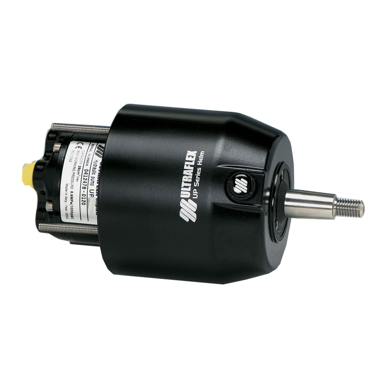
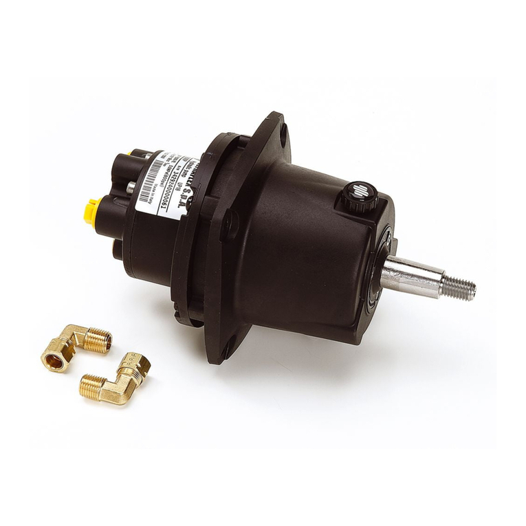
Ultraflex UFLEX SilverSteer UP25 F-SVS Manual

PUMPFORHYDRAULICSTEERING
SYSTEMS
InstallationandMaintenanceManual
(Dr./Dis./Des. n°25767/f08/05/2015) (REV.3)
UP25F-SVS
UP28F-SVS
UP33F-SVS
UP39F-SVS
UP25T-SVS
UP28T-SVS
UP33T-SVS
UP39T-SVS
PARTNER

UFLEXUSA
Sarasota,FL34243 -6442 ParklandDrive
DearCustomer,
Wewould liketothankyouforchoosingan ULTRAFLEX SpAproduct.
ULTRAFLEX SpAhas beenaleaderinsteeringsystemsforpleasureandprofessionalboatsformany
years.
All ULTRAFLEX SpAproductsaredesignedandmanufacturedtoensurethebestperformance.
To ensureyoursafetyandtomaintainahighqualitylevel, ULTRAFLEX SpAproductsareguaranteedonly
iftheyareusedwithoriginalspareparts(see attacheddocument"ApplicationSpareParts").
ULTRAFLEX SpAandQualityManagementSystemis certifiedCISQ-IQNetbytheItalianShippingRegistry
(RINA),inconformitywiththeUNIENISO9001:2008 rule. ULTRAFLEX SpAcertificationNo. 6669/02/S(former
420/96).
Thequalitymanagementsysteminvolvesallthecompanyresourcesandprocesses startingfromthe
design,inorderto:
- ensureproductqualitytothecustomer;
-maintainandimprovethequalitystandardsconstantly;
-pursueacontinuousprocess improvementtomeetthemarketneedsandtoincrease thecustomer
satisfaction;
-constantlytesttheproductstoverifytheirconformitywiththe2013/53/EU.
"Establishedin1989 UFLEX USAis aleaderinsteeringandcontrolsystemsforthemarineindustry.
Withfull manufacturingcapabilities inSarasota, Florida, UFLEX USAcansupportall sectorsofthemarine
industryregardless ofvolumeand/orproductrequirements. And,as anaffliateofthe ULTRAFLEX Group,
UFLEX USAhas tremendousresources todrawuponfornewproductdevelopmentinhydraulics, electronics
andmanyothertechnologies.
Innovativeproductdesignandunparalleleddedicationtoqualitycustomerserviceandproductsconti-
nuetobecornerstoneof UFLEX USA's growth.Todayourproductscanbefoundasoriginallyinstalled
equipmentonmanyofthemostwidelyknownandrespectedboatbrandsintheworld.
AftermarketpartscanbesourcedfromtrainedandexperienceddistributornetworktroughoutNorth
andSouthAmerica.
Ourdedicationtoprovidingthehighestqualityproductsandserviceis onlymatchedbyourcommitment
todevelopingnewproductsemployingthelastestmaterialsandtechnologytoenhanceourcustomer's
boatingexperience. Fromsteeringwheelstosophisticatedelectroniccontrols, UFLEX USAhas everything
youneedtomakesurethatyourboatlooksandperformit's bestformany,manyyears."

PUMP FORHYDRAULICSYSTEMS -page3 of27
ENGLISH
InstallationandMaintenanceManual
SECTION1-PRODUCTDESCRIPTION
1.1 HYDRAULICSTEERINGSYSTEMOPERATION...................................................................................................8
1.2 WARNINGSFOR THECORRECTPRODUCTUSE................................................................................................8
1.3 SYSTEMCONFIGURATIONS.................................................................................................................................8
1.4 PUMPDESCRIPTION..............................................................................................................................................9
1.5 PUMPTECHNICALFEATURES...........................................................................................................................10
TABLEOFCONTENTS
SECTION2-TRANSPORT
2.1 GENERALWARNINGS.........................................................................................................................................12
2.2 PACKAGINGCONTENTS......................................................................................................................................12
SECTION5-MAINTENANCE
5.1 ORDINARY MAINTENANCE.................................................................................................................................24
5.2 STEERINGWHEEL DISASSEMBLY....................................................................................................................24
5.3 TROUBLESHOOTING............................................................................................................................................24
SECTION3-INSTALLATION
3.1 NECESSARYTOOLSTO INSTALL PUMPSUP25F-SVS-UP28F-SVS-UP33F-SVS-UP39 F-SVS..........................14
3,2 PUMPUP25 F-SVS-UP28 F-SVS-UP33 F-SVS-UP39 F-SVSINSTALLATION......................................14
3.3 NECESSARYTOOLSTO INSTALL PUMPSUP25T-SVS-UP28T-SVS-UP33T-SVS-UP39 T-SVS..........................17
3,4 PUMPUP25 T-SVS-UP28 T-SVS-UP33 T-SVS-UP39 T-SVSINSTALLATION................................................17
3.5 TYPESOFINSTALLATION..................................................................................................................................20
3.6 HOSECONNECTIONTO THESYSTEM..............................................................................................................20
3.7 FILLINGANDPURGING.......................................................................................................................................21
3.7.1POSITIONINGOFTHEOILBOTTLE...................................................................................................................22
3.7.2PURGINGPROCEDURE.............................................................................................................22
3.8 GENERALRECOMMENDATION...........................................................................................................................22
SECTION6-DISMANTLING
6.1 DISMANTLING......................................................................................................................................................26
!
DOCUMENTREVISIONS....................................................................................................................................4
MANUALUSEANDSYMBOLSUSED................................................................................................................5
INTRODUCTION.................................................................................................................................6
WARRANTY..........................................................................................................................................................6
SECTION4-SAFETYWARNINGS
4.1 SAFETY WARNINGSDURINGUSEANDINSTALLATION...............................................................................23
4,2 CLOTHING..............................................................................................................................................................23

page4 of27-PUMP FORHYDRAULICSYSTEMS
ENGLISH
InstallationandMaintenanceManual
DOCUMENTREVISIONS
Rev. Date Revisiondescription
0
1
2
3
31/10/2008
08/03/2013
16/07/2014
15/12/2014
Firstedition
Additionofmodels39 F-SVS28-33-39 F-SVSandchange toswivelingfittings
Change tochapters "Packagingcontents"and"Oilbottlepositioning",
additionofmodel25 F-SVSand25 T-SVS
Change ofoilspecifications

PUMP FORHYDRAULICSYSTEMS -page5 of27
ENGLISH
InstallationandMaintenanceManual
Inthis manualthefollowingsymbolsareusedtoensuretheusersafetyandtoguarantee thecorrect
operationoftheproduct:
MANUALUSEANDSYMBOLSUSED
THEINSTALLATIONANDMAINTENANCE MANUALis thedocumentaccompanyingtheproductfromitssale
toitsreplacementanddischarge.Themanualis animportantpartoftheproductitself.
It is necessarytoreadcarefullythemanual,beforeANYACTIVITY involvingtheproduct,handlingand
unloadingincluded.
DANGER ImmediatehazardswhichCAUSEseverepersonalinjuryordeath.
WARNING
CAUTION
Thesymbolasideindicates all theoperationswhichmustbecarriedout
byqualifiedorskilledstaff,inordertoavoidhazards.
Werecommendtrainingthestaff inchargeoftheproductinstallation
andcheckingtheirknowledge.
NOTICE Importantinformationforthecorrectinstallationandformaintenance,that
doesnotcauseanydamage.
STERN
BOW
STARBOARD PORT
Thepictureasideexplainsthemeaningofsome
nauticalwordscontainedinthismanual.
LEGEND
m.p.h.=milesperhour
km/h=kilometresper
hour
10 m.p.h.=8,69 knots
10 m.p.h.=16,1km/h
10 knots =11,5m.p.h.
10 knots =18,5km/h
10 km/h=6,21 m.p.h.
10 km/h=5,4knots
Denotes thatahazard existswhichcanresult ininjuryordeathifproper
precautionsarenottaken.
Denotes areminderofsafetypracticesordirectsattentiontounsafe
practices whichcould result inpersonalinjuryordamagetothecraft or
componentsortotheenvironment.

page6 of27-PUMP FORHYDRAULICSYSTEMS
ENGLISH
InstallationandMaintenanceManual
WARRANTY
1. TwoYearLimited Warranty. UFLEX USA, Inc.warrantsthatallproductsmanufacturedby UFLEX USA,
Inc.or ULTRAFLEX S.p.A. andsold by UFLEX USAtotheretailpurchaser("Purchaser")thatfortwo(2)years
afterthedateofmanufacturetobefreefromdefectsduetomaterialorworkmanship,subjecttothe
exclusionsbelow.ImproperinstallationAVOIDSthis warranty.Installationshould onlybeattempetedby
atrainedandqualifiedtechnician.
2.Exclusions. Thislimitedwarrantydoesnotcoveranddoesnotextendtoanyofthefollowing:
(a) Failurecausedbynormalwearandtear,climaticconditions,misure,neglect,lackofproper
maintenance, accident,fireorothercasualtydamage, racing,overloading,negligence, modification,
beachingorgroundingofvessel,collision,impact,towing,actsofwarorhostilities;
(b) componentsnotmanufacturedby UFLEX USA, Inc., oritsaffiliates;
(c) costofremovalorreinstallationofanycomponent(includingcomponentsmanufacturedby UFLEX
USA,Inc.)ordisassemblyorreassemblyoftheunitcontainingthecomponent;
(d) componentsnotmanufacturedby UFLEX USA, Inc.or ULTRAFLEX S.p.A., whetherornotwarrantedby
theothermanufacturer;
(e) anyproductwhichhasnotbeenproperlyinstalled.
TECHNICALASSISTANCE SERVICE
INTRODUCTION
North-South-CentralAmerica:
UFLEX USA
6442 ParklandDrive
Sarasota, FL34243
Ph.:+1.941.351.2628
Fax: +1.941.360.9171
Email:uflex@uflexusa.com
www.uflexusa.com
UFLEX S.r.l.
ViaMiliteIgnoto,8A
16012 Busalla(GE)-Italy
Ph.:+39.010.962.01
Fax: +39.010.962.0333
Email:ut@uflexgroup.it
www.uflexgroup.it
This installationandmaintenancemanualrepresentsanimportantpartoftheproductandmustbeavailable
tothepeopleinchargeofitsuse andmaintenance.
Theusermustknowthecontentofthis manual.
UFLEX declinesallresponsibilityforpossiblemistakesinthismanualduetoprintingerrors.
Apartfromtheessentialfeaturesofthedescribedproduct, UFLEX reservestherighttomakethose
modifications, suchas descriptions, detailsandillustrations, thatareconsideredtobesuitableforits
improvement,orfordesignorsales requirements, atanymomentandwithoutbeingobligedtoupdatethis
publication.
ALL RIGHTSARERESERVED. Publishingrights, trademarks, partnumbers andphotographs of UFLEX products
containedinthismanualare UFLEX property.
Greatcarehas beentakenincollectingandcheckingthedocumentationcontainedinthismanualto
makeitas completeandcomprehensibleas possible. Nothingcontainedinthis manualcanbeinterpreted
as warrantyeitherexpressedorimplied-including,notinarestrictedway,thesuitabilitywarrantyforany
specialpurpose. Nothingcontainedinthis manualcanbeinterpretedas amodificationorconfirmationof
thetermsofanypurchase contract.
Toensurethecorrectproductandcomponentoperation,theproductmustbeinstalledbyqualifiedstaff.
Incase ofpartdamageormalfunction,please contactthequalifiedstaff orourTechnicalAssistanceService.
WARNING

PUMP FORHYDRAULICSYSTEMS -page7 of27
ENGLISH
InstallationandMaintenanceManual
3. Limitations. THEREPAIROR REPLACEMENTOFDEFECTIVE PARTSSHALL BEPURCHASER'SSOLE AND
EXCLUSIVE REMEDY AND UFLEX USA, INC,'SSOLE ANDEXCLUSIVE LIABILITY UNDERTHISWARRANTY.
LABOR FOR REPLACEMENTISNOT INCLUDED. UFLEX USA, Inc.'s obligationunderthis warrantyis limited
totherepairorreplacement(at UFLEX USA, Inc.'s soleelection)ofanycovereditemfoundtobedefective,
whendeliveredbyPurchaserpursuanttowrittenauthorizationandinstructionsfrom UFLEX USA, Inc.,
shippingprepaidto UFLEX USA, Inc.'s plantorotherdesignatedrepairfacility.Repairedorreplaced
itemsarewarrantedasprovidedhereinfortheunexpiredportionoftheapplicablewarrantyperiod.
THISWARRANTY, ANDTHERIGHTSANDREMEDIESUNDERIT, ISEXCLUSIVE ANDISGIVENINPLACE OF
ALLOTHERWARRANTIES,WHETHEREXPRESSOR IMPLIED, INCLUDINGANYIMPLIEDWARRANTYOF
MERCHANTABILITYOR FITNESS FOR PARTICULARPURPOSE,WHETHERARISINGBY LAW,CUSTOM,
CONDUCTOR USAGEOFTRADE,PURCHASER'SREMEDIESSHALL BELIMITEDASSTATEDHEREINAND
UFLEX USA, INC.SHALL NOT BELIABLE FOR ANYINCIDENTAL,CONSEQUENTIALOR INDIRECTDAMAGES
OR LOSSESRESULTINGFROMDEFECTS.THERETAILSELLERISNOT ACO-WARRANTOR ANDISNOT
AUTHORIZEDBY UFLEX USA, INC.TO AMENDOR MODIFYTHISLIMITEDWARRANTY INANYMANNER.
4.TransferabilityofWarranty. Thislimitedwarrantymaynotbetransferredtosubsequentpurchasers.
5.Miscellaneous. UFLEX USA,Inc.isanaffiliateof ULTRAFLEX S.p.A. UFLEX,USA,Inc., reservestherightto
makechanges inthedesignandconstructionofitsproductsatanytime, withoutnoticeandwithoutany
obligationtoincorporatesuchchanges intoproductsofpriormanufacture. This limitedwarrantyapplies
tonewcomponentssold by UFLEX USA, Inc.. This limitedwarrantycontainstheentireagreementsbetween
UFLEX USA,Inc.andPurchaserandsuspersedesallprioragreements,discussions,negotiations,
commitmentsandrepresentations,whetheroralorwritten,betweenthemregarding UFLEX USA,Inc's
warranty.If anyprovisionofthis limitedwarranty,ortheapplicationofit,is determinedtobeinvalidof
unenforceableforanyreason,theremainderofthislimitedwarrantyandtheapplicationofitshall not
beaffected.
6.Ultron3000 andPowerC. TheUltron3000 and"PowerC-UserandInstallationManual"describes
activities,operations, technicalspecificationswhichmustbefollowedduringtheinstallationand/or
usageoftheproduct,inordertokeepavalidwarranty.Descriptionsanddrawingsinthatmanualare
suitabletoallowinstallationanduseoftheproducttoskilledpersons.Incase ofdoubtand/orforany
information,pleasecontactourTechnicalService.
AllcommunicationsandnoticesfromPurchaserregardingthislimitedwarrantyshouldbesentto: UFLEX
USA, INC., 6442 ParklandDrive, Sarasota, FL34243; (941)351-2628.
Returnpolicy
Anyproductthatis presumeddefectiveshould bereportedto UFLEX USAwithin48hoursofreceiptor
discoveryinthefield.Uponnotification UFLEX USAwill attempttotroubleshoottheproblemwithourcustomer
overthephone. If weareunabletoresolvetheproblem UFLEX willissueaReturnGoodsAuthorization
numberandwerequirethattheproductinquestionbereturnedto UFLEX withallitspartsinitsoriginal
packaging.Theproductshouldbereturnedfreightprepaidto:
UFLEXUSA
RGA Department-RGA #
6442 ParklandDrive
Sarasota,Florida34243
Uponreceipt UFLEX will examinetheproducttodeterminethecause ofthedefect.If theproductis determined
tohaveadefectinworkmanshipormaterial,itwill berepairedatourdiscretion.
Ourwarrantydoes notcoverlabor,towingorotherexpenses. Further,itdoes notcoverproductsthathave
beenimproperlyinstalled,damagedininstallation,misapplied,ormisused.
Ourproductsarenotintendedforuseinracingapplications.

page8 of27-PUMP FORHYDRAULICSYSTEMS
ENGLISH
InstallationandMaintenanceManual
1.2Warningsforthecorrectproductuse
1PRODUCTDESCRIPTION
1.1Hydraulicsteeringsystemoperation
All UFLEX hydraulicsteeringsystems aredesignedinconformitywithUNI-EN-ISO 10592andA.B.Y.C.P21 regulations.
AllUFLEX steeringsystemscanoperateattemperaturesbetween-18°C(0°F)and+77°C(+170°F).Allthecomponents
aremadeforthemarineenvironment,usingmaterialsandworkingprocesseswhichofferlonglifeandsafety
underthemostextremeconditions.Ahydraulicsteeringsystemconsistsofasteeringpump,acylindertiedtothe
rudderortotheoutboard orsterndriveengineandtheconnectinghoses
(see picture).Undernormaloperatingconditions, aturnofthesteering
wheelwillpumptheoil,whichflowsinthroughthehosestothecylinder,
accordingtotheturndirection.Withtheconsequentcylindermovement
theoilwill flowtothepumpthroughthehosesandatthesametime
movestheengineorthehelmwhichareconnectedtothecylinder.The
pumpsUP25F-SVS,UP28 F-SVS,UP33F-SVS,UP39 F-SVS,UP25T-SVS,
UP28 T-SVS,UP33T-SVSandUP39T-SVSareequippedwithapressure
reliefvalve, whichpreventsoutgoingfluidfromreturningalongthesame
hose.Italso allowstheoperationofthesteeringsystemswithtwoor
moresteeringstations.Theunbalancedcylinderscannotbeusedwiththe
pumpsUP25F-SVS,UP28 F-SVS,UP33F-SVS,UP39 F-SVS,UP25T-SVS,
UP28T-SVS, UP33 T-SVSandUP39T-SVS.A wellbalancedsteeringsystem
needs acorrectchoiceofthepumpforthecylinder. UFLEX producesdifferent
pumpmodels, whichhavedifferentcapacity(cm3ofoilmovedeachsteeringwheelturn)andforeachtypeof
installation.Whilechoosingthepumpitis importanttoconsiderthecylindervolume.Thenumberofstarboardand
portturnsisdeterminedbytheratiobetweenthecylindervolumeandthepumpcapacity.Thereleasepressureof
thepressurereliefvalvesisof10,3MPa(105bar)(1500PSI).
Example:ifthepumphas acapacityof28cm3 [1,7cu.in.]andthecylinderhas avolumeof120 cm3 [7,3cu.in.],the
formulalookslikethis:120/28=4,2.Accordingly,thesteeringwheelwill turnabout4times beforethecylinderwill
completelyturnfromonesidetotheother.Incaseofinstallationswithdoublecylindersconnectedinparallelthe
cylindervolumemustbeadded.Applicationswithlessthan4turnsarenotrecommended,astheyneedahigher
effort,alsoapplicationswithmorethan8turnsarenotrecommended,as theresponse oftheboattosteeris slowly.
UFLEX steeringsystemsmustnotbeinstalledonraceboats.
All UFLEX steeringsystems mustnotbe installedonboats equippedwithengines whose maximumhorsepower
ishigherthanthehorsepowerratingapprovedbyboatmanufacturer.
Donotmodifythesteeringcylinderinanywaytofitittoyourapplication,otherwise thecylinderwillno
longeroperateinsafetyanditwill endangertheboatandtheoccupants.
WARNING
WARNING
DANGER
l
engine
cylinder
l
l
l
pump
ThepumpsUP25F-SVS,UP28F-SVS,UP33F-SVS,UP39 F-SVS,UP25T-SVS,UP28T-SVS,UP33 T-SVSandUP39
T-SVScannotbeusedwithunbalancedcylinders.
WARNING
1.3Systemconfigurations
ThepumpsUP25 F-SVS,UP28 F-SVS,UP33 F-SVS,UP39 F-SVS,UP25 T-SVS,UP28 T-SVS,UP33 T-SVSandUP39
T-SVScanonlybeusedwithSVShydrauliccylindersandhoses (outboard cylinderUC128-SVSandKitOB-SVS)
CAUTION
Alwaysconnectthehosescorrectlyasindicatedintheinstallationandmaintenancemanualsofthe
correspondinghydrauliccylinders.
WARNING
hydraulichoses

PUMP FORHYDRAULICSYSTEMS -page9 of27
ENGLISH
InstallationandMaintenanceManual
1.4Pumpdescription
ThepumpsUP25 F-SVS,UP28 F-SVS,UP33 F-SVSandUP39 F-SVShavebeendesignedandmanufactured
tobeusedas acomponentinthehydraulicsteeringsystems,as describedinthepreviousparagraph.
ThepumpsUP25 F-SVS,UP28 F-SVS,UP33 F-SVSandUP39 F-SVSmustbeinstalledonthefrontpartofthe
boatdashboard orsemi-built-inthroughflangeX64 orX57.
ThepumpsUP25 T-SVS,UP28 T-SVS,UP33 T-SVSandUP39 T-SVSmustbeassembledbymeansoftilt
X70(suppliedseparately).
Thefollowingpictures showthemainpumpcomponents:
PumpUP25 F-SVSorUP28 F-SVSorUP33 F-SVSorUP39
F-SVS
Ventfillerplug
Steeringwheelconnectionshaft
Connectionstothecylinder/s
1
2
3
UP25 F-SVSorUP28 F-SVSorUP33 F-SVSorUP39F-SVS
2
3
6
4
14
5
Connectionstotheadditionalstations
M6dowelsforfixingthepump tothedashboard
Pump UP25 T-SVSorUP28 T-SVSorUP33 T-SVSorUP39
T-SVS
Connectionshaft totiltX70
5
6
7
5
UP25 T-SVSorUP28 T-SVSorUP33 T-SVSorUP39 T-SVS
2
8
4
74
5
5
48

page10 of27-PUMP FORHYDRAULICSYSTEMS
ENGLISH
InstallationandMaintenanceManual
1.5Pumptechnicalfeatures
109 mm
[4,29 in.]
UP25 F-SVSorUP28 F-SVSorUP33 F-SVSorUP39 F-SVS
55 mm
[2,1in.]
85 mm
[3,34 in.]
Æ67 mm [2,6in.]
Æ67 mm [2,6in.]
Æ19 mm [0,75 in.]
Æ115 mm [4,53 in.]
M12
Æ77 mm [3,03 in.]
Therelease pressureofthepressurereliefvalves does notcorrespondtothesystemnormalpressurebut
itrepresentsonlytheuse limits.
CAUTION
194 mm [7,64 in.]
Thereliefvalvepressureis nottheoneexpectedundernormalconditionsofthesystem:itis thepressure
setunderextremeworkingconditions.
CAUTION
SPECIFICATIONS
PUMPUP25F-SVS
PUMPUP28F-SVS
PUMPUP33F-SVS
PUMPUP39F-SVS
Capacity 25cc/rev. -1,7cu.in/rev.28cc/rev.- 1,7cu.in/rev.33 cc/rev. - 2,0cu.in/rev.39cc/rev.- 2,0cu.in/rev.
Pressurerelief valve
releasepressure 105 bar(1500 psi) 105bar (1500psi) 105 bar(1500 psi) 105bar (1500psi)
No.of pistons 5 5 7 7
Max.steeringwheel
diameter 710 mm (28 in.) 710mm (28in.) 710mm (28in.) 710mm (28in.)
Max.steeringwheel
height 152mm (6in.) 152mm (6in.) 152 mm (6in.) 152mm(6in.)
Weight 5kg(11lbs) 5 kg (11lbs) 5kg(11lbs) 5 kg(11lbs)
Oil OIL15 OIL15 OIL15 OIL15
SPECIFICATIONS
PUMPUP25T-SVS
PUMPUP28T-SVS
PUMPUP33T-SVS
PUMPUP39T-SVS
Capacity 25 cc/rev. -1,7 cu.in/rev.28cc/rev.- 1,7cu.in/rev.33 cc/rev. - 2,0 cu.in/rev.39cc/rev.- 2,0cu.in/rev.
Pressurerelief valve
releasepressure 105 bar(1500 psi) 105bar (1500psi) 105 bar(1500 psi) 105 bar (1500 psi)
No.of pistons 5 5 7 7
Max.steering wheel
diameter 406 mm (16 in.) 406 mm (16 in.) 406mm (16in.) 406 mm (16 in.)
Max.steering wheel
height 152 mm (6in.) 152mm (6 in.) 152 mm (6 in.) 152mm (6 in.)
Weight 5kg (11 lbs) 5 kg (11lbs) 5kg (11 lbs) 5 kg(11lbs)
Oil OIL 15 OIL15 OIL 15 OIL 15

PUMP FORHYDRAULICSYSTEMS -page11 of27
ENGLISH
InstallationandMaintenanceManual
The pumpsUP25 T-SVS,UP28 T-SVS,UP33 T-SVSe UP39 T-SVScanonlybeusedwithtilt UFLEX X70 (supplied
separately).
.
UP25 T-SVSorUP28 T-SVSorUP33 T-SVSorUP39 T-SVS
CAUTION
174 mm [6,85 in.]
Æ127 mm[5in.]
196 mm [7,7in.]
6°
Æ115 mm[4,5in.]
Æ76 mm[3in.]

page12 of27-PUMP FORHYDRAULICSYSTEMS
ENGLISH
InstallationandMaintenanceManual
2.1Generalwarnings
2TRANSPORT
ThepumpUP25F-SVS,UP28 F-SVS,UP33F-SVS,UP39 F-SVS,UP28 T-SVS,UP33T-SVSandUP39 T-SVSweight
withtheirpackagingis 5kg (11 pounds)andso theycanbehandledmanually.
2.2Packagingcontents
Beforeusingtheequipmentcheckthattheproducthasnotbeendamagedduringtransport.
Also makesurethatallthestandardcomponentsareinthepackaging(see list).Incase ofdamage,
notifytheclaimtotheforwarderandinformthesupplier.
WARNING
Thestaff inchargeofhandlingmustoperatewithprotectivegloves andsafetyshoes.
UP25 F-SVSoUP28 F-SVSoUP33 F-SVSoUP39 F-SVS
THESTANDARD PACKAGINGCONTAINS:
A)No. 1pumpUP25 F-SVSorUP28 F-SVSorUP33 F-SVSorUP39 F-SVS.
B)No. 290°swingingunionstoconnectthehoses;
No. 4nutsforfixingthepumptothedashboard;
No. 4washersforfixingthepumptothedashboard;
No. 1nutforsteeringwheeltightening;
No.1washerforsteeringwheeltightening;
No. 1keyforsteeringwheeltightening
No. 1labelforplug.
The packagingmustbe disposed ofaccording to theexisting laws.
CAUTION
l
l
A
B

PUMP FORHYDRAULICSYSTEMS -page13 of27
ENGLISH
InstallationandMaintenanceManual
B
A
UP25 T-SVSorUP28 T-SVSorUP33 T-SVSorUP39 T-SVS
THESTANDARD PACKAGINGCONTAINS:
A)No. 1pumpUP25 T-SVSorUP28 T-SVSorUP33 T-SVSorUP39 T-SVS.
B)No. 290°swingingunionstoconnecttheKitOB hoses (suppliedseparately);
No. 1labelforplug.
l
l
The packagingmustbe disposed ofaccording to theexisting laws.
CAUTION

page14 of27-PUMP FORHYDRAULICSYSTEMS
ENGLISH
InstallationandMaintenanceManual
3.2PumpUP25F-SVS-UP28F-SVS-UP33F-SVS-UP39F-SVSinstallation
1Selectasuitableplaceforthesteeringstation.
Makesurethatthereis enoughmanoeuveringspace
forthesteeringwheelandforthesteeringpumpand
itspipes andfittings.
Inordertofixthepumpproperly,themaximum
dashboard thickness mustbe30 mm [1,18 in.].
Differentthicknesses could compromise thedriving
safety.
Makesurethatthebreakingringofthe4self-locking
nutssuppliedis engagedbythedowelthread.
WARNING
3INSTALLATION
3.1Necessary toolstoinstall pumpsUP25F-SVS-UP28F-SVS-UP33 F-SVS-UP39
F-SVS
Loctite542/545
(onlyforadditional
station)
Torque
wrench
Drill Openend
wrench
10 mm
Openend
wrench
19 mm
2Removetheplugs(1)fromthepump(2)byusinga
screwdriver.
7/16"openend
wrench
(onlyfor
additional
station)
MOLYKOTE® 1000
Screwdriver 4mm Allen
wrench
(onlyfor
additional
station)
Openend
wrench
11/16"
1
2
1
min.95 mm [3.74 in.]
spessoremax.
cruscotto30 mm[1,18 in.]

PUMP FORHYDRAULICSYSTEMS -page15 of27
ENGLISH
InstallationandMaintenanceManual
5Byusingthepropertemplatesuppliedwith
this manual,maketheholes forthedowels(5)
requiredbytheinstallationinthesuitable
positiononthedashboard.
5
3Screwthenutscompletelyonthecorresponding
90°unions(3),Fitandscrewtheunionsmanuallyas
indicatedinthepictureuntiltheyareinserted
completely.Turnthemuntiltheyarepositioned
correctlywithrespectto thepipes byunscrewingthem
nomorethanonerevolution,thentightenthenuts
witha11/16"Allenwrenchwithatorqueof17,6Nm
(13 lb ft) untilthewashertouches thenut.
DO NOT USEteflontapeoradhesivetape.
DONOTPUTanythreadsealantlikeLoctite542or
similarproducts.
WARNING
System fitting
Connectionfor
additional
station*
3
3
Connectionforadditional
station*
System fitting
*exceptforpumps
series"NV"
4FITTINGAPPLICATIONFOR ADDITIONALSTATIONS
Position3/8"straightunions(4)onthepumpsas
indicatedinthepicture.
PutsomefittingsealanttypeLoctite542 orLoctite545
onthethread.Fitandscrewmanuallythefittings(4)
untiltheyarecompletelyinserted;thentightenthem
witha7/16"openendwrenchwithatorqueof17.6
Nm(156 lb ft).
Connectionforadditional station
System fitting
Do notuseteflontapeoradhesivetape. Payattention
tothesealantpositioning:ifitis insertedintothe
system,itcould blockitandmakeitunusable.
WARNING
4
Connectionforadditional
station
System fitting
ONLYINCASEOFADDITIONALSTATIONS

page16 of27-PUMP FORHYDRAULICSYSTEMS
ENGLISH
InstallationandMaintenanceManual
6Positionthepump(2)onthedashboard front
side(6)interposingthegasket(7)andfix itby
insertingthe4washers(8)andbytightening
the4self-lockingnuts(9)witha10 mm wrench
andatorqueof10 Nm(7,4 lbft).
WARNING
Installthepumpbypositioningthefillinghole
(10)towards thetop(see the picture)fortheright
pumpoperationandtoallowfillingandpurging
thesystemcompletely(see par.3.7).
7Positionthesteeringwheelsupplied
separately(11)onthepumpshaft(12)byusing
thesuitablekey(13).Insertthewasher(14)and
tightentheself-lockingnut(15)witha19mm open
endwrenchandwitha torqueof40 Nm(29,5 lbft);
thengrease thethreadbyusingsomeanti-seize
grease MOLYKOTE® 1000 orasimilarone.
If theself-lockingnuts aredisassembled(9),they
mustbereplaced.(Contactourassistance
service,seepage6).
CAUTION
If theself-lockingnut(15)is disassembled,itmust
bereplaced.(Contactourassistanceservice, see
page6).
CAUTION
2
8
9
6
10
12
11
14
15
13
7
8
99
8
8
9

PUMP FORHYDRAULICSYSTEMS -page17 of27
ENGLISH
InstallationandMaintenanceManual
3.4PumpUP25T-SVS-UP28T-SVS-UP33T-SVS-UP39T-SVSinstallation
1Selectasuitableplaceforthesteering
station.Makesurethatthereisenough
manoeuveringspaceforthesteeringwheeland
forthesteeringpumpanditspipes andfittings.
12°
12°
12°
12°
min.260 mm [10,24 in.]
3.3Necessarytoolstoinstall pumpsUP25T-SVS-UP28T-SVS-UP33 T- SVS-
UP39T-SVS
Openendwrench
11/16"
*Thetoolsto
assembletiltX70
arelistedinthe
manualenclosed
totilt X70.
Screwdriver
Thetilt X70 mechanismis suppliedseparately.
CAUTION
4
3Fix thebracket(3)suppliedwithtilt X70 tothe
dashboard (4)byfollowingtheinstructions
enclosedtotiltX70.
3
2Removetheplugs(1)fromthepump(2)by
usingascrewdriver.
2
1
1
Loctite542/545 (onlyfor
additionalstation)
7/16"openendwrench
(onlyforadditionalstation)

page18 of27-PUMP FORHYDRAULICSYSTEMS
ENGLISH
InstallationandMaintenanceManual
4Screwthenutscompletelyonthecorresponding
90°unions(3),Fitandscrewtheunionsmanuallyas
indicatedinthepictureuntiltheyareinserted
completely.Turnthemuntiltheyarepositioned
correctlywithrespectto thepipes byunscrewingthem
nomorethanonerevolution,thentightenthenuts
witha11/16"Allenwrenchwithatorqueof17,6Nm
(13 lb ft) untilthewashertouches thenut.
DO NOT USEteflontapeoradhesivetape.
DONOTPUTanythreadsealantlikeLoctite542or
similarproducts.
WARNING
6Fix thepumptothebracket(3)suppliedwith
tiltX70byusingthe3M8screws(7)supplied
withtilt X70 accordingtotheinstructionsenclosed
totilt X70.
3
WARNING
Installthepumpbypositioningthefillinghole
(8)towardsthetop(see thepicture)fortheright
pumpoperationandtoallowfillingandpurging
thesystemcompletely(see par.3.7).
7
8
System fitting
Connectionfor
additionalstation
5
5
Connectionforadditional
station
System fitting
5FITTINGAPPLICATIONFOR ADDITIONALSTATIONS
Position3/8"straightunions(6)onthepumpsas
indicatedinthepicture.
PutsomefittingsealanttypeLoctite542 orLoctite545
onthethread.Fitandscrewmanuallythefittings(6)
untiltheyarecompletelyinserted;thentightenthem
witha7/16"openendwrenchwithatorqueof17.6
Nm(156 lb ft).
Connectionforadditional station
System fitting
Do notuseteflontapeoradhesivetape. Payattention
tothesealantpositioning:ifitis insertedintothe
system,itcould blockitandmakeitunusable.
WARNING
6
Connectionforadditional
station
System fitting
ONLYINCASEOFADDITIONALSTATIONS

PUMP FORHYDRAULICSYSTEMS -page19 of27
ENGLISH
InstallationandMaintenanceManual
7Alignandinsertthetilt universaljointinto
thepumpshaft bylooseningabout1-1.5turns
thescrews(9)ontheuniversaljointitself always
accordingtotheproceduredescribedinthe
installationmanualsuppliedwithtilt X70.
Retightenthescrews(8)andfix thetilt.
9
9
NOTICE
Thekit UFLEX suppliedseparately(see thecorrespondinginstructions)canbeusedonpumpsUP28F-SVS,
UP33F-SVS,UP39F-SVS,UP28T-SVS,UP33T-SVSandUP39 T-SVStosimplifythehydraulicsystemfillingand
purging.

page20 of27-PUMP FORHYDRAULICSYSTEMS
ENGLISH
InstallationandMaintenanceManual
3.6 Hoseconnectiontothesystem
1Connectthehydraulichoses UFLEX kitOB-SVS(suppliedseparately)joiningthepumpandthecylinder
byfollowingtheinstructionsgivenintheinstallationmanualofthekitOB-SVS.
2Ifoneormoreadditionalsteeringstationsareinstalled,use thekitOB-2Sbyfollowingthesuitable
instructions.
CAUTION
Connecthoses as shownintheinstallationandmaintenancemanualofthehydrauliccylinderforoutboard
enginesUC128-SVS.
3.5Typesofinstallation
ThepumpsUP25F-SVS,UP28 F-SVS,UP33 F-SVS,UP39 F-SVS,UP28 T-SVS,UP33 T-SVSandUP39T-SVScanbe
installedinasingleordualstationandtheycanbeusedonlywithSVShydrauliccylindersandhoses
(outboard cylinderUC128-SVSandKitOB-SVS).
MAINSTEERINGSTATION ADDITIONALSTEERINGSTATION
1
2
4
1.mainsteeringstation
2.additionalsteeringstation
3.kitOB-SVS
4.3/8"pipeincludedkitOB-2S
5.ventplug(blackplug)
6.plugwithoutvent(greyplug)
5
6
3
3
3
3
NOTICE
KitOB-2Sis suppliedseparatelyincase
ofapplicationswithdoublestation.
KitOB-SVS
cylinder
connecting
pipe
KitOB-SVS
cylinder
connecting
pipe
KitOB-2S KitOB-SVS
cylinder
connecting
pipe
KitOB-SVS
cylinder
connecting
pipe
KitOB-2S
This manual suits for next models
7
Table of contents
Other Ultraflex Water Pump manuals
Popular Water Pump manuals by other brands

Grundfos
Grundfos CREC Installation and operating instructions

Golander pump
Golander pump BT-F NEW Operation manual

PSG
PSG Wilden PS Stallion Series Engineering, operation & maintenance

Simpson
Simpson SSTP02 use and care manual

Becker
Becker Variair VASF 2.80/2-0.AC230 operating instructions

Edwards
Edwards RV3 instruction manual