Preface:
9650 & 9651 – Ultra-Hard Top P8 Plus
This unit comes as one 4 Drum unit with one Extender Kit.
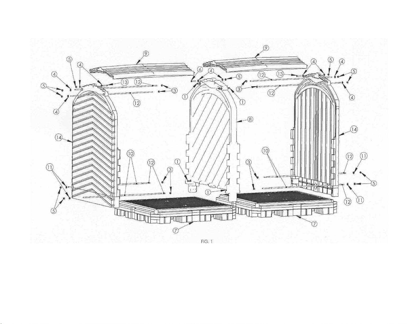
•Please refer to the Figure 1 & 2 and parts list on Pages 4-6.
9652 & 9653 – Ultra-Hard Top P12 Plus
This unit comes as two 4 Drum units and one Extender Kit
Each 4 drum unit will consist of one End Wall and one Interior wall
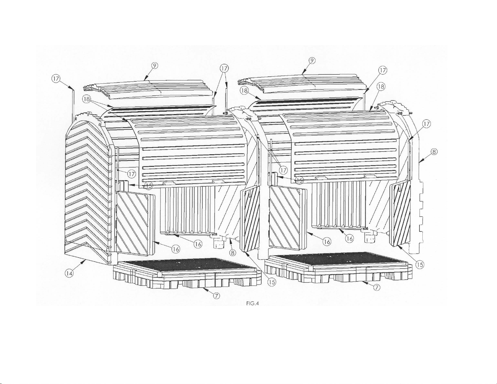
•Please refer to Figures 3,4,5 & 6 and parts list on pages 7-12.
•Follow the assembly instructions starting with Step 13 on page 21 when
adding the End Wall unit to complete the assembly.
9654 & 9655 – Ultra-Hard Top P16 Plus
This unit comes as two 4 Drum units and two Extender Kits
Each 4 drum unit will consist of one End Wall and one Interior wall
•Please refer to Figures 3,4,5 & 6 and parts list on pages 7-12.
•Follow the assembly instructions starting with Step 13 on page 21 when
adding the End Wall unit to complete the assembly.
9656 & 9657 – Ultra-Hard Top P20 Plus
This unit comes as three 4 Drum units and two Extender Kits
Two 4 drum unit will consist of one End Wall and one Interior wall and one 4 drum unit
will consist of two interior walls
•Please refer to Figures 3,4,5 & 6 and parts list on pages 7-12.
•Follow the assembly instructions starting with Step 13 on page 21 when
adding the End Wall unit to complete the assembly.
9658 & 9659 – 4-Drum Hard Top Extension Kit
This unit comes unassembled.
It is used to add on to any 8,12,16,20, etc… existing assembly.
•Please refer to the Figure 7 & 8 and parts list on Pages 13-15.
•Follow the assembly instructions starting with
1) Step 1 on page 16 if assembling an Add-on Roll Top Hardcover to an
existing unit that has already been fully assembled.
*Note: Requires some disassembling first to add on.
2) Step 5 on page 17 if adding an Add on Roll Top Hardcover to a unit
that has an interior wall exposed.