manuals.online logo
Brands
  1. Home
  2. •
  3. Brands
  4. •
  5. UMT
  6. •
  7. Microphone System
  8. •
  9. UMT MICPRO UHF-5100 User manual

UMT MICPRO UHF-5100 User manual

UHF PLL MULTI CHANNELS
WIRELESS MICROPHONE SYSTEM
USER'S MANUAL
PLEASE READ THIS MANUAL CAREFULLY BEFORE OPERATION
UMT
MICPRO UHF-5100
1. Microcomputer controlled PLL synthesized oscillation circuit.
2. UHF high band with multi selectable frequencies.
3. Automatic frequency selection and automatic transmitter setup.
4. Adopt high sensitivity and wide frequency response dynamic capsule
to reproduce original sound.
5. Advanced compression circuit to avoid noise.
6. LCD display for easy operation.
7. Operating range is more than 100M in line and sight area.
-1-
Thank you for choosing our UHF PLL multi channels wireless
microphone system. Your new system is rugged, reliable, easy to set up
and operate, and produces outstanding audio clarity. Whether you're a
vocalist, guitarist or instrumentalist, this wireless system will show you
how easy wireless can be, and how good wireless can sound. This user
guide included with your system will tell you all you need to know to get
your system working right away.
1. Receiver
2. AC/DC adapter
3. 6.35mm cable
4. 1/4 Wave Antennas
5. Transmitter
6. AA batteries
7. User guide
INTRODUCTION
FEATURES
PACKAGE CONTENTS
1 PC
1 PC
1 PC
2 PCS
1 PC
2 PCS
1 PC
-6-
RECEIVER
Frequency: fixed permitted
Frequency Stability:10ppm
Sensitivity: 13dBuV
Adjacent channel rejection:75dB
Image rejection: 95dB
Audio Output:200MV
Output Impedance: XLR connector: 200 ; 1 / 4 inch connector: 1k
S/N ratio: 100dB
0.1%
Frequency response: 50Hz-15KHz
:100m( in line and sight area)
Power supply: DC12V--18V
Housing: Metal
TRANSMITTER
Frequency: fixed permitted
Frequency Stability: 10ppm
Transmitting power: <10mW
Spurious emission: >65dB
Modulation: FM
Max modulation: 75K
Power supply: 3V (2 AA batteries)
Current consumption: 120mA
Total Harmonic Distortion: <
Operating Range
SPECIFICATIONS
-2-
RECEIVER PARTS DESCRIPTION
1 2 345 6 788
9 10 11 12
Front
Rear
SQUELCH
1.
2. Infrared (IR) port: Broadcasts IR signal to transmitter to synchronize
frequencies.
3. LCD display: display group, channel no, RF and AF level.
4. Select switch: Press to select the currently displayed menu option.
5. Menu switch: Press to scroll through menu options.
6. Sync Button: Press to initiate IR connection between receiver and
transmitter.
7. Volume control: Turn to adjust volume.
8. Antenna connector: To install supplied antenna here.
9. Squelch adjust
10. Individual Balanced XLR output
11. Mixed 1 / 4 " output jack
12. MIC/LINE switch
13. DC input jack
On/Off switch: Turn on/off the receiver.
13
-5-
Any option displayed on screen will generally "time out" after five seconds.
Group Selection
Channel Selection
2x
3x
1. Press MENU twice. LCD screen will display Group Select.
2. Then press SELECT repeatedly to increase the group number.
3. When the correct group is displayed, either wait five seconds for
the screen to time out, or press SYNC button to escape.
1. Press MENU three times. LCD screen will display Channel Select.
2. Then press SELECT repeatedly to increase the channel number.
3. When the correct channel is displayed, either wait five seconds for
the screen to time out, or press SYNC button to escape.
MANUAL SELECTION OF GROUP/CHANNEL
We suggest to use Auto Channel Select to select the best channels.
1. Press and hold the SELECT button until the GROUP and CHANNEL
displays begin to alternate.
2. To change the group setting, release the SELECT button while
GROUP is displayed. While GROUP is flashing, pressing SELECT
button repeatedly to increase the group setting.
3. To change the channel setting, release the SELECT button while
CHANNEL is displayed. While CHANNEL is flashing, pressing
SELECT button to increase the channel setting.
MANUAL SELECTION OF RECEIVER GROUP/CHANNEL
MANUAL SELECTION OF TRANSMITTER GROUP/CHANNEL
-3-
1. Interchangeable microphone head
2. Power / Infrared(IR) /Mute indicator:
Green-ready; Orange-mute on;
Flashing orange-IR transmission in
process
3. LCD screen: display group, channel
number and battery power.
4. On-off / mute switch: Press and hold
1~2 seconds to turn microphone on
or off. Press shortly to mute/unmute.
5. Select switch: To set up transmitter
channel manually.
6. Battery cover/compartment
7. IR port: Receives infrared beam from
receiver to synchronize frequencies.
HANDHELD MICROPHONE PARTS DESCRIPTION
1. Antenna
2. LCD screen: display channel
number and battery power.
3. Select switch: to set up
transmitter channel manually.
4. IR port: Receives infrared beam
from receiver to synchronize
frequencies.
5. Battery cover/compartment
6. Power / IR / Mute indicator:
Green-ready; Orange-mute on;
Flashing orange-IR transmission
in process
7. On-off / mute switch: Press and
hold 1~2 seconds to turn on/off
transmitter. Press shortly to
mute/unmute.
8. 3-Pin Microphone Input Jack
9. Belt clip
BODY PACK TRANSMITTER PARTS DESCRIPTION
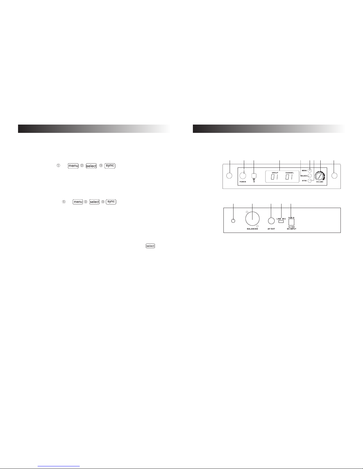
SYSTEM SETUP
Note: Transmitting devices such as cellular phones and two-way radios
may interfere with wireless audio transmissions. Keep your transmitters
and receivers away from these and other potential sources of
interference.
Receiver Automatic Frequency Selection
1. Turn on the receiver.
2. Press MENU once and then SELECT. Receiver will start searching
for a clear channel automatically.
Automatic Transmitter Setup
1. After receiver channel is set, turn on the transmitter.
2. Open the transmitter battery compartment to expose the IR port.
3. With the IR port pointed to the receiver, press SYNC on receiver.
4. Transmitter power indicator will flash orange. When the indicator stops
flashing and light green, and receiver RF indicator will light green, the
transmitter is SYNC to the receiver.
5. Close the transmitter battery compartment.
When using multiple systems in a single installation, repeat above steps
to set up each system.
Be sure that only one transmitter IR port is exposed when
synchronizing a system.
MULTIPLE SYSTEM SETUP
SINGLE SYSTEM SETUP
When you set 2nd system receiver channel please keep 1st system
transmitter on.
-4-

Popular Microphone System manuals by other brands

Alto MOD-800R owner's manual

Alto

Alto MOD-800R owner's manual

Polsen ULW-96 product manual

Polsen

Polsen ULW-96 product manual

Fiber-Span AC3101-BTR-4 Installation guide and user's manual

Fiber-Span

Fiber-Span AC3101-BTR-4 Installation guide and user's manual

Okayo EJ-501IR user guide

Okayo

Okayo EJ-501IR user guide

Zeck Audio Daisy VHF owner's manual

Zeck Audio

Zeck Audio Daisy VHF owner's manual

MED Associates ANL-940-1 user manual

MED Associates

MED Associates ANL-940-1 user manual

ADC Digivance ICS 800 installation instructions

ADC

ADC Digivance ICS 800 installation instructions

Auburn Gear Power Wheel Model 6 Service manual

Auburn Gear

Auburn Gear Power Wheel Model 6 Service manual

Sennheiser EW 100 G2 Instructions for use

Sennheiser

Sennheiser EW 100 G2 Instructions for use

Azden Body-pack Transmitter 35BT user guide

Azden

Azden Body-pack Transmitter 35BT user guide

TriSquare DVM-900 operating instructions

TriSquare

TriSquare DVM-900 operating instructions

Vitek VT-3835 Manual instruction

Vitek

Vitek VT-3835 Manual instruction

Sennheiser CHG 2 quick guide

Sennheiser

Sennheiser CHG 2 quick guide

Phonic WM Series user manual

Phonic

Phonic WM Series user manual

Eikon J&M user manual

Eikon

Eikon J&M user manual

AKG WMS 400 Short form service manual

AKG

AKG WMS 400 Short form service manual

Velleman MICW41 user manual

Velleman

Velleman MICW41 user manual

Azden 105UPR user guide

Azden

Azden 105UPR user guide

manuals.online logo
manuals.online logoBrands
  • About & Mission
  • Contact us
  • Privacy Policy
  • Terms and Conditions

Copyright 2025 Manuals.Online. All Rights Reserved.