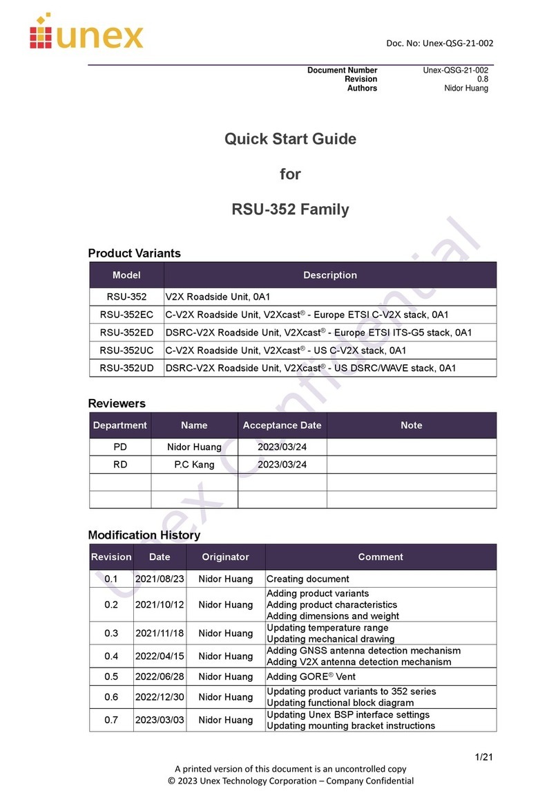
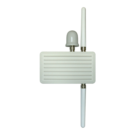
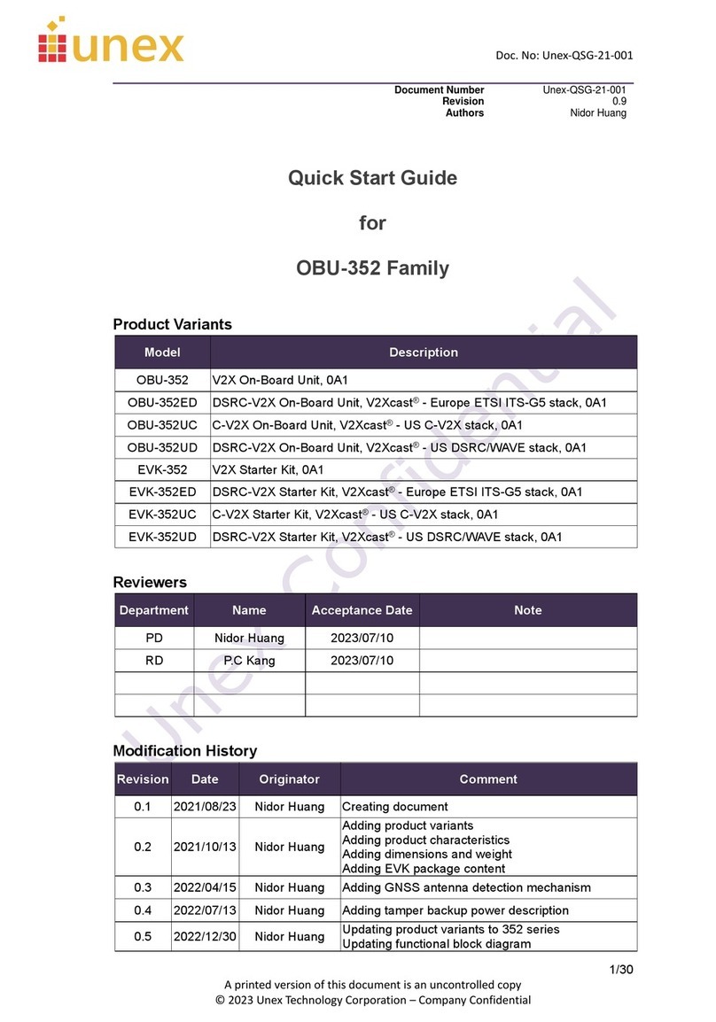
Unex OBU-300 User manual

Doc. No: Unex-QSG-21-001
1/27
A printed version of this document is an uncontrolled copy
© 2021 Unex Technology Corporation – Company Confidential
Document Number
Unex-QSG-21-001
Revision
0.2
Authors
Nidor Huang
Quick Start Guide
for
OBU-300 Family
Product Variants
Model
Description
OBU-301E(v2)
V2X On-Board Unit, V2Xcast® - ITS-G5 stack, 0A1/0A2
OBU-301U(v2)
V2X On-Board Unit, V2Xcast® - WAVE stack, 0A1/0A2
OBU-351
V2X On-Board Unit, 0A1/0A2
OBU-351E
V2X On-Board Unit, V2Xcast® - C-V2X stack, Europe, 0A1/0A2
OBU-351U
V2X On-Board Unit, V2Xcast® - C-V2X stack, USA, 0A1/0A2
EVK-351
V2X Starter Kit, 0A1/0A2
EVK-351E
V2X Starter Kit, V2Xcast® - C-V2X stack, Europe, 0A1/0A2
EVK-351U
V2X Starter Kit, V2Xcast® - C-V2X stack, USA, 0A1/0A2
Reviewers
Department
Name
Acceptance Date
Note
PD
Nidor Huang
2021/10/13
RD
JY Ou
2021/10/13
Modification History
Revision
Date
Originator
Comment
0.1
2021/08/23
Nidor Huang
Creating document
0.2
2021/10/13
Nidor Huang
Adding product variants
Adding product characteristics
Adding dimensions and weight
Adding EVK package content

Doc. No: Unex-QSG-21-001
2/27
A printed version of this document is an uncontrolled copy
© 2021 Unex Technology Corporation – Company Confidential
TABLE OF CONTENTS
1. Objective...................................................................................................5
2. Reference .................................................................................................5
3. Limited Warranty Policy ............................................................................5
4. Safety Guidelines......................................................................................6
5. Product Appearance .................................................................................6
6. Functional Block Diagram.........................................................................8
7. Electrical Characteristics ..........................................................................9
7.1. Absolute Maximum Ratings .................................................................................. 9
7.2. Recommended Operating Conditions ................................................................... 9
7.3. Power Consumption.............................................................................................11
8. I/O Interfaces ..........................................................................................11
8.1. OBU-301(v2)/OBU-351 ........................................................................................11
8.1.1. External Interfaces .................................................................................11
8.1.2. Internal Interfaces ................................................................................. 15
8.2. I/O Conversion Board (EVK-351 Series Only) .................................................... 20
8.2.1. Console................................................................................................. 21
8.2.2. Ext GNSS.............................................................................................. 21
8.2.3. CAN0 .................................................................................................... 22
8.2.4. CAN1 .................................................................................................... 23
8.2.5. USB1..................................................................................................... 24
8.2.6. GPIO ..................................................................................................... 24
8.2.7. DC Power Jack ..................................................................................... 25
8.2.8. Reset Button ......................................................................................... 25
9. Dimensions and Weight ..........................................................................26
10. Software Settings....................................................................................27
LIST OF FIGURES
Figure 1: OBU-301(v2)/OBU-351 series package content ........................................................ 7
Figure 2: EVK-301(v2)/EVK-351 series package content ......................................................... 7
Figure 3: OBU-301(v2)/OBU-351 series complete assembly appearance ............................... 8
Figure 4: Functional block diagram ........................................................................................... 8
Figure 5: LED............................................................................................................................11
Figure 6: USB0 (CN2) ............................................................................................................. 12
Figure 7: Ethernet port............................................................................................................. 13
Figure 8: I/O port (J8) .............................................................................................................. 13
Figure 9: I/O port cable connector ........................................................................................... 14

Doc. No: Unex-QSG-21-001
3/27
A printed version of this document is an uncontrolled copy
© 2021 Unex Technology Corporation – Company Confidential
Figure 10: V2X antenna ports.................................................................................................. 15
Figure 11: GNSS antenna port ................................................................................................ 15
Figure 12: Mini PCIe Port (J6) ................................................................................................. 16
Figure 13: SIM slot (J7) ........................................................................................................... 17
Figure 14: Tamper input (J5) ................................................................................................... 18
Figure 15: SAR ADC input (J4)................................................................................................ 19
Figure 16: DIP switches. SW3 (Left), SW2 (Right).................................................................. 20
Figure 17: EX-46 (Left), EX-47 (Right) .................................................................................... 21
Figure 18: Console port (CN4) ................................................................................................ 21
Figure 19: Ext GNSS port (CN6) ............................................................................................. 21
Figure 20: CAN0 port (CN5) .................................................................................................... 22
Figure 21: CAN0 terminator jumpers (JP1/JP2)...................................................................... 23
Figure 22: CAN1 port (CN7) .................................................................................................... 23
Figure 23: CAN1 terminator jumpers (JP3/JP4)...................................................................... 23
Figure 24: USB1 port (CN2) .................................................................................................... 24
Figure 25: GPIO headers (J1) ................................................................................................. 24
Figure 26: DC power jack ........................................................................................................ 25
Figure 27: Reset button ........................................................................................................... 25
Figure 28: Mechanical dimensions - TOP ............................................................................... 26
Figure 29: Mechanical dimensions - FRONT .......................................................................... 26
LIST OF TABLES
Table 1. Absolute maximum ratings........................................................................................... 9
Table 2. Recommended operating conditions ........................................................................... 9
Table 3: Power consumption ....................................................................................................11
Table 4: LED function .............................................................................................................. 12
Table 5: USB0 (CN2) pinout .................................................................................................... 12
Table 6: Ethernet LED function................................................................................................ 13
Table 7: I/O port pin map (J8) .................................................................................................. 14
Table 8: I/O port pinout (J8) ..................................................................................................... 14
Table 9: Mini PCIe pinout (J6, Row 0) ..................................................................................... 16
Table 10: Mini PCIe pinout (J6, Row 1) ................................................................................... 16
Table 11: Tamper functions (J5)............................................................................................... 18
Table 12: SAR ADC functions.................................................................................................. 19
Table 13: SAR ADC performance ............................................................................................ 19
Table 14: SW2 and SW3 functions .......................................................................................... 20
Table 15: Console pinout (CN4) .............................................................................................. 21
Table 16: Ext GNSS pinout (CN6) ........................................................................................... 22

Doc. No: Unex-QSG-21-001
4/27
A printed version of this document is an uncontrolled copy
© 2021 Unex Technology Corporation – Company Confidential
Table 17: CAN0 pinout (CN5) .................................................................................................. 22
Table 18: CAN1 pinout (CN7) .................................................................................................. 23
Table 19: USB1 pinout (CN2) .................................................................................................. 24
Table 20: GPIO pinout (J1) ...................................................................................................... 24
Table 21: Dimensions and weight............................................................................................ 26
Table 22: Unex BSP interface settings .................................................................................... 27

Doc. No: Unex-QSG-21-001
5/27
A printed version of this document is an uncontrolled copy
© 2021 Unex Technology Corporation – Company Confidential
1. Objective
The purpose of this document is to provide necessary information to help setup and
installation of OBU-301(v2)/OBU-351 series product. To provide for safe installation and
operation of the equipment, read the safety guidelines at the beginning of this manual and
follow the procedures outlined in the following chapters before connecting power to OBU-
301(v2)/OBU-351. Keep this operating manual handy and distribute to all users,
technicians and maintenance personnel for reference.
2. Reference
•Unex OBU-301(v2)/OBU-351 datasheet
•Unex EVK-301(v2)/EVK-351 datasheet
3. Limited Warranty Policy
Unex Technology Corporation selling the product warrants that commencing from the
date of shipment to customer and continuing for a period of twelve (12) months. This limited
warranty extends only to the original customer of the product. Customer's sole and
exclusive remedy and the entire liability of Unex under this limited warranty will be, at
Unex's option, return for repair to Unex's repair center with freight and insurance prepaid
or shipment of a replacement within the warranty period or a refund of the purchase price
if the hardware is returned to Unex. Unex’s obligations hereunder are conditioned upon the
return of affected hardware in accordance with Unex's service center's then-current Return
Material Authorization (RMA) procedures.
This warranty does not cover:
•Products found to be defective after the warranty period has expired.
•Products subjected to misuse or abuse, whether by accident or other causes.
Such product conditions will be determined by Unex at its sole and unfettered
discretion.
•Products damaged due to a natural disaster, including but not limited to
lightning, flooding, earthquake, or fire.
•Software products.
•Products dismantled or opened by unauthorized persons. Please contact a
representative of Unex if you need advanced technical support.
•Products with an altered and/or damaged serial number.

Doc. No: Unex-QSG-21-001
6/27
A printed version of this document is an uncontrolled copy
© 2021 Unex Technology Corporation – Company Confidential
•Loss of data or software.
•Products that have been updated, reworked, or improperly tested by the
Customer, or by a third party at the request of the Customer.
•Customized and original design manufacturer (ODM) products. The warranty
terms for customized and ODM products should be defined in the contract
that governs the project.
4. Safety Guidelines
•Keep working area clean and dry while assembling/installing.
•When operating under extreme temperature conditions, environmental control
measures (e.g., heating, cooling) should be considered.
•It is suggested to connect the metal enclosure to a well-grounded metal structure
(i.e., vehicular chassis).
•Make sure every accessory has been fastened, including the V2X antennas, GNSS
antenna, Ethernet cable, and I/O cable.
5. Product Appearance
An OBU-301(v2)/OBU-351 series package contains the following items:
•OBU-301(v2)/OBU-351 x1
•V2X antenna x2
•GNSS antenna x1
•Mini-USB Y-cable x1
•USB charger x1
The photos shown in this document may seem different from actual product. However,
the differences do not affect actual functionalities.

Doc. No: Unex-QSG-21-001
7/27
A printed version of this document is an uncontrolled copy
© 2021 Unex Technology Corporation – Company Confidential
Figure 1: OBU-301(v2)/OBU-351 series package content
Figure 2: EVK-301(v2)/EVK-351 series package content

Doc. No: Unex-QSG-21-001
8/27
A printed version of this document is an uncontrolled copy
© 2021 Unex Technology Corporation – Company Confidential
Figure 3: OBU-301(v2)/OBU-351 series complete assembly appearance
6. Functional Block Diagram
Figure 4: Functional block diagram

Doc. No: Unex-QSG-21-001
9/27
A printed version of this document is an uncontrolled copy
© 2021 Unex Technology Corporation – Company Confidential
7. Electrical Characteristics
7.1. Absolute Maximum Ratings
Over operating free-air temperature range (unless otherwise noted).
Table 1. Absolute maximum ratings
Parameters
Conditions
Min.
Max.
Unit
Storage Temperature
-
-40
105
°C
Supply Voltage
USB0 Vbus
-0.3
6.0
V
POWER (J8.1)
-180
180
V
I/O Interface Voltage
RS232 Receiver *1
-13
60
V
RS232 Driver *2
-6
60
V
CAN0/CAN1 *3
-40
40
V
USB1_Vbus
-2
25/20 *4
V
GPIO1/GPIO2
-0.5
16.5
V
EXT_1PPS
RESET
USB_DN/USB_DP
-0.3
16.5
V
V2X maximum input level
-
-
10
dBm
GNSS maximum input level
-
-
-10
dBm
Note: *1: RS232 Receiver: TX (J8.4), EXT_GNSS_RX (J8.13)
*2: RS232 Driver: RX (J8.3), EXT_GNSS_TX (J8.14)
*3: CAN0/CAN1: CAN0_H (J8.6), CAN0_L (J8.16), CAN1_H (J8.7), CAN1_L (J8.17)
*4: If USB1_Vbus = ON, 25V; if USB1_Vbus = OFF, 20V
Note: (1) Operation outside the Absolute Maximum Ratings may cause permanent device damage. Absolute
Maximum Ratings do not imply functional operation of the device at these or any other conditions
beyond those listed under Recommended Operating Conditions. If used outside the Recommended
Operating Conditions but within the Absolute Maximum Ratings, the device may not be fully functional,
and this may affect device reliability, functionality, performance, and shorten the device lifetime.
(2) All voltages are with respect to network GND.
7.2. Recommended Operating Conditions
Over operating free-air temperature range (unless otherwise noted).
Table 2. Recommended operating conditions
Parameters
Conditions
Min.
Typ.
Max.
Unit
Ta (Ambient operating temperature)
Free-air temp.
-40
25
85
°C
Supply voltage
USB0 Vbus
4.8
5.0
5.2
V
POWER
9
12
48
V
USB1_Vbus output
Vbus voltage
4.8
5.0
5.2
V

Doc. No: Unex-QSG-21-001
10/27
A printed version of this document is an uncontrolled copy
© 2021 Unex Technology Corporation – Company Confidential
Parameters
Conditions
Min.
Typ.
Max.
Unit
Output current
-
500
900
mA
VIL (Input low level voltage)
EXT_1PPS
RESET
TAMPER
GPIO1/GPIO2
-0.3
-
0.8
V
RS232 *1
0.8
1.5
-
V
VIH (Input high level voltage)
EXT_1PPS
RESET
TAMPER
GPIO1/GPIO2
2.0
-
3.6
V
RS232 *1
-
1.8
2.4
V
RPU (Equivalent pull-up)
EXT_1PPS
32
50
60
kΩ
RESET
1.8
2.1
2.3
kΩ
TAMPER *2
0.9
1.0
1.1
kΩ
RPD (Equivalent pull-down)
TAMPER *3
32
50
60
kΩ
VOL (Output low level voltage)
GPIO1/GPIO2 *4
-
-
0.7
V
RS232 *5
-5
-5.4
-
V
VOH (Output high level voltage)
GPIO1/GPIO2 *4
2.5
-
-
V
RS232 *5
5
5.4
-
V
IOL (low level output current)
GPIO1/GPIO2
-
10
18
mA
IOH (high level output current)
GPIO1/GPIO2
-
-
-10
mA
EXT_1PPS (J8.12) tolerance
Accuracy/Bias
-100
-
100
ns
Precision/Jitter
-30
-
30
ns
Pulse width
15
-
-
ns
V2X antenna gain
5850-5925MHz
-
-
5
dBi
V2X sensitivity
PER ≤10%
-92
-
-
dBm
PER ≤10%,
-40 - +85 °C
-82
-
-
dBm
V2X maximum Input Level
PER ≤10%
-
-
-30
dBm
V2X adjacent channel rejection
-
13
-
-
dB
V2X non-adjacent channel rejection
-
29
-
-
dB
V2X output power
Spectrum mask
Class C
-
-
20
dBm
GNSS antenna gain
Antenna Gain
-
-
-2
dBic
LNA Gain *4
24
27
30
dB
GNSS sensitivity
Tracking
-162
-
-125
dBm
GNSS LNA bias
ILNA ≤20mA
3.0
-
3.3
V
Note: *1: TX (J8.4) / EXT_GNSS_RX (J8.13)
*2: TRIGGER_SW (SW3.2) = ON
*3: TRIGGER_SW (SW3.2) = OFF
*4: IOL = 10 mA, IOH = -10mA
*5: RX (J8.3) / EXT_GNSS_TX (J8.14)

Doc. No: Unex-QSG-21-001
11/27
A printed version of this document is an uncontrolled copy
© 2021 Unex Technology Corporation – Company Confidential
7.3. Power Consumption
OBU-301(v2)/OBU-351 can be powered from a DC power source (e.g., automotive
ACC) or from a mini-USB Vbus power source. OBU-301(v2)/OBU-351 will automatically
switch to the power source with the highest input voltage. Changing power source can be
done any time before and during operation, however a reset may be triggered during switch.
Table 3: Power consumption
Condition
Power Consumption
Temp.
Power Source
Voltage (V)
Low *1
Typical *2
High *3
25°C
USB0 Vbus
5
0.52A
(2.60W)
0.53A
(2.65W)
0.94A
(4.70W)
POWER (J8.1)
12
0.24A
(2.88W)
0.25A
(3.00W)
0.45A
(5.40W)
85°C
USB0 Vbus
5
0.65A
(3.25W)
0.66A
(3.30W)
1.03A
(5.15W)
POWER (J8.1)
12
0.30A
(3.60W)
0.30A
(3.60W)
0.50A
(6.00W)
Note: *1: RX only
*2: TX @ 1% duty cycle (CH172, 20dBm, 6Mbps, 750B, 10Hz)
*3: TX @ 100% duty cycle (CH172, 20dBm)
8. I/O Interfaces
8.1. OBU-301(v2)/OBU-351
8.1.1. External Interfaces
8.1.1.1. LED
Figure 5: LED
7 6 5 4 3 2 1

Doc. No: Unex-QSG-21-001
12/27
A printed version of this document is an uncontrolled copy
© 2021 Unex Technology Corporation – Company Confidential
Table 4: LED function
Position
Symbol
Color
Description
1
STATUS
Green
Amber
Red
Start-up: Blinking Green
Operational: Solid Green
FW upgrade: Amber
Fault: Red
Please refer software instructions for implementation
2
POWER
Green
System power indicator
3
1PPS
Green
ON: 1PPS signal HI
OFF: 1PPS signal LOW
Blinking: receiving 1PPS signal
4
EXT_GNSS
Green
ON: 1PPS and NMEA from external GNSS module
OFF: 1PPS and NMEA from internal GNSS module
5
WWAN
Green
ON: LTE module connected to WWAN
6
LED1
Green
User defined LED
7
LED0
Green
User defined LED
8.1.1.2. USB0
Figure 6: USB0 (CN2)
Table 5: USB0 (CN2) pinout
Pin
Symbol
I/O
Level (V)
Description
CN2.1
VBUS
I/O
5.0
USB device mode = USB 5V power input
USB host mode = 5V/900mA power output (e.g., when
connecting an OTG cable)
CN2.2
D-
I/O
0.4
Data -
CN2.3
D+
I/O
0.4
Data +
CN2.4
ID
I
-
USB device mode = NC
USB host mode = Tied to GND (e.g., connecting an OTG cable)
CN2.5
GND
G
-
Ground
USB0 (CN2) on OBU-301(v2)/OBU-351 is a USB 2.0 dual role device which can act as
either a USB device or a USB host. The connector of USB0 is mini-B.
When connecting to a computer or a USB charger with a regular mini-USB cable, OBU-
301(v2)/OBU-351 acts as a USB device and is powered by the external Vbus. However,
when connecting to another USB device (e.g., USB flash drive) with a mini-USB OTG cable,
OBU-301(v2)/OBU-351 acts as a USB host and starts providing 5V Vbus power to the USB
device up to 900mA.
The power input/output is determined by the hardware design of the OTG cable.
However, setting of the USB mode and detection of external device should be implemented
by the user.

Doc. No: Unex-QSG-21-001
13/27
A printed version of this document is an uncontrolled copy
© 2021 Unex Technology Corporation – Company Confidential
8.1.1.3. Ethernet
Figure 7: Ethernet port
Table 6: Ethernet LED function
LED
Symbol
Color
Description
1
LINK
Green
ON = link up, OFF = link down
2
ACTIVE
Yellow
Flashing = activity detected, OFF = no activity
OBU-301(v2)/OBU-351 has one Gigabit Ethernet port which supports 10/100/1000
Mbps connection. It is suggested to use an Ethernet cable compatible with Cat5e or above
standard for best connection speed. The connector type should be RJ45 (TIA/EIA 568B).
The Ethernet port also acts as a 12W PoE (802.3af) PD (powered device) with an add-
on PoE module, POE-301. It supports both mode A and mode B PSE (power sourcing
equipment). POE-301 is not included in product package and should be ordered separately
if needed. Passive PoE is not supported.
8.1.1.4. I/O Port
Figure 8: I/O port (J8)
The I/O port (J8) is the main interface of OBU-301(v2)/OBU-351 for console, in-vehicle
networks and peripherals. The I/O port connector is JST SM20B-CPTK-1A-TB, and the
mating cable connector is JST 20CPT-B-2A (see FIGURE 9: I/O PORT CABLE CONNECTOR).
A cable assembly with 24AWG wire should be used to connect to vehicular wire harnesses.
Link
Green
Active
Yellow

Doc. No: Unex-QSG-21-001
14/27
A printed version of this document is an uncontrolled copy
© 2021 Unex Technology Corporation – Company Confidential
Table 7: I/O port pin map (J8)
Pin No,
10
9
8
7
6
5
4
3
2
1
Symbol
GPIO1
USB1_
VBUS
USB1_
DP
CAN1_H
CAN0_H
GND
TX
RX
RESET
POWER
Pin No.
20
19
18
17
16
15
14
13
12
11
Symbol
GPIO2
GND
USB1_
DN
CAN1_L
CAN0_L
GND
EXT_
GNSS_
TX
EXT_
GNSS_
RX
EXT_
1PPS
GND
Table 8: I/O port pinout (J8)
Pin
Symbol
I/O
Level (V)
Description
J8.1
POWER
I
-
6-48V DC input, 12W
J8.2
RESET
I
3.3
Reset CRATON2 Linux system. (Active LOW)
Low=reset, high or float=running
J8.3
RX
O
5.0
RS232 serial data to DTE (console)
J8.4
TX
I
5.0
RS232 serial data from DTE (console)
J8.5
GND
G
-
Ground
J8.6
CAN0_H
I/O
5.0
CAN0 High. 1KΩsplit termination resistors inside CAN0 port.
J8.7
CAN1_H
I/O
5.0
CAN1 High. 1KΩsplit termination resistors inside CAN1 port.
J8.8
USB1_DP
I/O
0.4
USB 2.0 data +
J8.9
USB1_VBUS
O
5.0
USB Vbus power output 5V/900mA
GPIO508=0, USB1_VBUS OFF;
GPIO508=1, USB1_VBUS ON (default)
J8.10
GPIO1
I/O
3.3
GPIO1
J8.11
GND
G
-
Ground
J8.12
EXT_1PPS
I
3,3
External 1PPS input
J8.13
EXT_GNSS_RX
I
5.0
RS232 serial data from DCE (e.g., an external GNSS device)
J8.14
EXT_GNSS_TX
O
5.0
RS232 serial data to DCE (e.g., an external GNSS device)
J8.15
GND
G
-
Ground
J8.16
CAN0_L
I/O
5.0
CAN0 Low. 1KΩ split termination resistors inside CAN0 port.
J8.17
CAN1_L
I/O
5.0
CAN1 Low. 1KΩsplit termination resistors inside CAN1 port.
J8.18
USB1_DN
I/O
0.4
USB 2.0 data -
J8.19
GND
G
-
Ground
J8.20
GPIO2
I/O
3.3
GPIO2
Figure 9: I/O port cable connector
Female Terminal
JST SCPT-A021GF-0.5
Female Connector
JST 20CPT-B-2A (Rear)
Female Connector
JST 20CPT-B-2A (Front)

Doc. No: Unex-QSG-21-001
15/27
A printed version of this document is an uncontrolled copy
© 2021 Unex Technology Corporation – Company Confidential
8.1.1.5. 5.9GHz V2X
Figure 10: V2X antenna ports
OBU-301(v2)/OBU-351 provides two 5.9GHz V2X antenna connectors. Receptacle
(jack) connectors are FAKRA-Z. User should connect a pair of V2X antenna to this port
directly or with a pair of FAKRA-Z plug extension cables. A pair of FAKRA-Z V2X antennas
are provided in product package.
8.1.1.6. GNSS
Figure 11: GNSS antenna port
OBU-301(v2)/OBU-351 provides one GNSS antenna connector. This GNSS antenna
port is compatible with both passive and active GNSS antenna. The receptacle (jack)
connector is FAKRA-C. User should connect a GNSS antenna to this port with a FAKRA-C
plug cable. A FAKRA-C active GNSS antenna is provided in OBU-301(v2)/OBU-351
package.
8.1.2. Internal Interfaces
8.1.2.1. Mini PCIe Port (Optional)
A USB 2.0 device with mini PCIe form factor can be connected to the mini PCIe port
(J6). However please note that although the form factor is mini PCIe, the PCI Express
interface is not available.
V2X1 ANT
FAKRA-Z, 50 Ω
V2X0 ANT
FAKRA-Z, 50 Ω
GNSS ANT
FAKRA-C, 50 Ω

Doc. No: Unex-QSG-21-001
16/27
A printed version of this document is an uncontrolled copy
© 2021 Unex Technology Corporation – Company Confidential
Figure 12: Mini PCIe Port (J6)
Table 9: Mini PCIe pinout (J6, Row 0)
Pin
Symbol
I/O
Level (V)
Description
J6.1
WAKE#
I
OC
Sierra MC series: Wake host. (OC output. Active LOW)
J6.3
5V
O
5.0
5V power output for SOM-301
J6.5
5V
O
5.0
5V power output for SOM-301
J6.7
NC
-
-
Not connected
J6.9
GND
G
-
Ground
J6.11
NC
-
-
Not connected
J6.13
NC
-
-
Not connected
J6.15
GND
G
-
Ground
-
KEY
-
-
Mechanical Key
J6.17
UART2_TX
O
3.3
UART transmit data output for SOM-301
J6.19
UART2_RX
I
3.3
UART transmit data input for SOM-301
J6.21
GND
G
-
Ground
J6.23
NC
-
-
Not connected
J6.25
NC
-
-
Not connected
J6.27
GND
G
-
Ground
J6.29
GND
G
-
Ground
J6.31
NC
-
-
Not connected
J6.33
NC
-
-
Not connected
J6.35
GND
G
-
Ground
J6.37
GND
G
-
Ground
J6.39
3.3 Vaux
O
3.3
Max 1100mA
J6.41
3.3 Vaux
O
3.3
Max 1100mA
J6.43
GND
G
-
Ground
J6.45
5V
O
5
5V power output for SOM-301
J6.47
5V
O
5
5V power output for SOM-301
J6.49
1PPS
O
3.3
GNSS 1 pulse per second input
J6.51
TAMPER#
O
3.3
0=Tamper tripped, 1=Normal operation.
SW3.2 ON: J6.51 close to OBU-301(v2)/OBU-351 tamper
SW3.2 OFF: J6.51 open from OBU-301(v2)/OBU-351 tamper
Table 10: Mini PCIe pinout (J6, Row 1)
Pin
Symbol
I/O
Level (V)
Description
J6.2
3.3 Vaux
O
3.3
Max 1100mA
J6.4
GND
G
-
Ground
J6.6
NC
-
-
Not connected
J6.8
UIM PWR
O
3.0/1.8
SIM card power
J6.10
UIM_DATA
I/O
3.0/1.8
SIM card data
J6.12
UIM_CLK
O
3.0/1.8
SIM card clock

Doc. No: Unex-QSG-21-001
17/27
A printed version of this document is an uncontrolled copy
© 2021 Unex Technology Corporation – Company Confidential
Pin
Symbol
I/O
Level (V)
Description
J6.14
UIM_RESET
O
3.0/1.8
SIM card reset
J6.16
NC
-
-
Not connected
-
KEY
-
-
Mechanical Key
J6.18
GND
G
-
Ground
J6.20
W_DISABLE#
O
OC
1 = Modem on; 0 = Modem off (Sierra MC series)
J6.22
PERST#
O
OC
Signal rising edge (0 -> 1) will reset mPCIe module
J6.24
3.3Vaux
O
3.3
Max 1100mA
J6.26
GND
G
-
Ground
J6.28
NC
-
-
Not connected
J6.30
NC
-
-
Not connected
J6.32
NC
-
-
Not connected
J6.34
GND
G
-
Ground
J6.36
USB_D-
I/O
0.4
USB 2.0 differential data (-)
J6.38
USB_D+
I/O
0.4
USB 2.0 differential data (+)
J6.40
GND
G
-
Ground
J6.42
LED_WWAN#
I
OC
WWAN LED signal. OC input. Active LOW.
J6.44
NC
-
-
Not connected
J6.46
DPR
O
OC
Dynamic Power Control (Sierra MC series)
High: No SAR backoff; Low: Backoff 1
J6.48
NC
-
-
Not connected
J6.50
GND
G
-
Ground
J6.52
3.3 Vaux
O
3.3
Max 1100mA
8.1.2.2. SIM Slot (Optional)
If a WWAN (LTE) module is connected to the mini PCIe port, the sim card should be
installed. The SIM slot has a metal flip lid. It is necessary to slide the lid into “Unlock”
position before open it.
Figure 13: SIM slot (J7)
Lock
Unlock
Open

Doc. No: Unex-QSG-21-001
18/27
A printed version of this document is an uncontrolled copy
© 2021 Unex Technology Corporation – Company Confidential
8.1.2.3. Tamper Detection (Optional)
Figure 14: Tamper input (J5)
Table 11: Tamper functions (J5)
Pin
Symbol
I/O
Level (V)
Description
J5.1
VDD_3V3
O
3.3
3.3V power to tamper switch
J5.2
TAMPER
I
-
Tamper signal. Active LOW.
J5.3
GND
G
-
Ground
J5.4
Reserved
-
-
Reserved. Leave open if not used.
J5.5
Reserved
-
-
Reserved. Leave open if not used.
The tamper detection function will be supported by project base. It is disabled by default.
J5 consists of 1.5mm pitch PTHs (Plated Through Holes) reserved for tamper detection
function. For connecting the tamper signal, tamper signal wires can be soldered directly
into PTHs. (Wires with JST 5P-SZN 1.5mm pitch board-in connector can be handled more
easily when soldering.)
Pulling the tamper detection pin to ground will trigger a tamper event, indicating that
the enclosure of the system has been opened without proper authorization.
The tamper detection mechanism is part of the FIPS 140-2 Level 3 security
requirements. The tamper detection itself is carried out entirely in HW. On SW level, there
is only an API that allows enabling the tamper detection mechanism. Calling this API will
move tamper HW state from the testing mode to the production mode. Once called, it
cannot move back to the testing mode.
The trigger mode of tamper detection signal can be selected with the DIP switch SW3.2.
TAMPER
J5.2
1
2
3

Doc. No: Unex-QSG-21-001
19/27
A printed version of this document is an uncontrolled copy
© 2021 Unex Technology Corporation – Company Confidential
If a SOM-301 is added to the mPCIe port, it is possible to tie the tamper signal of SOM-301
and OBU-301(v2)/OBU-351 together. In this case, it can be selected with the DIP switch
SW2.2. For more information, please see 8.1.2.5 DIP SWITCH SETTINGS for details.
8.1.2.4. SAR ADC
Figure 15: SAR ADC input (J4)
Table 12: SAR ADC functions
Pin
Symbol
I/O
Level (V)
Description
J4.1
SAR_ADC_CH0
I
3.3
SAR ADC input. /sys/bus/iio/devices/iio\:device0
J4.2
SAR_ADC_CH1
I
3.3
SAR ADC input. /sys/bus/iio/devices/iio\:device1
J4.3
SAR_ADC_CH2
I
3.3
SAR ADC input. /sys/bus/iio/devices/iio\:device2
J4.4
SAR_ADC_CH3
I
3.3
SAR ADC input. /sys/bus/iio/devices/iio\:device3
J4.5
GND
G
-
Ground
Table 13: SAR ADC performance
Resolution
ENOB
(Effective number of bits)
Sampling Frequency
10 bits
(0-1023, 3.22mV/step)
9 bits
2.5 MHz
J4 consists of 1.5mm pitch PTHs (Plated Through Holes) reserved for SAR ADC
(Successive-Approximation-Register Analog-to-Digital Converter) function. For connecting
the ADC signal, ADC signal wires can be soldered directly into PTHs. (Wires with JST 5P-
SZN 1.5mm pitch board-in connector can be handled more easily when soldering.)
SAR ADC
J4
1
2
3
4
5

Doc. No: Unex-QSG-21-001
20/27
A printed version of this document is an uncontrolled copy
© 2021 Unex Technology Corporation – Company Confidential
8.1.2.5. DIP Switch Settings
Figure 16: DIP switches. SW3 (Left), SW2 (Right)
Table 14: SW2 and SW3 functions
Position
Name
Function
Description
SW2.1
5V_SW
mPCIe 5V
ON: mPCIe 5V ON, UART2 to mPCIe
OFF: mPCIe 5V OFF, UART2 to GNSS module
SW2.2
TAMPER#_SW
mPCIe TAMPER#
ON: mPCIe P51 close to OBU-301(v2)/OBU-351 tamper
OFF: mPCIe P51 open from OBU-301(v2)/OBU-351
tamper
SW3.1
BOOT_SW
Boot strapping
ON: boot from NAND (Normal boot)
OFF: boot from USB0 (FW upgrade)
SW3.2
TRIGGER_SW
Trigger mode
ON: Trigger when tamper SW close to GND (1K PU)
OFF: Trigger when tamper SW open from 3V3 (30K PD)
8.2. I/O Conversion Board (EVK-351 Series Only)
An I/O conversion board (EX-47) and an adapter cable (EX-46) is included in EVK-351
series package. The I/O conversion board (EX-47) is an accessory which converts the JST
20 pin headers into industrial standard connectors which are more familiar to users. The
adapter cable (EX-46) should be connected between EVK-351 and EX-47.
The EX-46 and EX-47 are not included in OBU-301(v2)/OBU-351 package and should
be ordered separately if needed.
SW3
SW2
This manual suits for next models
8
Table of contents
Other Unex Network Hardware manuals
Popular Network Hardware manuals by other brands

Checkpoint
Checkpoint Smart-1 625 Installing and Removing

HIK VISION
HIK VISION DS-9608NI-I8 quick start guide

HIK VISION
HIK VISION DeepinMind Super DS-96000NXI-I Series user manual

Tripp Lite
Tripp Lite Mini-Port Replicator UPR-112G Specification sheet

OPENTEXT
OPENTEXT Tableau Forensic T35u Quick reference guide

HIK VISION
HIK VISION DS-96000NI-M8 Series user manual