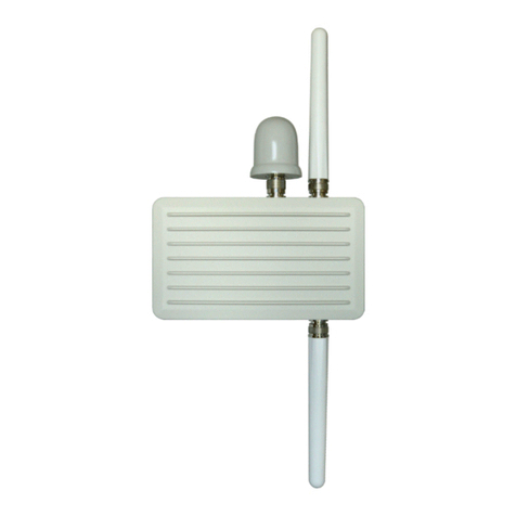
Unex RSU-352 Series User manual

Doc. No: Unex-QSG-21-002
1/21
A printed version of this document is an uncontrolled copy
© 2023 Unex Technology Corporation – Company Confidential
Document Number
Unex-QSG-21-002
Revision
0.8
Authors
Nidor Huang
Quick Start Guide
for
RSU-352 Family
Product Variants
Model
Description
RSU-352
V2X Roadside Unit, 0A1
RSU-352EC
C-V2X Roadside Unit, V2Xcast® - Europe ETSI C-V2X stack, 0A1
RSU-352ED
DSRC-V2X Roadside Unit, V2Xcast® - Europe ETSI ITS-G5 stack, 0A1
RSU-352UC
C-V2X Roadside Unit, V2Xcast® - US C-V2X stack, 0A1
RSU-352UD
DSRC-V2X Roadside Unit, V2Xcast® - US DSRC/WAVE stack, 0A1
Reviewers
Department
Name
Acceptance Date
Note
PD
Nidor Huang
2023/03/24
RD
P.C Kang
2023/03/24
Modification History
Revision
Date
Originator
Comment
0.1
2021/08/23
Nidor Huang
Creating document
0.2
2021/10/12
Nidor Huang
Adding product variants
Adding product characteristics
Adding dimensions and weight
0.3
2021/11/18
Nidor Huang
Updating temperature range
Updating mechanical drawing
0.4
2022/04/15
Nidor Huang
Adding GNSS antenna detection mechanism
Adding V2X antenna detection mechanism
0.5
2022/06/28
Nidor Huang
Adding GORE® Vent
0.6
2022/12/30
Nidor Huang
Updating product variants to 352 series
Updating functional block diagram
0.7
2023/03/03
Nidor Huang
Updating Unex BSP interface settings
Updating mounting bracket instructions

Doc. No: Unex-QSG-21-002
2/21
A printed version of this document is an uncontrolled copy
© 2023 Unex Technology Corporation – Company Confidential
Revision
Date
Originator
Comment
0.8
2023/03/24
Nidor Huang
Updating Unex logo
Adding GNSS reset in Unex BSP interface settings
Adding installation precaution about surge protection

Doc. No: Unex-QSG-21-002
3/21
A printed version of this document is an uncontrolled copy
© 2023 Unex Technology Corporation – Company Confidential
TABLE OF CONTENTS
1. Objective...................................................................................................5
2. Reference .................................................................................................5
3. Limited Warranty Policy ............................................................................5
4. Safety Guidelines......................................................................................6
5. Product Appearance .................................................................................6
6. Functional Block Diagram.........................................................................8
7. Electrical Characteristics ..........................................................................8
7.1. Absolute Maximum Ratings .................................................................................. 8
7.2. Recommended Operating Conditions................................................................... 9
7.3. Power Consumption.............................................................................................. 9
8. I/O Interfaces ..........................................................................................10
8.1. Status LED .......................................................................................................... 10
8.2. PoE (Power-Over-Ethernet)................................................................................ 10
8.3. 5.9GHz V2X .........................................................................................................11
8.4. GNSS .................................................................................................................. 12
8.4.1. GNSS Antenna Detection ..................................................................... 12
9. Accessories ............................................................................................13
9.1. GORE® Vent........................................................................................................ 13
9.2. Surge Protector ................................................................................................... 14
9.3. Cable Gland ........................................................................................................ 14
9.4. Mounting Bracket ................................................................................................ 15
10. Dimensions and Weight ..........................................................................20
11. Software Settings....................................................................................21
LIST OF FIGURES
Figure 1: RSU-352 series package content .............................................................................. 7
Figure 2: RSU-352 series complete assembly appearance...................................................... 7
Figure 3: Functional block diagram ........................................................................................... 8
Figure 4: Status LED ............................................................................................................... 10
Figure 5: PoE port.................................................................................................................... 10
Figure 6: V2X antenna ports and V2X antennas EX-53...........................................................11
Figure 7: GNSS antenna port and GNSS antenna.................................................................. 12
Figure 8. The GORE® Vent...................................................................................................... 13
Figure 9: PoE surge protector ................................................................................................. 14
Figure 10: Cable gland drawing............................................................................................... 15
Figure 11: RSU-352 mounting bracket assembly (horizontal) steps ....................................... 16

Doc. No: Unex-QSG-21-002
4/21
A printed version of this document is an uncontrolled copy
© 2023 Unex Technology Corporation – Company Confidential
Figure 12: RSU-352 mounting bracket assembly (vertical) steps ........................................... 17
Figure 13: An example illustration of RSU-352 mounting on a horizontal mast/gantry........... 17
Figure 14: An example illustration of RSU-352 mounting on a vertical mast/post .................. 18
Figure 15: Earth wire connection position (left), earth wire and earth wire screw (right) ........ 19
Figure 16: Mounting bracket dimensions ................................................................................ 20
Figure 17: Mechanical dimensions .......................................................................................... 20
LIST OF TABLES
Table 1. Absolute maximum ratings........................................................................................... 8
Table 2. Recommended operating conditions ........................................................................... 9
Table 3: Power consumption ..................................................................................................... 9
Table 4: LED function .............................................................................................................. 10
Table 5: V2X antenna status.....................................................................................................11
Table 6: GNSS antenna status ................................................................................................ 13
Table 7: Dimensions and weight.............................................................................................. 21
Table 8: Unex BSP interface settings ...................................................................................... 21

Doc. No: Unex-QSG-21-002
5/21
A printed version of this document is an uncontrolled copy
© 2023 Unex Technology Corporation – Company Confidential
1. Objective
The purpose of this document is to provide necessary information to help setup and
installation of RSU-352 series products. To provide for safe installation and operation of the
equipment, read the safety guidelines at the beginning of this manual and follow the
procedures outlined in the following chapters before connecting power to RSU-352. Keep
this operating manual handy and distribute to all users, technicians and maintenance
personnel for reference.
2. Reference
•Unex RSU-352 datasheet
•61-00021-00_RSU-352_0A1_Drawing
•80-00032_EX-40_Drawing_B
3. Limited Warranty Policy
Unex Technology Corporation selling the product warrants that commencing from the
date of shipment to customer and continuing for a period of twelve (12) months. This limited
warranty extends only to the original customer of the product. Customer's sole and
exclusive remedy and the entire liability of Unex under this limited warranty will be, at
Unex's option, return for repair to Unex's repair center with freight and insurance prepaid
or shipment of a replacement within the warranty period or a refund of the purchase price
if the hardware is returned to Unex. Unex’s obligations hereunder are conditioned upon the
return of affected hardware in accordance with Unex's service center's then-current Return
Material Authorization (RMA) procedures.
This warranty does not cover:
•Products found to be defective after the warranty period has expired.
•Products subjected to misuse or abuse, whether by accident or other causes.
Such product conditions will be determined by Unex at its sole and unfettered
discretion.
•Products damaged due to a natural disaster, including but not limited to
lightning, flooding, earthquake, or fire.
•Software products.
•Products dismantled or opened by unauthorized persons. Please contact a
representative of Unex if you need advanced technical support.

Doc. No: Unex-QSG-21-002
6/21
A printed version of this document is an uncontrolled copy
© 2023 Unex Technology Corporation – Company Confidential
•Products with an altered and/or damaged serial number.
•Loss of data or software.
•Products that have been updated, reworked, or improperly tested by the
Customer, or by a third party at the request of the Customer.
•Customized and original design manufacturer (ODM) products. The warranty
terms for customized and ODM products should be defined in the contract
that governs the project.
4. Safety Guidelines
•Keep working area clean and dry while assembling/installing
•When operating under extreme temperature conditions, environmental control
measures (e.g., heating, cooling) should be considered.
•Always make sure the metal enclosure is connected to a well-grounded metal
structure.
•Make sure every screw has been fastened, including the mounting bracket, pole
clamps and earth wire.
•Make sure every accessory has been fastened, including the V2X antennas, GNSS
antenna, PoE surge protector and cable gland.
5. Product Appearance
An RSU-352 series package contains the following items:
•RSU-352 x1
•V2X antenna x2
•GNSS antenna x1
•PoE surge protector x1
•Cable gland x1
•Mounting bracket set x1
•Earth wire (1 Meter) x1
The photos shown in this document may seem different from actual product. However,
the differences do not affect actual functionalities.

Doc. No: Unex-QSG-21-002
7/21
A printed version of this document is an uncontrolled copy
© 2023 Unex Technology Corporation – Company Confidential
Figure 1: RSU-352 series package content
Figure 2: RSU-352 series complete assembly appearance

Doc. No: Unex-QSG-21-002
8/21
A printed version of this document is an uncontrolled copy
© 2023 Unex Technology Corporation – Company Confidential
6. Functional Block Diagram
Figure 3: Functional block diagram
7. Electrical Characteristics
7.1. Absolute Maximum Ratings
Over operating free-air temperature range (unless otherwise noted).
Table 1. Absolute maximum ratings
Parameters
Conditions
Min.
Max.
Unit
Storage Temperature
-
-40
70
°C
Supply Voltage
PoE *1
-
60
V
V2X maximum input level
-
-
10
dBm
GNSS maximum input level
-
-
-10
dBm
Note: *1: Powered by an 802.3af/at PSE
Note: (1) Operation outside the Absolute Maximum Ratings may cause permanent device damage. Absolute
Maximum Ratings do not imply functional operation of the device at these or any other conditions
beyond those listed under Recommended Operating Conditions. If used outside the Recommended
Operating Conditions but within the Absolute Maximum Ratings, the device may not be fully functional,
and this may affect device reliability, functionality, performance, and shorten the device lifetime.
(2) All voltages are with respect to network GND.

Doc. No: Unex-QSG-21-002
9/21
A printed version of this document is an uncontrolled copy
© 2023 Unex Technology Corporation – Company Confidential
7.2. Recommended Operating Conditions
Over operating free-air temperature range (unless otherwise noted).
Table 2. Recommended operating conditions
Parameters
Conditions
Min.
Typ.
Max.
Unit
Ta (Ambient operating temperature)
Free-air temp.
-40
25
85 *1
°C
Supply voltage
PoE *2
36
48
57
V
V2X antenna gain
5850-5925MHz
-
-
7.6
dBi
V2X sensitivity
PER ≤10%
-92
-
-
dBm
PER ≤10%,
-40 - +85 °C
-82
-
-
dBm
V2X maximum input level
PER ≤10%
-
-
-30
dBm
V2X adjacent channel rejection
-
13
-
-
dB
V2X non-adjacent channel rejection
-
29
-
-
dB
V2X output power
Spectrum mask
Class C
-
-
20
dBm
GNSS antenna gain
Antenna Gain
-
-
2.4 *3
2.85 *4
dBic
LNA Gain *5
24
27
30
dB
GNSS sensitivity (C/N0)
Acquisition
22
30
45
dB-
Hz
GNSS antenna bias
IANT ≤20mA
3.0
-
3.3
V
GNSS antenna detection current
IANT *6
12
-
58
mA
Note: *1: Excluding V2X antennas. Ta of V2X antenna is -40 ~ +70°C
*2: Powered by an 802.3af/at PSE
*3: Measured at 1575MHz
*4: Measured at 1602MHz
*5: GNSS LNA bias = 3.0V
*6: IANT under Min. = OPEN; IANT over Max. = SHORT; IANT between Min/Max. = NORMAL.
7.3. Power Consumption
RSU-352 is an 802.3af PD (powered device) and should be powered with an
802.3af/802.3at PoE PSE (power sourcing equipment).
Table 3: Power consumption
Condition
Power Consumption
Temp.
Power Source
Voltage (V)
Low *1
Typical *2
High *3
25°C
802.3af PoE PSE
54.3
0.06A
(3.26W)
0.06A
(3.26W)
0.11A
(5.97W)
85°C
802.3af PoE PSE
54.3
0.07A
(3.80W)
0.07A
(3.80W)
0.12A
(6.52W)

Doc. No: Unex-QSG-21-002
10/21
A printed version of this document is an uncontrolled copy
© 2023 Unex Technology Corporation – Company Confidential
Note: *1: RX only
*2: TX @ 1% duty cycle (CH172, 20dBm, 6Mbps, 750B, 10Hz)
*3: TX @ 100% duty cycle (CH172, 20dBm)
8. I/O Interfaces
8.1. Status LED
Figure 4: Status LED
Table 4: LED function
LED Status
Description
Blinking Green
Start-up
Solid Green
Operational
Amber
FW upgrade
Red
Fault
Note: Please see TABLE 8: UNEX BSP INTERFACE SETTINGS for Status LED BSP settings. The definition of each
status and its related behavior should be implemented by the user.
8.2. PoE (Power-Over-Ethernet)
Figure 5: PoE port
RSU-352 has one Gigabit Ethernet port which supports 10/100/1000Mbps connection.
Status LED
PoE

Doc. No: Unex-QSG-21-002
11/21
A printed version of this document is an uncontrolled copy
© 2023 Unex Technology Corporation – Company Confidential
It is suggested to use an Ethernet cable compatible with Cat5e or above standard for best
connection speed.
This Ethernet port also acts as a 12W PoE (802.3af) PD (powered device). It supports
both mode A and mode B PSE (power sourcing equipment). Passive PoE is not supported.
8.3. 5.9GHz V2X
Figure 6: V2X antenna ports and V2X antennas EX-53
RSU-352 provides two 5.9GHz V2X antenna connectors. Receptacle connectors are
Type-N. These V2X ports are surge protected (5KA min with 8/20 μs, 10KV min with 1.2/50
μs). A pair of Type-N V2X antennas (EX-53, 7.6dBi omni-directional) are also provided in
RSU-352 package.
The V2X antenna ports has a built-in antenna detection function. This detection
mechanism only works with the stock EX-53 antennas provided.
Table 5: V2X antenna status
Antenna Status
Value
Command
OPEN
616-1023
V2X0: cat /sys/bus/iio/devices/iio\:device0/in_voltage4_raw
V2X1: cat /sys/bus/iio/devices/iio\:device0/in_voltage5_raw
NORMAL
410-615
SHORT
0-409
V2X0 ANT
Type N
V2X1 ANT
Type N

Doc. No: Unex-QSG-21-002
12/21
A printed version of this document is an uncontrolled copy
© 2023 Unex Technology Corporation – Company Confidential
8.4. GNSS
Figure 7: GNSS antenna port and GNSS antenna
RSU-352 provides one GNSS antenna connector. This GNSS antenna port is Type-N.
This GNSS port is surge protected (5KA min with 8/20 μs, 10KV min with 1.2/50 μs).
An active GNSS antenna (EX-33) is also provided in RSU-352 package.
For stable fix acquisition, at least 4 satellites with enough signal strength (C/N0 value
above 30 dB-Hz) are required. If the signal strength goes below 30 dB-Hz, the fix will
become unstable.
8.4.1. GNSS Antenna Detection
The antenna detection mechanism is a 2-step process: First check the signal strength.
If the signal strength drops to zero, then check the antenna status flag.
When all the C/N0 values becomes null, it means that the GNSS antenna or its cable
may either become detached or damaged. The GNSS antenna port has a built-in antenna
detection function. The detection mechanism is based on the current consumption of an
active antenna (IANT). If the active antenna consumes less current than 12 mA, then it is
considered as the OPEN status; if the antenna consumes more than 58 mA, then it is
considered as the SHORT status. Anything between 12-58 mA is considered as the
NORMAL status.
The GNSS 3.3V antenna bias will be continuously supplied in OPEN/NORMAL status.
Once the SHORT status is triggered, the SHORT flag will persist, and the 3.3V bias will be
turned off until the reset of the GNSS module. After the reset of the GNSS module, the
detection process will start all over again.
GNSS ANT
Type N

Doc. No: Unex-QSG-21-002
13/21
A printed version of this document is an uncontrolled copy
© 2023 Unex Technology Corporation – Company Confidential
It is possible for a good active antenna to be reported OPEN because it consumes less
current than 12 mA (e.g., the bundled EX-33 antenna consumes only 8 mA), or a good
passive antenna to be considered SHORT because it is DC shorted (e.g., a slot antenna).
However, as long as there are more than 4 satellites with enough signal strength (C/N0
value above 30 dB-Hz), the GNSS is in good state.
The antenna status flag is reported in a proprietary NMEA message:
$PSTMANTENNASTATUS,<status>*<checksum><cr><lf>
where <status> can be:
•0 - The antenna current is in the normal range (NORMAL)
•1 - The antenna current is below the normal range (OPEN)
•2 - The antenna current is above the normal range (SHORT)
Table 6: GNSS antenna status
Antenna
Status
Current
Consumption (mA)
3.3V bias
NMEA Sentence
OPEN
< 12
ON
$PSTMANTENNASTATUS,1*4C
NORMAL
between 12- 58
ON
$PSTMANTENNASTATUS,0*4D
SHORT
> 58
Turned OFF once triggered
$PSTMANTENNASTATUS,2*4F
9. Accessories
9.1. GORE® Vent
A GORE® Vent is pre-installed to continuously equalize the pressure inside the RSU
enclosure with the atmosphere, while the PTFE membrane prevents the water and dust
ingress at the same time. This vent manages common outdoor weather conditions such as
precipitation or condensation, and as a result, it increases the service life of the RSU.
Figure 8. The GORE® Vent
GORE® Vent

Doc. No: Unex-QSG-21-002
14/21
A printed version of this document is an uncontrolled copy
© 2023 Unex Technology Corporation – Company Confidential
9.2. Surge Protector
RSU-352 is powered by PoE. The PoE surge protector should be installed on the PoE
port before connecting Ethernet cable. Please follow the instruction below for installation:
1 Extend the short RJ45 cable on the surge protector
2 Plug the short RJ45 cable into the PoE port on RSU-352
3 Screw the surge protector over the PoE port until fastened
Figure 9: PoE surge protector
9.3. Cable Gland
To ensure weather resistance, always connect the Ethernet cable with the cable gland
on the cable outlet. Please follow the instruction below for installation:
1 Cable outer diameter: 4.5-6.5mm.
2 Insert RJ45 cable through sealing nut, clip, body and O-ring in a row. (See above
drawing for parts direction)
3 Securely connect the RJ45 connector with the RJ45 port.
4 Fasten the body to the RJ45 port, with O-ring side facing the metal housing.
5 Sit the seals firmly into the body.
6 Push the clip and seals all the way down to the body.
7 Fasten sealing nut with the body.

Doc. No: Unex-QSG-21-002
15/21
A printed version of this document is an uncontrolled copy
© 2023 Unex Technology Corporation – Company Confidential
Figure 10: Cable gland drawing
9.4. Mounting Bracket
For best RF signal coverage, it is best to install RSU-352 on a horizontal mast/gantry
and to keep it away from any large metal object nearby (FIGURE 13). However, RSU-352
can also be installed on a vertical post or on a wall if needed (FIGURE 14). The length of
the earth wire is 1 meter long.
The diameter of the mast/post should be between 78-101mm. The total weight of RSU-
352 (including antennas, PoE surge protector, mounting bracket, earth wire and cable gland)
is about 2.7 kg. Before installation, always make sure the structural strength of the
mast/post/wall can hold the extra weight of RSU-352.
Aluminum corrosion deposits may start to build on the mounting hole threads over time
if an RSU-352 is installed by the seashore or in an environment where salt mist could
become a problem. As a general rule of thumb, it is highly recommended to always apply
a generous amount of waterproof/anti-seize lubricant (e.g., LOCTITE LB 8150) over the
threads of the mounting screws and the earth wire screw before installing.

Doc. No: Unex-QSG-21-002
16/21
A printed version of this document is an uncontrolled copy
© 2023 Unex Technology Corporation – Company Confidential
Caution
An RSU would be vulnerable to electric overstress if not installed
properly. In order to avoid electric overstress related hardware failures,
please make sure to follow the instructions below before installation:
1 Surge Protector
1.1 Always install the surge protector on the PoE port.
2 If Proper Earthing Available
2.1 Make sure the electric potential of the metal structure where
the earth wire connects to equals to the actual earth potential
before connecting the earth wire.
2.2 The earth wire should be connected to a metal structure with
less than 10 ohms of earthing resistance.
2.3 Connect the earth wire (green jacket) between the RSU and
the well-grounded metal structure (FIGURE 15).
3 If Proper Earthing Not Available
3.1 If a properly earthed metal structure is not available, make
sure that the RSU enclosure and the PSE earth wire are at
the same electric potential.
3.2 Connect the RSU and the PSE via a STP (shielded twisted
pair) cable instead of an UTP (unshielded twisted pair) cable.
3.3 Insulate the RSU and the mounting bracket from the metal
structure.
3.4 Remove the earth wire to achieve proper insulation.
Figure 11: RSU-352 mounting bracket assembly (horizontal) steps
M5x10

Doc. No: Unex-QSG-21-002
17/21
A printed version of this document is an uncontrolled copy
© 2023 Unex Technology Corporation – Company Confidential
Figure 12: RSU-352 mounting bracket assembly (vertical) steps
Figure 13: An example illustration of RSU-352 mounting on a horizontal mast/gantry
M5x10

Doc. No: Unex-QSG-21-002
18/21
A printed version of this document is an uncontrolled copy
© 2023 Unex Technology Corporation – Company Confidential
Figure 14: An example illustration of RSU-352 mounting on a vertical mast/post

Doc. No: Unex-QSG-21-002
19/21
A printed version of this document is an uncontrolled copy
© 2023 Unex Technology Corporation – Company Confidential
Figure 15: Earth wire connection position (left), earth wire and earth wire screw (right)
Earth wire screw
M4x8

Doc. No: Unex-QSG-21-002
20/21
A printed version of this document is an uncontrolled copy
© 2023 Unex Technology Corporation – Company Confidential
10.Dimensions and Weight
Figure 16: Mounting bracket dimensions
Figure 17: Mechanical dimensions
This manual suits for next models
6
Table of contents
Other Unex Network Hardware manuals