
Aurora243 Outdoor 2x10W TDD gNodeB Installation Guide
vi
List of Figures
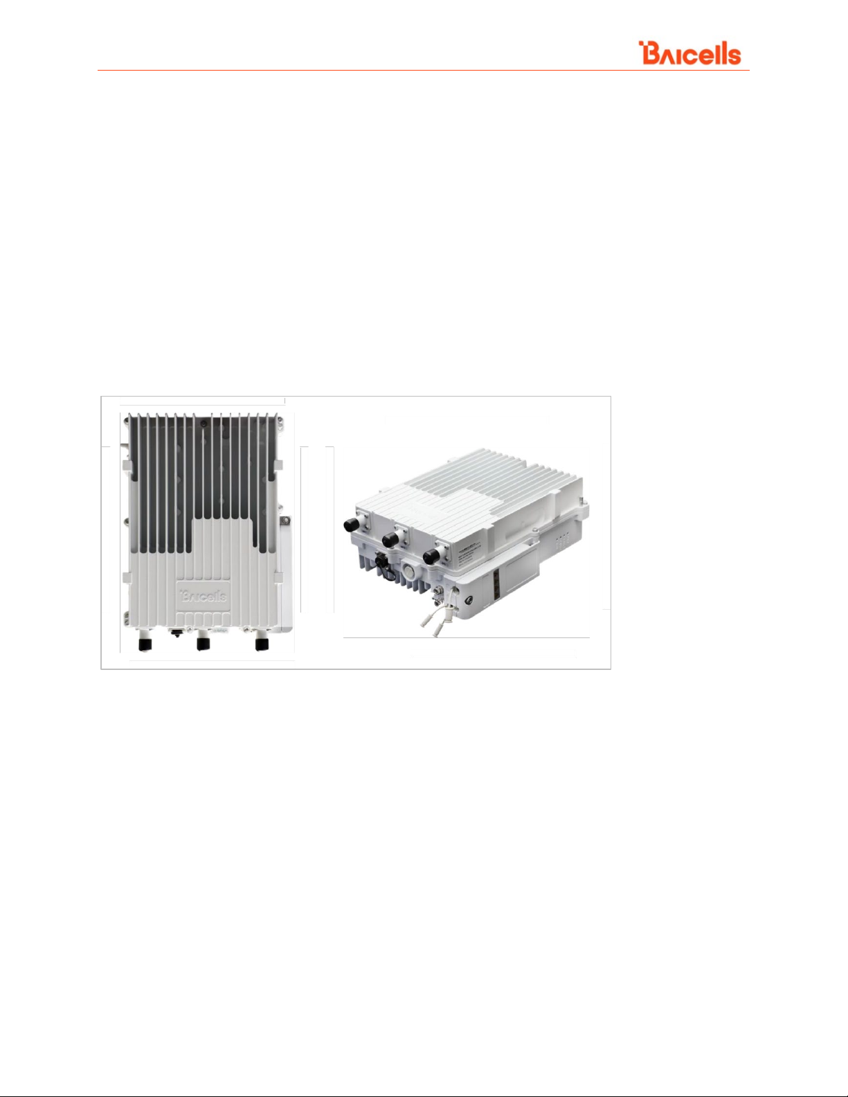
Figure 1-1: Aurora243 gNodeB ...........................................................................................................................8
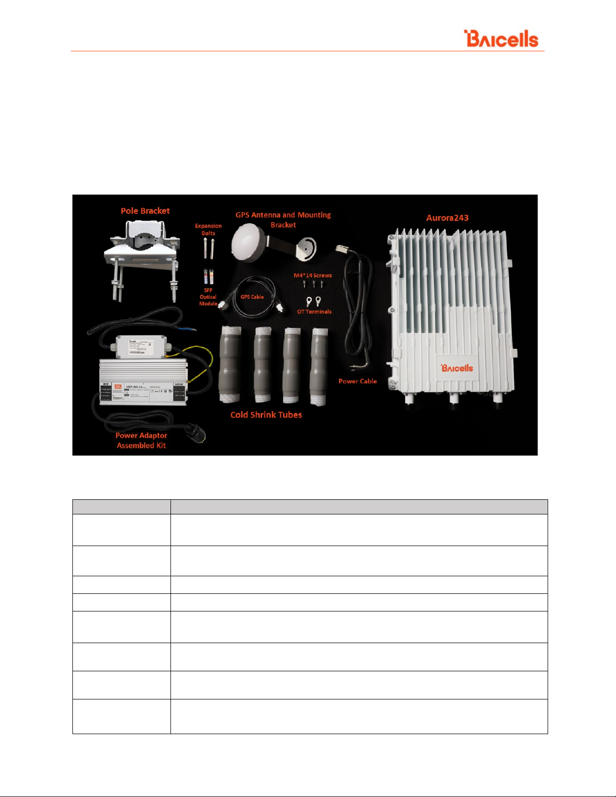
Figure 2-1: Aurora243 Pack Out........................................................................................................................10
Figure 2-2: LEDs and Interfaces ........................................................................................................................11
Figure 2-3: Weatherproofing ............................................................................................................................14
Figure 3-1: Installation Process Overview.........................................................................................................15
Figure 3-2: GPS Installation Requirements .......................................................................................................16
Figure 3-3: GPS Antenna Installation................................................................................................................16
Figure 3-4: Diameter and Height Requirements...............................................................................................17
Figure 3-5: Device with Pre-assembled Mounting Bracket ..............................................................................17
Figure 3-6: Pole or Wall Mounting Bracket.......................................................................................................18
Figure 3-7: Turn Clamps....................................................................................................................................18
Figure 3-8: Place Bracket on Pole .....................................................................................................................18
Figure 3-9: Attach gNB to Bracket.....................................................................................................................19
Figure 3-10: Tighten Bolt and Screw.................................................................................................................19
Figure 3-11: Wall Mounting Bracket .................................................................................................................20
Figure 3-12: Mark Drilling Location ..................................................................................................................20
Figure 3-13: Install Expansion Bolts..................................................................................................................20
Figure 3-14: Hang Bracket.................................................................................................................................21
Figure 3-15: Completed Installation .................................................................................................................21
Figure 3-16: GPS Antenna Weatherproofing ....................................................................................................23
Figure 3-17: Power Adapter..............................................................................................................................25
Figure 3-18: DC Power Terminal .......................................................................................................................25
Figure 3-19: AC Power Terminal .......................................................................................................................26
Figure 3-20: Pole Grounding.............................................................................................................................27
Figure 3-21: Grounding Screws.........................................................................................................................28
Figure 3-22: GPS Antenna Grounding...............................................................................................................28
Figure 3-23: Power Adapter Grounding............................................................................................................29
Figure 4-1: Network Connection ......................................................................................................................30
Figure 4-2: IP Setting on PC ..............................................................................................................................32
Figure 4-3: Login ...............................................................................................................................................32
Figure 4-4: Home Page......................................................................................................................................33
Figure 4-5: Upgrade Firmware..........................................................................................................................33
Figure 4-6: Configure the IP address of CU.......................................................................................................34
Figure 4-7: Configure the IP Address of DU......................................................................................................35
Figure 4-8 Configure the IP address of WAN Interface-Aurora243 ..................................................................35
Figure 4-9 Configure PLMNID/Slice/TAC-Aurora243 ........................................................................................36
Figure 4-10: Reboot ..........................................................................................................................................36
Figure 4-11: Verify Operational Status..............................................................................................................37


