Uni-ram URS500 Series User manual

USER MANUAL
URS500 AND URS600 SERIES
MODELS
URS500 URS600
URS500EP2 URS600EP2
UNI-RAM CORPORATION • ONTARIO • CANADA
Revision 2019-07
URS500 / URS600 URS500EP2 / URS600EP2

2
MANUAL - SOLVENT RECYCLERS - URS500, 600, 500EP2, 600EP2 Revision 2019-07
CONTENTS
INTRODUCTION ................................................................................................................................... 3
SAFETY APPROVALS, CAUTIONS AND WARNINGS ........................................................................ 3
FEATURES AND SPECIFICATIONS .................................................................................................... 4
SAFETY FEATURES ............................................................................................................................ 4
PREPARATION AND SETUP .............................................................................................................. 5
LOCATION AND CONNECTION ......................................................................................................... 5-6
SOLVENT REQUIREMENTS AND DEFINITIONS ................................................................................ 6
SOLVENT TRANSFER (EP2 MODELS) .............................................................................................. 6-7
OPERATING PROCEDURES ........................................................................................................... 8-11
SYSTEM SPECIFICATIONS .............................................................................................................. 12
THEORY OF OPERATION ................................................................................................................. 13
TROUBLESHOOTING GUIDE ........................................................................................................... 14-14
ERROR CODES ................................................................................................................................ 16-17
SERVICE PROCEDURES .................................................................................................................. 19-20
REPLACEMENT PARTS .................................................................................................................... 20
WARRANTY ....................................................................................................................................... 21

3
MANUAL - SOLVENT RECYCLERS - URS500, 600, 500EP2, 600EP2 Revision 2019-07
INTRODUCTION
Uni-ram holds many patents on designs used in its innovative products. Every machine is tested for com-
pliance with Quality Assurance standards. Follow the instructions on preparation, use and operation to
operate this machine safely and eff ectively. Ensure that this manual is readily available to the operator at
all times. If you have any questions about the operation of this machine, contact:
North America:
Uni-ram Technical Service
1-800-417- 9133
Other Continents:
Contact Your Supplier
CAUTIONS AND WARNINGS
• The operator should wear protective clothing in accordance with local safety and environmental
regulations, with a minimum of face goggles and gloves along with an apron and respirator if required.
• Always disconnect the power source before performing maintenance.
• DO NOT SMOKE OR USE THIS EQUIPMENT NEAR A POTENTIAL SOURCE OF IGNITION SUCH
AS SPARKS OR AN OPEN FLAME. This unit must be located at least 6 feet (1.8 m) from all potential
sources of ignition including electrical receptacles, switches, pilot lights, fi xtures and contacts when
installed in a non - hazardous locations.
• The ambient temperature must be between 5°C (41°F) to 35°C (95°F).
• DO NOT RECYCLE NITROCELLULOSE WHICH IS EXTREMELY VOLATILE. IT AUTOMATICALLY
IGNITES AT 135°C TO 166°C (275°F TO 330°F). Do not install, operate or maintain this equipment
where the auto ignition temperature of the solvent is lower than 250°C (482°F).
• Do not install, operate or maintain this equipment where the auto ignition temperature of the hazard-
ous atmosphere(s) is lower than 250°C (482°F).
• Solvents that are recycled can be fl ammable. Establish and follow safe practices to store and handle
solvents.
• Units must be installed by a qualifi ed electrician and according to applicable laws.
SERIAL NUMBER
The serial nunber of this unit is located on the back of the unit in a black and silver label. The serial
number should be recorded and fi led in a safe place for future reference regarding quality and/or safety
issues.
SAFETY APPROVALS
This unit is certifi ed under UL standards U2208 and CSA standards C22.2 No. 30 and No. 88 by ETL for
use in non-hazardous locations as well as for use in hazardous locations Class 1, Division 1, Group D
– T2C and and Class 1, Division 2, Group D -T2C.

4
MANUAL - SOLVENT RECYCLERS - URS500, 600, 500EP2, 600EP2 Revision 2019-07
FEATURES AND SPECIFICATIONS
All Uni-ram Solvent Recyclers feature rapid-start direct electric heating of solvent (so there is no dia-
thermic oil to change) as well as high-effi ciency condensers, air cooled with a motor driven fan. All of the
Recyclers can be used with any Uni-ram Automatic Apray Gun Cleaner. The “E” models are designed to
be linked directly to a Uni-ram “E” series Automatic Spray Gun Cleaner or to an external container. The
direct connection creates a self-contained Recycling System allowing Timer-controlled Transfer In and
Out between the Solvent Recycler and the other component.
MODEL URS500 URS600 URS500EP2 URS600EP2
VOLTAGE(V) 110/120 220/240 110/120 220/240
CURRENT USAGE (A) 13.3 6.7 13.3 6.7
RECOMMENDED CIRCUIT AMPS 20 15 20 15
EXPLOSION PROOF PLUG /
RECEPTACLE
5-20P / 5-20R 6-20P / 6-20R 5-20P / 5-20R 6-20P / 6-20R
TANK CAPACITY 5 US GAL (20L) 5 US GAL (20L) 5 US GAL (20L) 5 US GAL (20L)
CONSENSER AND FITTING COPPER COPPER COPPER COPPER
LID GASKET NEOPRENE** NEOPRENE** NEOPRENE** NEOPRENE**
SOLVENT TRANSFER SYSTEM NO NO YES YES
DIMENSIONS (WDH”) 19 X 19 X 45 20 X 20 X 45 19 X 19 X 45 20 X 20 X 45
WEIGHT (LB/KG) 130/59 130/59 140/64 140/64
** ALSO AVAILABLE IN VITON OR TEFLON
Safety Features:
• Certifi ed to UL standards U2208 and CSA standards C22.2 No. 30 and No. 88 by ETL. Approved
for use in non hazardous locations as well as approved for use in hazardous locations Class 1,
Division 1, Group D and Class 1, Division 2, Group D.
• Explosion proof construction and intrinsically safe electric circuitry.
• Computer controlled with many built-in safety programs including temperature control of all criti-
cal points including tank, condenser and fan motor. Power is cut when the temperature at any of
these points rises above a pre-set level. Operation also terminates when other abnormal conditions
exist (eg: boiling does not start on time or the distillation process takes too long).
• Automatic pressure relief lid system prevents pressure in the Distillation Tank from exceeding 0.5
to 1.0 psi. (0.035 to 0.070 kg/cm2).
• Self Diagnostic error messages are displayed on the Display Panel.
• Dual lid cover system.
• Compact, enclosed cabinet for safe storage of the Solvent Receiving Container inside the cabinet.
Operating Features:
• Rapid-start due to direct electric heating of solvent, no diathermic oil to change.
• Short cool-down time. High effi ciency condenser, air cooled with motor driven fan.
Warranty: 1 year on unit, 2 years on pump.

5
MANUAL - SOLVENT RECYCLERS - URS500, 600, 500EP2, 600EP2 Revision 2019-07
PREPARATION AND SETUP
• Carefully inspect the shipping carton for any sign of transport damage.
• Carefully remove the unit from the shipping carton.
• Check the unit for damage. Report any transport damage immediately to the carrier and your
vendor. Initiate a freight claim with the carrier. The manufacturer is not responsible for freight dam-
age.
• A Liner Bag and Retainer Ring are already installed inside the distillation tank.
• Check the Accessory Kit for the parts listed below. If any parts are missing, contact your supplier. Ad-
ditional consumables and accessories are also listed.
• Level the unit using the adjustable feet and install the Door Handle.
• For models with the Solvent Transfer System (EP2 Models), install the Solvent Transfer Hoses and the
Air Supply Kit. (See instructions on Pages 7-8).
LOCATION AND CONNECTION
This unit is certifi ed for use in non-hazardous locations and hazardous locations
Class 1, Division 1 Group D and Class 1, Division 2, Group D.
• Non-hazardous Location:
The unit must be located outside of a hazardous location. We recommend that the unit be located at
least 6 feet from any potential source of ignition such as electrical receptacles, switches, pilot lights,
fi xtures, contacts and similar equipment. To clarify the defi nition of an appropriate location, contact
your local authority. Use the explosion proof plug and receptacle shown in the Chart under FEATURES
AND SPECIFICATIONS. The explosion proof plug is provided with the unit. The customer is respon-
sible for acquiring the matching explosion proof receptacle. The power cord is connected to the power
CAUTION:
USE ONLY GENUINE UNI-RAM
LINER BAGS WHICH ARE 2 MIL
THICK, LIGHT BLUE IN COLOUR
WITH A SAWTOOTH EDGE AND A
3/16” WELD.
THEY ARE SPECIALLY MANUFAC-
TURED TO BE STRONG, HEAT
RESISTANT AND CHEMICAL
RESISTANT.
USE OF A NON-UNI-RAM LINER
BAG MAY VOID THE WARRANTY.
ACCESSORY KIT (Included Parts)
All Models Replacement Part Number
Manual NA
Lid Gasket, Standard (Neoprene)* 770-2150N
Liner Bag, 2 Spares See below for re-order numbers
Door Handle & 2 Screws 120-318 & 909-404S
Solvent Outlet Tube 770-8131
EP2 Models Only
Transfer Hoses and Fittings (EP2 Series) KIT-TRANSHOSES-A
Air supply Kit (EP2 Series) KIT-AIRSUPPLY-E

6
MANUAL - SOLVENT RECYCLERS - URS500, 600, 500EP2, 600EP2 Revision 2019-07
supply only by a qualifi ed electrician in accordance with the National Electrical Code.
• Hazardous Location:
In hazardous locations (Class 1, Division 1, Group D and Class 1, Division 2, Group D), use the explo-
sion proof plug and receptacle shown in the Chart under FEATURES AND SPECIFICATIONS. The
explosion proof plug is provided with the unit. The customer is responsible for acquiring the matching
explosion proof receptacle. The power cord must be connected to the main power supply by a quali-
fi ed electrician, in accordance with the National Electrical Code.
Select a location that meets EACH AND EVERY requirement, as follows ...
LOCATION AND CONNECTION (continued)
1) Comply with the instructions in the section, CAUTIONS AND WARNINGS, page 3.
2) Position the solvent recycler in a location so that there is at least 6 inches (15 cm) of space all around
the unit. Ensure that the safety lid and door freely opens fully and a container for receiving the distilled
solvent can freely move in and out of the cabinet. The unit must be in a location where people or equip-
ment cannot disturb the cable or connection. The cord must be connected directly to the main power sup-
ply; an extension cord cannot be used.
3) Connect the unit to a dedicated 15 A branch circuit.
Power Requirements: URS500/ URS500S/ series: 110/ 120 volts AC, 13.3 A
URS600/ URS600S/ series: 220/ 240 volts AC, 6.7 A
“READY (L)” and / or “READY (H)” LED Light on the Control Panel comes on when power is supplied to
the unit
SOLVENT REQUIREMENTS
This unit recycles fl ammable solvents and combustible solvents. Flammable liquids include lacquer thin-
ner, paint thinner, acetone and other paint diluents. Flammable Solvents have a fl ash point below 38.7°C
(100°F). These solvents are commonly used in the industry as a cleaning solvent, or as a paint diluent.
Dirty solvent to be distilled must meet each requirement described below. The MSDS, material solvent
data sheet, provides data on the properties of the pure, clean solvent.
1) The BP (Boiling Point) of the dirty solvent must be less than 200°C (392°F). BP increases with greater
contamination.
Note: Recycle recently contaminated solvent only. Standing solvent can become acidic over time.
2) The auto-ignition temperature of the solvent to be distilled must be higher than 260°C (500°F) for safe
operation. Do not recycle Nitrocellulose. The auto ignition temperature is 135°C (275°F).
Note: Do not recycle both paint diluent and parts washer solvent in the same unit. When paint
diluent or lacquer thinner is contaminated with parts washer solvent “ FISH EYE” problems may
result.
Waste Residue
The waste residue of some paints will remain moist after recycling due to the composition of the paint
itself. A dry waste residue is not guaranteed.
Defi nitions
Flash Point: The lowest temperature at which the vapor of a solvent can be made to ignite in air.
Auto-ignition temperature: the temperature at which solvent ignites by itself.
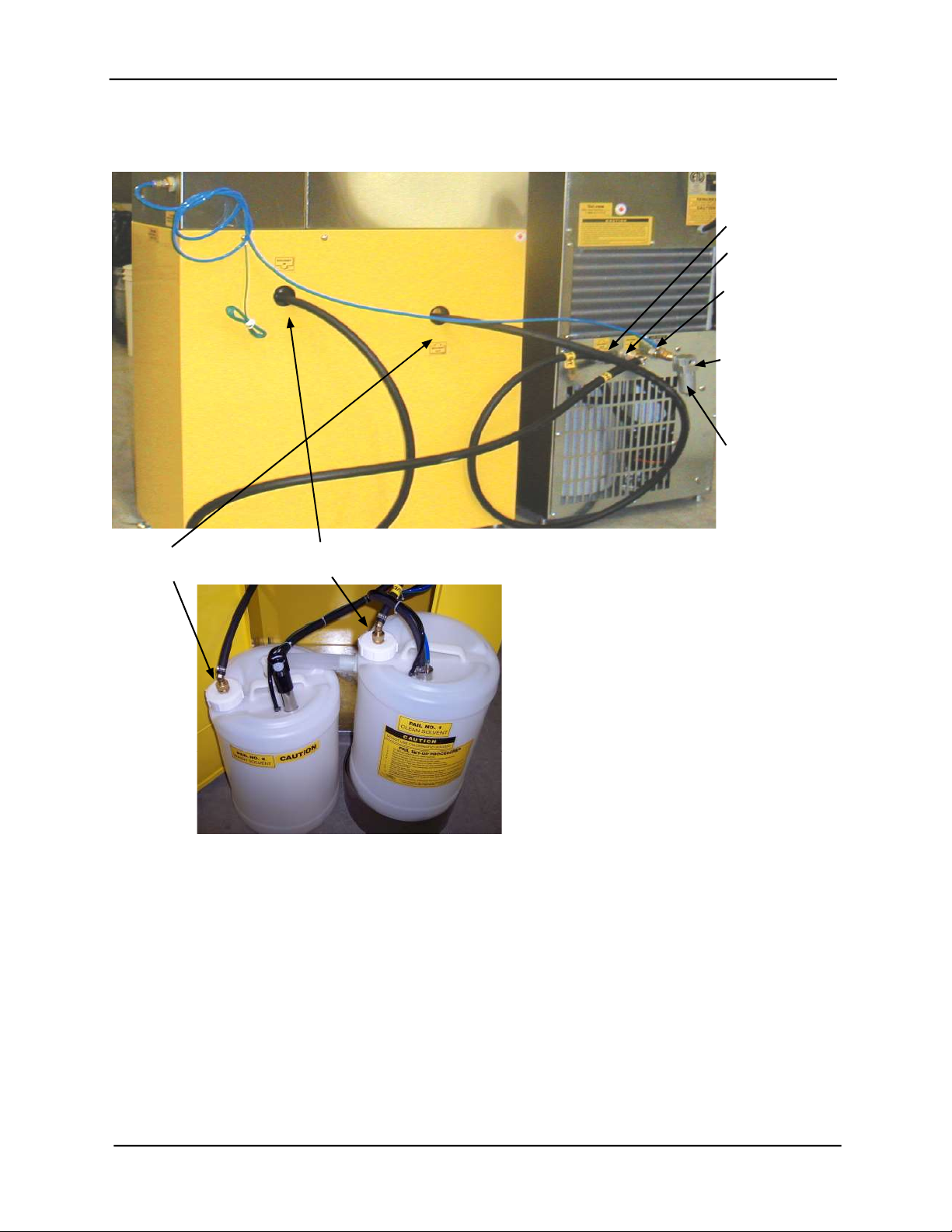
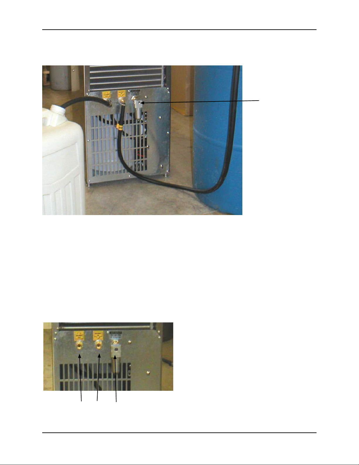
INSTALLATION OF SOLVENT TRANSFER HOSES AND THE AIR SUPPLY KIT (EP2 MODELS ONLY)
1) Transferring Solvent To and From a Spray Gun Cleaner
2) Transferring Solvent To and From a Drum / Container
3) Stand-alone Operation
For the URS500 and URS600 (Non-EP2) Models, use 3) Stand-alone Operation

7
MANUAL - SOLVENT RECYCLERS - URS500, 600, 500EP2, 600EP2 Revision 2019-07
Hoses:
Connect the end of the hose with the “Solvent
In” label to the “Solvent In” port on the recycler.
Hand tighten. Pass the other end of this hose
through the hole in the back of the gun cleaner
that is marked “Solvent Out” and hand tighten
onto the lid of the “WASH SOLVENT” pail. Con-
nect the hose with the “Solvent Out” label to the
“Solvent Out” port at the back of the recycler
and pass the other end of this hose through the
hole in the gun cleaner that is marked “Solvent
In” and hand tighten onto the lid of the “CLEAN
SOLVENT” pail. Make sure there is no leakage.
Air Supply:
The blue airline and Tee are for use with an
“E” series spray gun cleaner to allow one air
supply to feed both the spray gun cleaner and
the solvent recycler. Ensure the air supply is
not connected to the spray gun cleaner or
solvent recycler before installation.
Remove the 2 airline connectors from the “T” .
Connect the male port of the “T” to Air Inlet of
the recycler. Connect the Moisture Filter (op-
tional). Connect one end of the blue airline to
the “T”. Connect the other end of the blue air
line to the Air Input of the spray gun cleaner.
SOLVENT PAILS
Inside Gun Cleaner Cabinet
Dirty Solvent Out Clean Solvent In
1) Transferring Solvent To and From a Spray Gun Cleaner
Dirty Solvent In
Clean Solvent Out
Blue Airline - At-
tach to Tee and
Gun Cleaner
Air Supply Input,
Requires Fitting
(not supplied)
Attach Moisture Filter
(optional) to Air Input
and the Tee to the Filter
(if used) and the Blue
Airline to Tee and Gun
Cleaner. The Air Supply
fi tting is also not sup-
plied.

8
MANUAL - SOLVENT RECYCLERS - URS500, 600, 500EP2, 600EP2 Revision 2019-07
Connect the end of the hose with the “Solvent In” label to the “Solvent In” port on the recycler. Hand tight-
en. Connect the other end of the hose to the 3 ft suction pipe using the hose clamp. Insert the 3 ft suction
pipe into the drum / container of dirty solvent. Connect the other hose with the 4 3/8” suction pipe to the
“Solvent Out” port on the recycler and place the suction pipe into a clean drum / container large enough to
receive the clean, recycled solvent.
Air Supply:
The blue airline and Tee are for use with an “E” series spray gun cleaner to allow one air supply to feed
both the spray gun cleaner and the solvent recycler. It is not used in this situation. If necessary, connect a
Moisture Filter (not supplied) directly to the Air Input port of the Solvent Recycler and attach a suitable Air
Supply Fititing (not supplied).
2) Transferring Solvent To and From a Drum / Container
2) Stand-alone Operation
Not Used for Stand-Alone Operation,
no connections are necessary
Attach Air Supply
fi tting (not supplied)
and/or Moisture Filter
(not supplied)

9
MANUAL - SOLVENT RECYCLERS - URS500, 600, 500EP2, 600EP2 Revision 2019-07
OPERATING PROCEDURES
Wear protective clothing in accordance with local safety and environmental regulations. Use face goggles
and gloves as a minimum. Use an apron and respirator if required.
Summary of Operating Steps:
1) Open the Tank Lid and Safety Cover
2) Transfer Solvent to the Recycler Tank
3) Position Solvent Receiving Pail
4) Change temperature set point, as required
5) Start recycling
6) Finish Recycling
7) Transfer clean solvent
8) Remove debris
9) Clean Distillation Tank and Lid Surface
10) Install new liner bag
11) Inspect Lid Gasket, Remove and Replace if necessary
Each Step is described in detail below.
1) Open the Tank Lid and Safety Cover
• Open the safety cover.
• Open the inner lid by releasing the Lid Clamp.
• Make sure that Tank is empty and that a Liner Bag is properly installed in the Tank.
PULL UP TO OPEN. PUSH DOWN TO LOCK
LID CLAMP
TANK LID
2) Transfer Solvent TO the Recycler Tank
Verify that the solvent to be recycled complies with the requirements described in the section, Solvent
Requirements. Solvent can be put into the Distillation Tank by hand or by using the Transfer Hoses and
bulit-in Transfer System (EP2 Models only).
a) For models without the Solvent Transfer System
Pour the solvent into the Distillation Tank. Fill to 1.5 inches below the Retainer Ring.
Maximum volume is 5 gal (20 L) and minimum volume is 1.5 gal ( 6 L). Do not let the container of dirty
solvent touch the top of the recycler. When pouring the contaminated solvent, make sure all solvent goes
into the Liner Bag, not between the Liner Bag and Distillation Tank. Clean Lid Gasket and top of distilla-
tion tank. Close inner lid, engage lid clamp and close safety lid. Caution: Do not overfi ll Distillation Tank
because contaminated solvent could fl ow into Condenser and block the condenser passage way. Close
the Tank Lid, lock down the Lid Clamp and close the safety Cover.

10
MANUAL - SOLVENT RECYCLERS - URS500, 600, 500EP2, 600EP2 Revision 2019-07
b) For models with the Solvent Transfer System (EP2 Models):
• Open the Transfer Valve by turning the handle counter-clockwise 90°.
• Turn the Filling Timer knob clockwise fully. Dirty solvent will fl ow from the Transfer Port into the Liner
Bag and stop when the timer runs out.
• Close the Transfer Valve by turning the handle clockwise 90°.
• Close the tank Lid, lock down the Lid Clamp and close the safety Cover.
Transfer Valve
Filling Timer
Transfer Timer
Transfer Port
3) Position Solvent Receiving Pail
a) For models without the Solvent Transfer System
Open the Door and position a Solvent Receiving Pail (not provided) with a minimum size of
5 US Gal (20 L) inside the cabinet. Insert the Solvent Outlet Tube (short and curved) into the top opening
of the pail. The Solvent Outlet Tube must extend below the rim of the pail to prevent solvent spillage. If
the pail is metal, connect the alligator clamp of the Ground wire to the rim of the pail. Close the door.
b) For models with the Solvent Transfer System (EP2 Models):
Open the Door. A special, connected, plastic Solvent Receiving Pail is provided. Check to make sure that:
• the Solvent Outlet Tube is inserted into the hole in the top of the pail
• the Cap with the Pick Up Tube is tightly attached to the pail
• the Grounding Clamp (alligator type) is attched to the metal Pick Up Tube hose fi tting.
4) Change temperature set point, as required. If the Temperature Set Point is satisfactory, skip
this section.
Conditions to consider before starting Setup:
Minimize Temperature Set Point
After recycling there will be a small amount of solvent, about 1/8 US gal (500 ml), remaining in the distil-
lation tank due to condensation. Select the lowest Temperature Set Point that recycles the solvent to this
level.
Estimate Boiling Point
Add 45°C (113°F) to the boiling point of the pure solvent as shown on
the MSDS (Material Safety Data Sheet) or another reliable source.
Recycle more often
The boiling point of the waste solvent mixture increases as it gets dirtier. To reduce the boiling point,
recycle more often.
The display for the Control Panel is located at the top right corner of the base cabinet.
The LEDs for READY(L) and READY(H) on the control panel indicate the Temperature Set Point.
Lid Gasket

11
MANUAL - SOLVENT RECYCLERS - URS500, 600, 500EP2, 600EP2 Revision 2019-07
To Change the Temperature Set Point:
Make sure the “HEAT” and “FAN” lights are off . Press and hold the “OFF” button while pressing the “ON”
button repeatedly to cycle through the 6 possible Set Points. If you go past the desired Set Point, continue
to press the “ON” button until you cycle back to the missed Set Point.
TEMPERATURE SET
POINTS
READY LIGHTS
L M H
90°C (194°F) *
115°C (239°F) * *
140°C (284°F) *
165°C (329°F) * *
190°C (374°F) *
200°C (392°F) * * *
The Temperature Set Point is pre-set at the
factory to 200°C (392°F) - all 3 lights are on.
KEYPAD (CONTROL PANEL)
5) Start Recycling
Press “ON” button. Distillation starts, “HEAT” and “FAN” lights come on.
If you want to stop recycling press “OFF”.
6) Finish Recycling CAUTION: DO NOT OPEN LID UNTIL COOLING IS COMPLETE
The clean recycled solvent is available for use when the heat lamp goes off . Recycling is complete and
the unit is ready for the next operation when “HEAT” and “FAN” lights are off . Temperature set point indi-
cators - READY (L) and /or READY(H) lights are on but not fl ashing.
7) Transfer Clean Solvent
a) For models without the Solvent Transfer System: remove the pail and replace with an empty one.
b) For models with the Solvent Transfer System: turn the Transfer Timer knob clockwise fully. The clean
solvent will fl ow out of the Solvent Receiving Pail into either a free-standing, external container or the
Clean Solvent Pail of a Spray Gun Cleaner. The transfer will stop whwn the timer runs out.
8) Remove Debris:
Remove the Retainer Ring.
Slowly pull the Liner Bag containing the debris out of the distillation tank in a way that the Liner Bag does
not break.
Dispose of the debris in accordance with local regulations.
NOTE: If the bag sticks to the bottom of the tank, turn the recycler on for 5 minutes to loosen the bag from
the bottom of the tank, then lift the bag out while the bag is warm.
9) Clean Distillation Tank and Lid Surface
Distillation Tank:
Wipe and dry tank with a cloth.
Remove any remaining debris from the Distillation Tank using if necessary, plastic or wooden tools. Do
not clean with abrasive or hard metal instruments that can damage the tank. The warranty does not cover
such damage.

12
MANUAL - SOLVENT RECYCLERS - URS500, 600, 500EP2, 600EP2 Revision 2019-07
Note: There will be about 1/8 Gal (500 ml) of solvent remaining in the Distillation Tank after recycling due
to condensation. This solvent, If left in the tank, can cause corrosion. Dirt and debris left in the tank can
prevent full heat from reaching the dirty solvent during recycling.
Caution: Acidic or chlorinated solvents typically cause corrosion on an aluminum tank. It appears as
black pitting spots on the tank. Excessive pitting leads to an unsafe condition of holes in the walls of the
tank and solvent leakage. Inspect your tank after each batch. If there is excessive pitting, call a Service
Technician and replace the tank with a corrosive resistant, stainless steel one.
Lid Surface:
Use a cloth. Dry and clean the lid and the top of tank where the the Lid Gasket sits to extend the life of the
Lid Gasket and prevent leakage. Avoid rotating the lid during cleaning. The lid gasket is a wear item.
10) Install new Liner Bag
Lift Recycler Safety Cover and Tank Lid fully; lids will stay in the open position.
a) Install the Liner Bag so that the bottom of the Bag sits fl at on the bottom of the Distillation Tank as
shown.
b) With thumb and index fi nger, squeeze the Retainer Ring and insert into inside of the Liner Bag. Let go
and make sure it fi ts securely in the groove.
d) Fold the fl ap of the liner bag over the retainer ring so the fl ap is between the retainer ring and the wall
of the distillation tan. Caution: Ensure that the bag material does not block
the Vapor Outlet.
Do not reuse a liner bag. Use a new liner bag after each recycling for eff ective removal of waste.
11) Inspect Lid Gasket, Remove and Replace if necessary as required
Inspect the Lid Gasket for shrinking, hardness and cuts. The Lid Gasket is a wear item as it is exposed to
high temperature and solvent vapor during distillation. Damage to the lid gasket will cause solvent to leak.
To remove, open the Safety Cover and Tank Lid. Lift out the old gasket by hand and clean the cavity with
a cloth. To Install, place the new gasket in the cavity, rub solvent or soapy water on the gasket to make
insertion easier. Press the gasket fi rmly into the cavity all around.
Note: Keep a spare in stock. One extra is included with the unit.
NOTE: This is a schematic drawing only; not all components are exactly as shown.

13
MANUAL - SOLVENT RECYCLERS - URS500, 600, 500EP2, 600EP2 Revision 2019-07
THEORY OF OPERATION - DISTILLATION PROCESS
Waste solvent consists of the original solvent plus liquid and solid materials picked up during use of the
solvent. Recycling separates the original solvent from the waste materials. During the recycling process,
the distillation tank fi lls with dirty solvent and the heating element heats the mixture. The solvent mixture
boils and the vapour passes through a cooling condenser where purifi ed, clean solvent, ready for use
condenses out. Waste materials in the dirty solvent boil at a temperature substantially above the Tem-
perature Set Point so they remain in the distillation tank for disposal.
Solvent Recycling
Vapour Outlet tube
(vapor moves
to cooling condenser
from distillation tank)
Condenser
(cools vapor
to a liquid)
Receiving Pail
(contains clean,
recycled solvent)
Distillation
Tank
Heating Element

14
MANUAL - SOLVENT RECYCLERS - URS500, 600, 500EP2, 600EP2 Revision 2019-07
1. Maintenance
6W Remove the power supply or switch off the main switch before all
maintenance and service work.
Please note! Only use original spare parts for maintenance and repairs.
Ensure that the warning stickers present and the lights on the URS500 are clearly visible at all times so that they
can alert the URS500 users to safe use.
Please note! Never repair the URS500 yourself, use a recognized expert for this. Please contact your supplier. If
returning your URS500 device for repair, the boiler must be empty, otherwise your repair cannot be processed.
1.1. Periodic maintenance
Before each use:
• Keep the area around the URS500 clean and free of debris.
• Check the outside and inside of the URS500 for visible damage. Do not turn on the URS500 if you have
detected any damage.
• Check the lid gasket for damage. A damaged lid gasket leads to poor sealing and vapour leakage, which is
dangerous and wasteful.
• Inspect the cooling air outlet and inlet and ensure that there is sufficient space for unobstructed ventilation.
Vacuum clean, if necessary.
• Check the tank for residue and remove it.
• Wipe the top edge of the tank before closing the lid and make sure it is free from paint and contaminated
solvent.
Every month:
• Inspect the power cable for wear and damage. If replacement is necessary, the replacement should be
carried out by a competent installer for explosion proof equipment.
• Clean the condenser: refer to section 4.2 ‘cleaning the condenser’.
• Clean the cap of the condenser block. Refer to section 4.4 ‘Cleaning the condenser discharge tube” .
Every 3 months:
• Run two recycling processes with 5 gallons of clean solvent to keep the condenser discharge tube and the
condenser clean.
Every 6 months:
• Replace the lid gasket preventively.
WARNING

15
MANUAL - SOLVENT RECYCLERS - URS500, 600, 500EP2, 600EP2 Revision 2019-07
Condenser fins Cooling air outlet
Cooling air inlet
1.2. Cleaning the condenser
The condenser must be regularly checked and cleaned to ensure that it is free of dust and waste. Dust
and waste that has collected on the other side of the condenser is not visible in the URS500. If the
condenser overheats due to excessive dust, the process will stop and the LEDs will give the fault code 23
or 24. See section 4.6 "Error codes" of this manual for instructions when these errors are indicated.
To clean the condenser, the dust can be blown away with an air gun, or by using a vacuum cleaner with a
brush attachment.
1.3. Replacing the lid gasket
Please note! Always use original lid gaskets in the URS500.
To replace the lid gasket, follow these steps:
1. Open the safety cover and the tank lid.
Tank lid
Lid gasket
Figure 2. Tank lid of the URS500
2. Hold the lid open with one hand and remove the damaged lid gasket using a flat screwdriver.
3. Clean the edge of the lid where the lid gasket was with a scuff / abrasive material (non-woven), so
that all contamination is removed before the new lid gasket is introduced.

16
MANUAL - SOLVENT RECYCLERS - URS500, 600, 500EP2, 600EP2 Revision 2019-07
1. Install the new lid gasket by hand, by gradually pressing the ring all the way around with your fingers. It is
important that the ring is placed flat and no deformations are visible.
This can be checked by the horizontal seam on the ring, which must be straight along its entire length. Do
not use tools or sharp objects while installing the new lid gasket as they may damage the gasket.
You have replaced the lid gasket.
2. In order to check the proper functioning of the lid gasket, it is advised to recycle the tank once with ±10
litres of clean water.
1.1. Cleaning the condenser discharge tube
A blockage in the condenser discharge tube can cause solvent to leak out of the URS500.
1. Open the cap of the condenser block. This can be loosened by hand. If this doesn’t work, carefully use a
water pump pliers.
Condenser block
Cap from the
condenser block
Figure 1. The condenser block with cap
2. Check the condenser discharge tube and the opening of the vapour outlet for visible signs of blockage.
Condenser
block
Opening of the
vapour outlet
Figure 2. The condenser block

17
MANUAL - SOLVENT RECYCLERS - URS500, 600, 500EP2, 600EP2 Revision 2019-07
1. Clean the cap of the condenser block. It is important that all openings in the cap are free. If a layer of
lacquer / residue is blocking the openings, remove it with a small drill, or allow the cap to soak in thinner
and then scrape the dirt off with a metal pin.
Figure 1. Cap from the condenser block
2. If the blockage is not in one of these places, then the condenser is probably blocked.
3. Place a cloth over the inlet port located in the tank. The outlet tube is located inside the door above the
receiving pail. With a blow gun, blow air through the outlet port. Material in the condenser, if any, will exit
the inlet port in the tank.

18
MANUAL - SOLVENT RECYCLERS - URS500, 600, 500EP2, 600EP2 Revision 2019-07
PROBLEM CAUSE ACTION STEPS
Unit is plugged in, all the lights
on the Panel are Off .
Power is not getting to
the unit.
Reset breaker or replace fuse. If power is
still not getting to the unit, call a Qualifi ed
Service Technician. Ensure that the unit is
the only device on a circuit with suffi cient
capacity.
Unit is plugged in, “READY(L)” /
“READY(H)” lights are On, Heat
light fails to come on when “ON”
button is pressed.
Power board or fuse
not functioning.
Call Uni-ram Service
Recycled solvent is not clear 1) The solvent is react-
ing chemically.
1) Lower Termperature Set Point following
Operating Procedure 4.
2) The solvent fl ow
path is dirty. One
cause is overfi lling the
distillation tank.
2) To clean the path, follow Service Pro-
cedure 2 and then recycle 3 gal of clean
solvent.
3) Orange colour due
to rust in receiving
pail.
3) Place a jar under outlet tube and capture
some solvent. If the solvent is clear, replace
the pail with a non-corrosive one.
4) Milky colour due to
presence of water.
4) Eliminate source of water in solvent.
Dirty solvent remains in Dis-
tillation Tank after recycling
Note: 1/8 Gal (500 ml) of re-
cycled solvent is expected due to
condensation.
1) Poor heat transfer
due to dirt and debris
left in the tank.
1) Clean the tank, replace the Liner Bag,
recycle with pure solvent to test. If suc-
cessfull, the problem is due to a dirty tank,
debris left in the tank or the solvent is too
contaminated. Adjust accordingly. Follow
Operating Procedures closely. If the level
of contamination is too high, recycle more
often.
2) Boiling point of
solvent is above Tem-
perature Set Point.
2) Raise the Temperature Set Point and
repeat the recycling operation.The Tem-
perature Set Point should be the BP of pure
solvent (as determined from the MSDS or
other source) plus 45°C (113°F) to allow for
contamination. If the boiing point is above
the maximum Temperature Set Point for
your model (200°C), dirty solvent cannot be
recycled in this unit.
Liner Bag sticks Turn unit on for 5 mininutes and lift out bag
while it is still warm.
TROUBLE SHOOTING GUIDE
Carry out each action step until a solution is found. If the recommended actions do not solve the problem
call Uni-ram Service in North America or contact a qualifi ed Service Technician.
Caution: Disconnect the power supply before conducting maintenance or service.

19
MANUAL - SOLVENT RECYCLERS - URS500, 600, 500EP2, 600EP2 Revision 2019-07
PROBLEM CAUSE ACTION STEPS
Solvent vapor leaks from the Lid
Gasket
1) Lid Gasket has
excessive wear as
indicated by cracks,
shrinkage, hardness
etc
1) Replace the Lid Gasket (See Operating
Procedure 11).
2) Solvent fl ow path is
blocked.
2) Follow Service Procedure 2.
3) Lid Tension not
adequate
3) Follow Service Procedure 4.
3) The Lid is not
seated correctly.
3) Follow Service Procedure 5.
4) The temperature
SET-PT too high, re-
sulting in excessively
high solvent vapour
pressure
4) Reduce the Temperature Set Point and
repeat the recycling operation. If success-
ful, continue to recycle using the lower
Temperature Set Point.
Sections on Bag are brown and
thin due to High Temperature
1) Use of inferior low
temperature bag.
1) Use new genuine Uni-ram high tempera-
ture Liner Bag and recycle.
2) Temperature Set
Point is too high.
2) Reduce the Temperature Set Point and
repeat the recycling operation. If success-
ful, continue to recycle using the lower
Temperature Set Point.
The computer appears to be
operating erratically.
The computer may
require re-booting.
Disconnect the power supply for 30 sec-
onds. Restore power and operate unit.
Residue (puck) in Tank is too
wet.
1) Not enough heat to
vapourize the solvent.
1) Raise the Temperature Set Point
2) Residue cannot be
dried completely due
to its composition.
2) None.

20
MANUAL - SOLVENT RECYCLERS - URS500, 600, 500EP2, 600EP2 Revision 2019-07
ERROR CONDITION CODES
The computer constantly monitors the unit as it operates.
AN ERROR CONDITION IS INDICATED BY FLASHING “READY” LIGHTS.
NOTE: On later models of the URS500, due to a change in software, the heater light will fl ash dur-
ing normal operation. For all error conditions except for an error code “22” condition, the Heater light
would be off .
To determine the error type, count the fl ashes of READY (L ) before READY (H) fl ashes, then count the
number of fl ashes for READY (H ). For example, two fl ashes from READY (L) and then one by READY
(H) indicates error code 21. Look up the Error Code on the Chart below. Press the “OFF” button to stop
the error code and press the “ON” button to resume operation after the error condition has been correct-
ed. If the error persists, call for service.
ERROR
CODE
Flashing LED
Lights
Description Action Required
READY
(L)
READY
(H)
11 1 TIME 1 TIME Open circuit - defective tank
thermocouple
Contact Uni-Ram Service
12 1 TIME 2 TIMES Open circuit - defective condens-
er thermocouple
Contact Uni-Ram Service
13 1 TIME 3 TIMES Computer malfunction Replace computer circuit board
21 2 TIMES 1 TIME Open Heater Circuit - defective
component; heater element,
thermostat, wire conductor, blown
fuse. A defective thermostat or
wire terminal is the most likely
cause.
Contact Uni-Ram Service
22 2 TIMES 2 TIMES Defective heater triac; Heater is
still “ON”
Disconnect the power supply
immediately. Contact Uni-Ram
Service
23 2 TIMES 3 TIMES Condenser is overheating or ther-
mostat is faulty.
Clean dirty Condenser following
Service Procedure 1. If Ther-
mostat is faulty contact Uni-ram
Service
24 2 TIMES 4 TIMES If code 23 condition lasts over 10
minutes, this code will show and
operation is terminated.
1) Clean dirty Condenser. See
Service Procedure 1.
2) Position the unit to provide 6
inches (15cm) all around the unit.
3) Check Cooling Fan or Fan Mo-
tor.
31 3 TIMES 1 TIME a) Boiling did not occur within 45
minutes. Tank is either empty or
there is excessive debris in liner
bag or tank is dirty.
a) Clean Distillation Tank following
Operating Procedure 7, replace
liner bag, following Operating Pro-
cedure 9.
b) Set point is too low. b) Increase temperature set point
following Operating Procedure 4
and recycle with virgin solvent
c) Boiling point of solvent is
above maximim set point.
c) Solvent cannot be recycled.
This manual suits for next models
5
Table of contents