Unicla UWX550 Instruction sheet

UWX550 and UWX440
Installation Guidelines
®

Copyright ©2007
All rights reserved
No part of this document shall be reproduced in whole or in part without the permission of Unicla
International Ltd. This includes reproduction or copies in any form or by any means including
photocopying, printing or electronic media.
IMPORTANT DISCLAIMER
This is a guideline document containing professional information using representative graphs,
charts and tables. Manufacturers’ specications must be consulted for specic guidelines and
performance data. Unicla published data, specic to all models, is available in promotional literature
and from Unicla International Ltd on request or through your Unicla supplier.
Unicla International Ltd expressly disclaims all and any liability and responsibility to any person or
business as a result of any actions taken on the basis of information in this publication.
®
UWX550 and UWX440
Installation Guidelines
Table of contents
1 Initial handling ………………………………………………………………………… 2
2 System cleanliness …………………………………………………………………… 2
3 Fitting of discharge hose manifold ………………………………………………… 3
4 Mounting angles ……………………………………………………………………… 4
5 System oil quantity requirement …………………………………………………… 4
6 Oil type and grade …………………………………………………………………… 5
7 Compressor oil level ………………………………………………………………… 5
8 Compressor sight glass visualisation and diagnosis …………………………… 6
9 Recommended suction line pipe size …………………………………………… 7
10 Compressor speed …………………………………………………………………… 7
11 In-line suction lter and screen ……………………………………………………… 7
12 Oil injector ……………………………………………………………………………… 8
13 Discharge line analysis – pressure and temperature ……………………………… 8
14 Refrigerantcharging …………………………………………………………………… 9
15 Compressor operation analysis report …………………………………………… 10
Note: This booklet is designed to assist the installing technician to ensure Unicla
guidelines and procedures have been followed during the installation and initial
commissioning of UWX550 and UWX440 compressors.
Please read carefully and if further information is required please visit: www.unicla.hk
where a copy of the Unicla Compressor Fitting Guidelines to New Applications
booklet can be found, or contact the nearest Unicla dealer.
1.
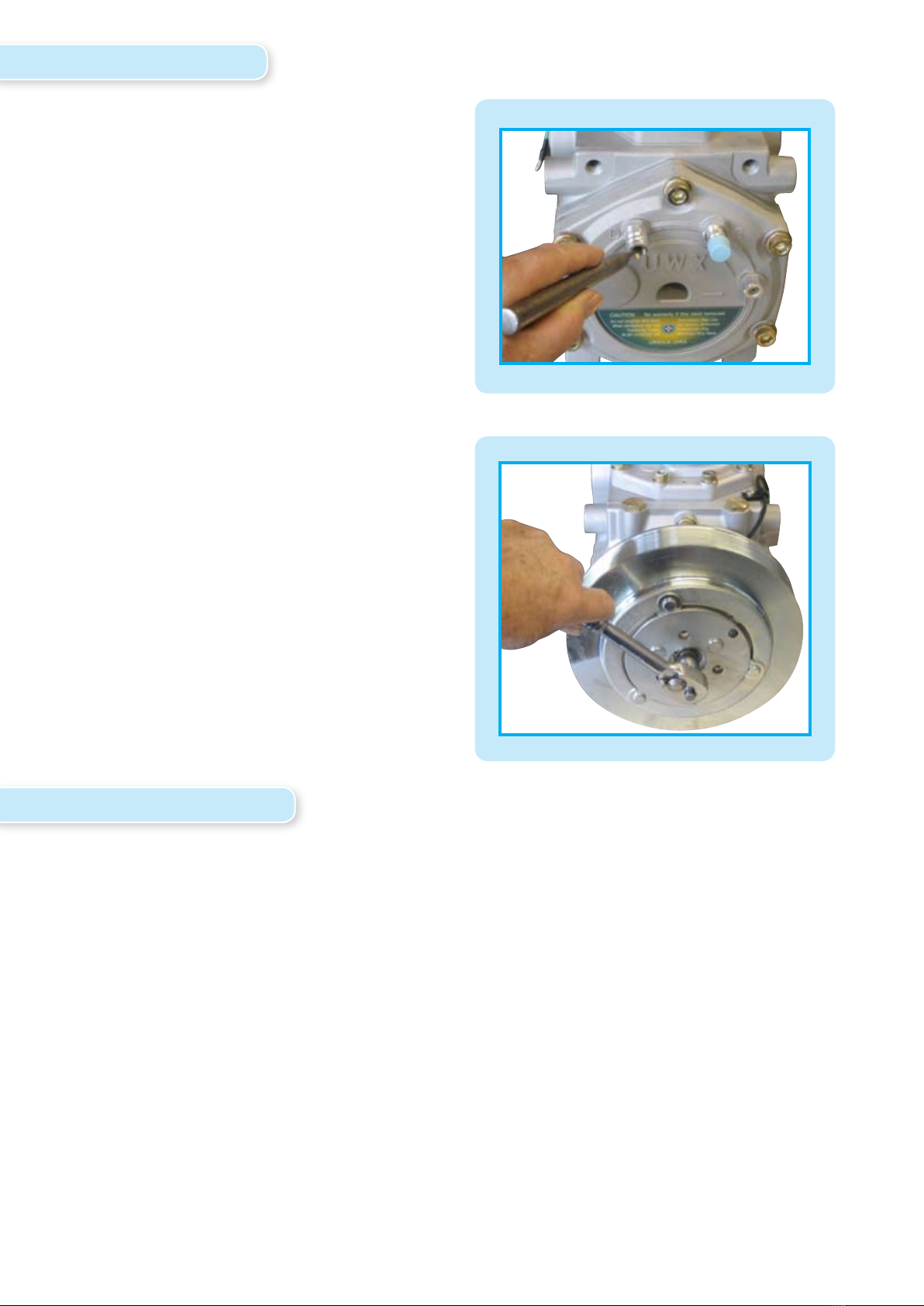
1. Initial Handling
a) Removing transit gas
Before mounting and when handling
a new Unicla UWX compressor for the
rst time, remove the dust cap from the
discharge service valve and gently release
the N2 gas as follows.
Take care to not let oil escape.
b) Initial lubrication
Rotate the compressor armature manually
for 4-5 revolutions to ensure proper
lubrication to the working assembly
components. This will avoid damage
during initial start up.
2. System Cleanliness
a) Contamination
The system must be free of both solid particle and chemical contamination before compressor
tting. Solid particle contamination will cause direct compressor damage and starvation due
to blocked system lters and screens (see section 10). Chemical contamination can reduce
solubility/miscibility of refrigerants and oils, reduce oil viscosity, and cause acid etching and
sludge formation.
b) Flushing
Contaminated systems must be ushed before tting the new compressor. Individual
component ushing is strongly recommended in systems where solid particle contamination
has occurred during the system assembly process. The compressor, TX valve, pressure control
valves, receiver driers/accumulators and muers/pulsation dampers must not be ushed.
2.
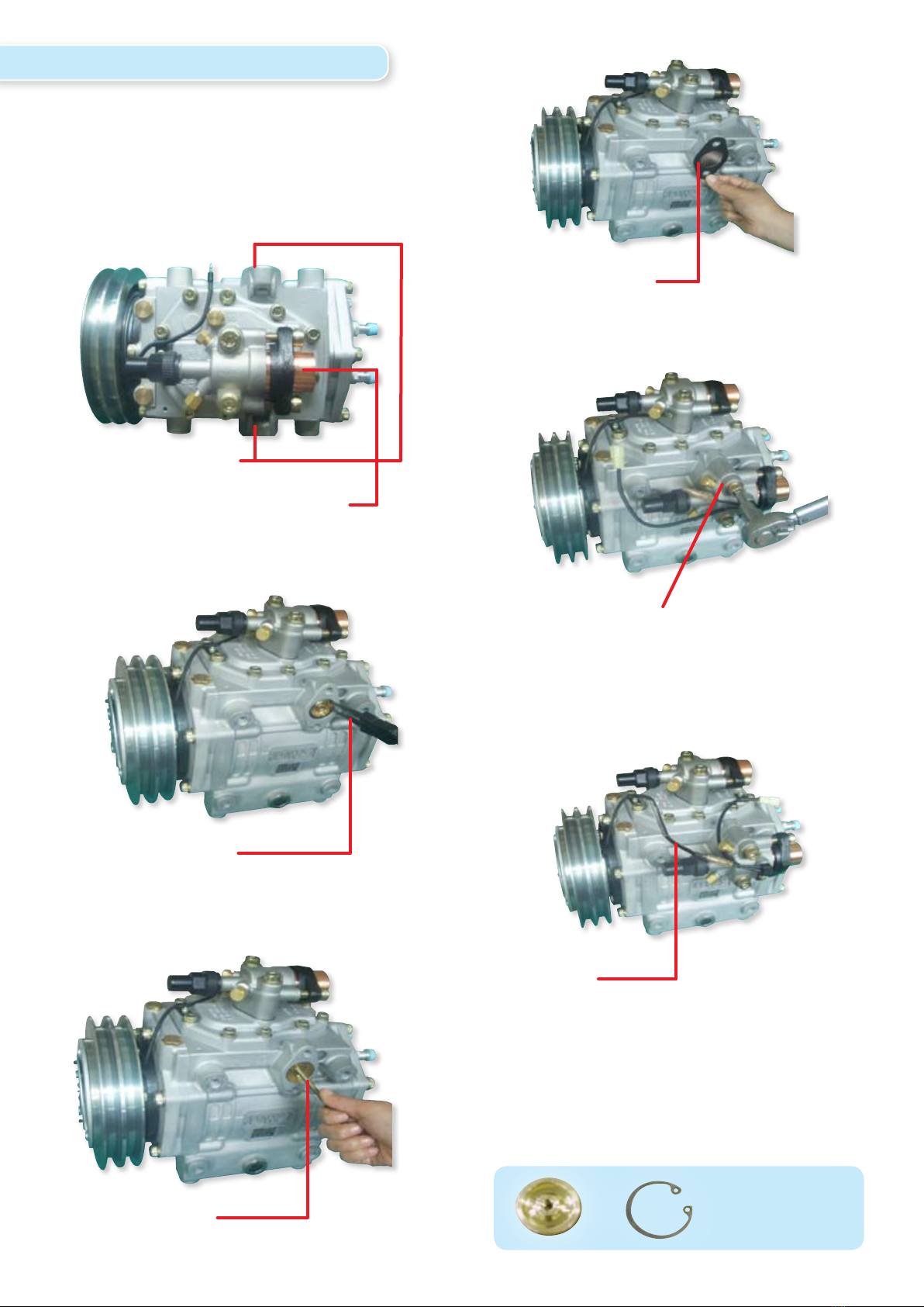
•Choose either left or right hand discharge port.
•Remove shipping cap from discharge port to be used.
Discharge Ports
Manifold Valve (Suction Port)
Snap-ring pliers
M6 x L65 Bolt
Install the bolt then pull out
Fig. A.
Fig. B.
Fig. C.
3. Fitting of discharge hose manifold
Install the gasket
Install Manifold Valve (this is right hand view)
M10 x L60 Bolt
Tightening tension 34.3 Nm (355 kg/cm)
Connect the clutch wire with the sensor from
Discharge Manifold Valve before operation
Warning: Do not directly connect power to
clutch wire.
Removed port
Fig. D.
Fig. E.
Fig. F
Clutch Wire
3.
For the compressor and system, Unicla compressor oil circulation requires that the correct amount of
oil must exist in the system to ensure oil and refrigerant ows back to the compressor in the correct
mixture ratio. To achieve this, the total oil quantity added to the system is as follows:
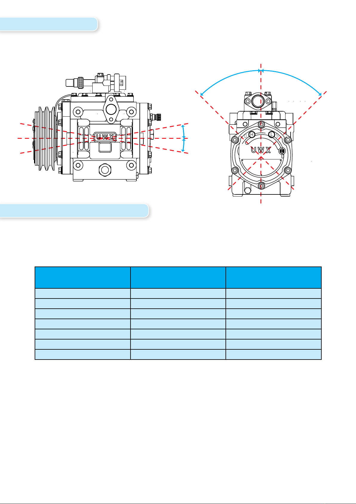
The limits for mounting Unicla UWX compressors are described in the following diagrams:
5. System oil quantity requirement
4. Mounting angle
Note: Oil quantity recommendations are in addition to the oil installed in the compressor. Unicla
440 and 550 series compressors are tted with 1000cc of oil as standard, and this amount is excluded
from the quantities recommend above.
Note: Oil quantity calculations are contained in the Unicla Service Handbook. Total system oil
requirement is based on 20% and 30 % of refrigerant charge for systems with < 6m suction line and
> 6m suction line respectively.
Larger capacity systems holding > 7.0 kg of refrigerant are deemed to require the maximum oil
quantity (30% of refrigerant charge) due to the potential size of the heat exchangers and hose runs
holding extra system oil.
Total Refrigerant in system Oil quantity to add –if suction
line < 6 metres in length
Oil quantity to add –if suction
line > 6 metres in length
5kg Nil 500cc
5.5kg 100cc 650cc
6.0kg 200cc 800cc
6.5kg 300cc 950cc
7.0kg 400cc 1100cc
7.5kg 1250cc 1250cc
8.0kg 1400cc 1400cc
within 10˚
within 10˚
within 45˚within 45˚
4.
700cc - 1000cc to top of sump (Normal)
400cc to top of sightglass (Low)
200cc to centre of sightglass (Low)
Compressor
Model
Refrigerant Oil Type
(Unicla)
Viscosity
@ 40˚C
Viscosity
@ 100˚C
Application Low side
Saturation
Oil
Separator
UWX R134a Unidap 7 48.01 10.51 Airconditioning > 0˚C Optional
UWX R134a Unidap 6 65.5 9.3 Airconditioning >0˚C Optional
Note: The correct amount and grade of oil must be
maintained in the compressor and the system. Failure
to comply with this may result in dramatically reduced
oil circulation rates with subsequent starvation of the
compressor.
!Warranty is void if these guidelines are not followed.
Unicla Oil Type Alternative
Unidap 6 POE 68
Unidap 7 PAG 46
Recommended alternatives for Unicla
Lubricant:
6. Oil type and grade
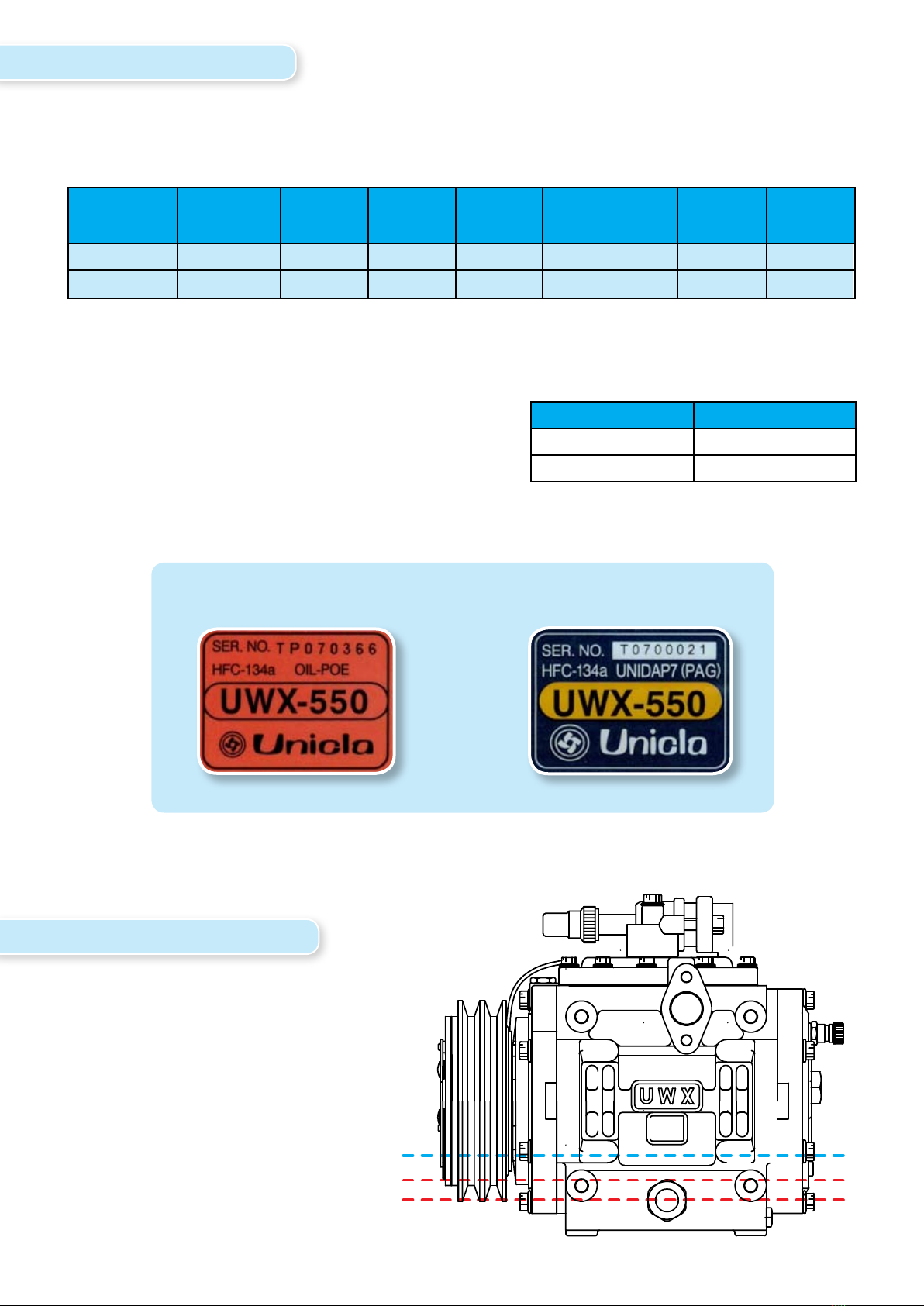
Each Unicla UWX550 or UWX440 is tted with either PAG oil ( Unidap 7) or POE oil (Unidap 6). When
adding oil to the system, Unicla oil must be used or alternatively if Unidap oil is not available at the
time of installation, then suitable known brand oil can be used as described in the following charts.
The following labels will determine the type of oil in each UWX
compressor:
7. Compressor oil level
Note: The following diagram
shows oil level quantities at the
sight glass to indicate actual oil
level in the sump.
POE type PAG type
5.

8. Compressor sight glass visualisation and diagnosis
The following chart and images will assist the technician to check the sight glass of the compressor
after commissioning of the system. Dierent operating conditions will present variable symptoms
to appear at the sight glass, and Unicla recommends this must be checked immediately after
commissioning and at future regular intervals during service.
To obtain the best possible visual of the sight glass, it is recommend the rear sight glass is back lit
with a good quality white light , preferably from a LED torch or leadlight. This will produce good
light through the centre of the compressor sump to allow accurate evaluation of the compressor
level and quality.
Sight Glass Normal > high point
Oil Normal - clean and transparent
Operation OK
Recommendation Nil
Sight Glass Normal > high point
Oil Slight moisture contamination - orange to brown colour
Operation OK
Recommendation Monitor oil condition and change if necessary
Sight Glass Normal > high point
Oil Green colouration - exposure to copper oxidation
Operation OK
Recommendation Monitor oil condition and change if necessary
Sight Glass Oil level low < half point
Oil Normal - clean and transparent
Operation Oil ow or level is low
Recommendation Check suction pressure and system oil quantity
Sight Glass Oil level low < half point
Oil Normal - clean and partly transparent
Operation Oil ow or level is low and running at high temperature
Recommendation Check suction pressure and system oil quantity
Sight Glass Normal > high point
Oil Black and cloudy - severely contaminated
Operation Compressor will fail
Recommendation Cease system operation - clean and ush system, replace compressor oil
Sight Glass Oil level < high point
Oil Black and cloudy - foaming and severely contaminated
Operation Compressor will fail
Recommendation Cease system operation - clean and ush system, replace compressor oil
Sight Glass Oil level < low point
Oil Not visible
Operation Oil ow or level is criticaly low - damage to compressor will occur. Suction
pressure is most likely at 1.0 bar (14 psi) or less and must be rectied
Recommendation
Cease system operation and check suction pressure and system oil quantity
6.
9. Recommended suction line pipe size
The following chart gives the suction pipe size recommendations for 440 and 550 compressors.
These recommendations must be strictly adhered to ensure adequate refrigerant and oil ow back
to the compressor. An undersized suction line will cause a pressure drop between the evaporator
outlet and the compressor, and create poor refrigerant and oil ow at the compressor. Particularly at
high revs and low evaporator temperatures.
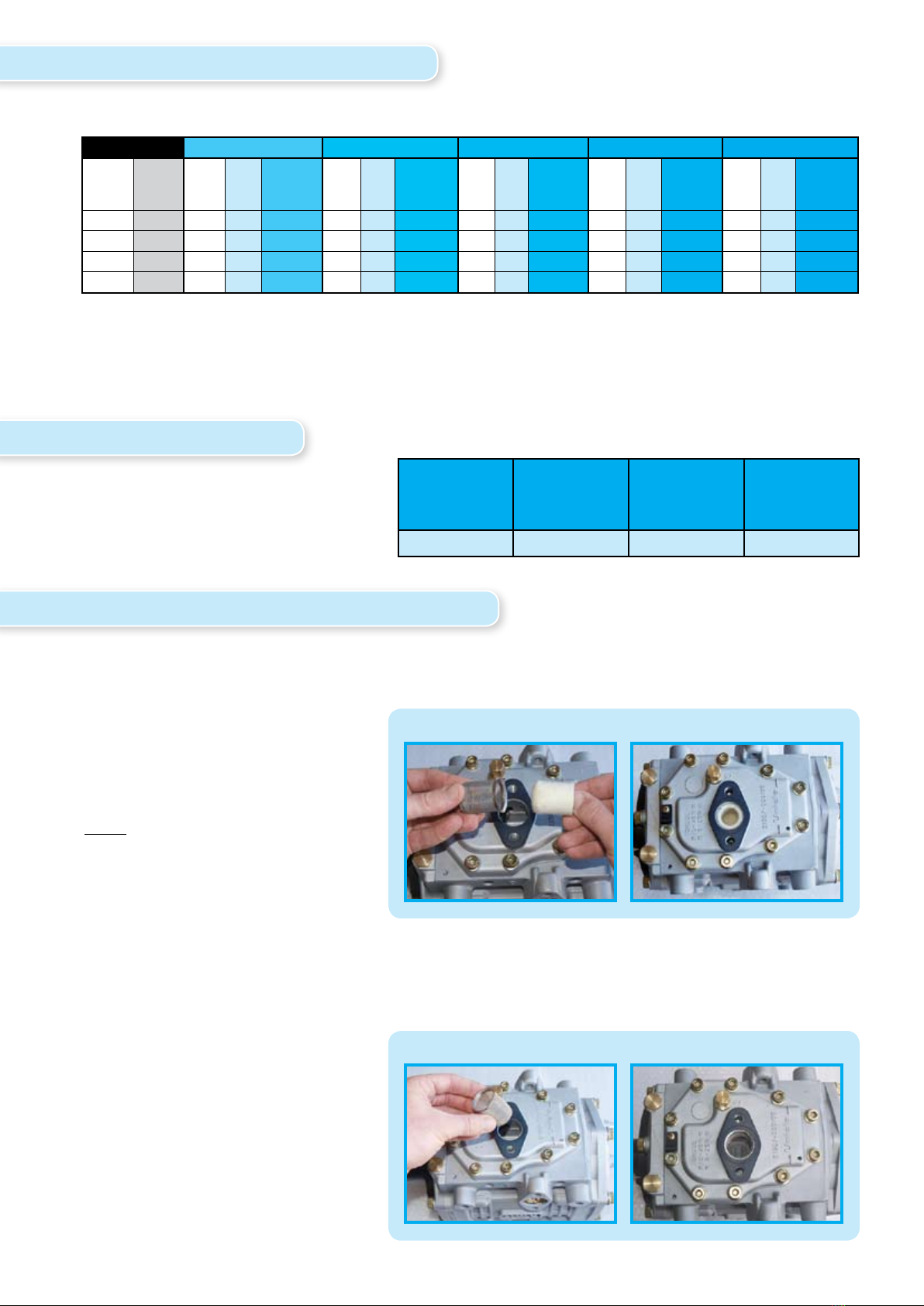
Unicla Suction Filter Insert
Part no: 43701-000290
Must be used in conjunction with
Unicla Suction Mesh Screen, and
must be removed after 2-12 hours
from initial commissioning. This is
ideal for removal of ne particles
from a new system.
Unicla Suction Mesh Screen
Part no: 43701-000270
Can be left in place in the suction
port to ensure continual removal
of heavier particles in the system,
however regular inspections of
this mesh screen must take place
to ensure a permanent blockage
does not occur.
10. Compressor speed
The following chart gives the Unicla
speed recommendation for UWX440
and UWX 550 compressors. This
should be strictly followed at all times.
11. In-line suction mesh screen and lter insert
The Unicla inline mesh screen and lter insert should be used whenever there is risk of debris and
ne particles entering the compressor through the suction line.
In the case of older systems where the compressor is replacing a previous failure, the system must be
ushed and the lter should be strictly monitored to ensure a blockage does not occur. More than
one lter maybe required over several hours to properly clean the particles in the suction line.
Rated Temp Press Pipe Size Temp Press Pipe Size Temp Press Pipe Size Temp Press Pipe Size Temp Press Pipe Size
RPM (kW) Di Di mm (inch) Di Di mm (inch) Di Di mm (inch) Di Di mm (inch) Di Di mm (inch
(K) (kpa) (K) (kpa) (K) (kpa) (K) (kpa) (K) (kpa)
1000 12.1 0.55 5.7 22 (7/8) 0.29 3 28 (1 1/8) 0.48 5 28 (1 1/8) 0.58 6 28 (1 1/8) 0.87 8.9 28 (1 1/8)
1500 18 029 3 28 (1 1/8) 0.58 6 28 (1 1/8) 0.98 10 28 (1 1/8) 0.41 4.2 35 (1 3/8) 0.61 6.3 35 (1 3/8)
2000 18 0.29 3 28 (1 1/8) 0.94 9.6 28 (1 1/8) 0.54 5.6 35 (1 3/8) 0.65 6.7 35 (1 3/8) 0.99 10.1 35 (1 3/8)
2500 26.7 0.64 6.5 28 (1 1/8) 0.44 4.5 35 (1 3/8) 0.74 7.6 35 (1 3/8) 0.89 9.1 35 (1 3/8) 0.56 5.7 41 (1 5/8)
Unicla 550 series
3m Pipe Length 6m Pipe Length 10m Pipe Length 12m Pipe Length 18m Pipe Length
Compressor
series
Ideal
operation
speed rpm
Maximum
continuous
rpm
Maximum
momentary
rpm
440/550 1200-2500 3000 4500
7.
Installation of mesh screen only
Installation of mesh screen and lter insert
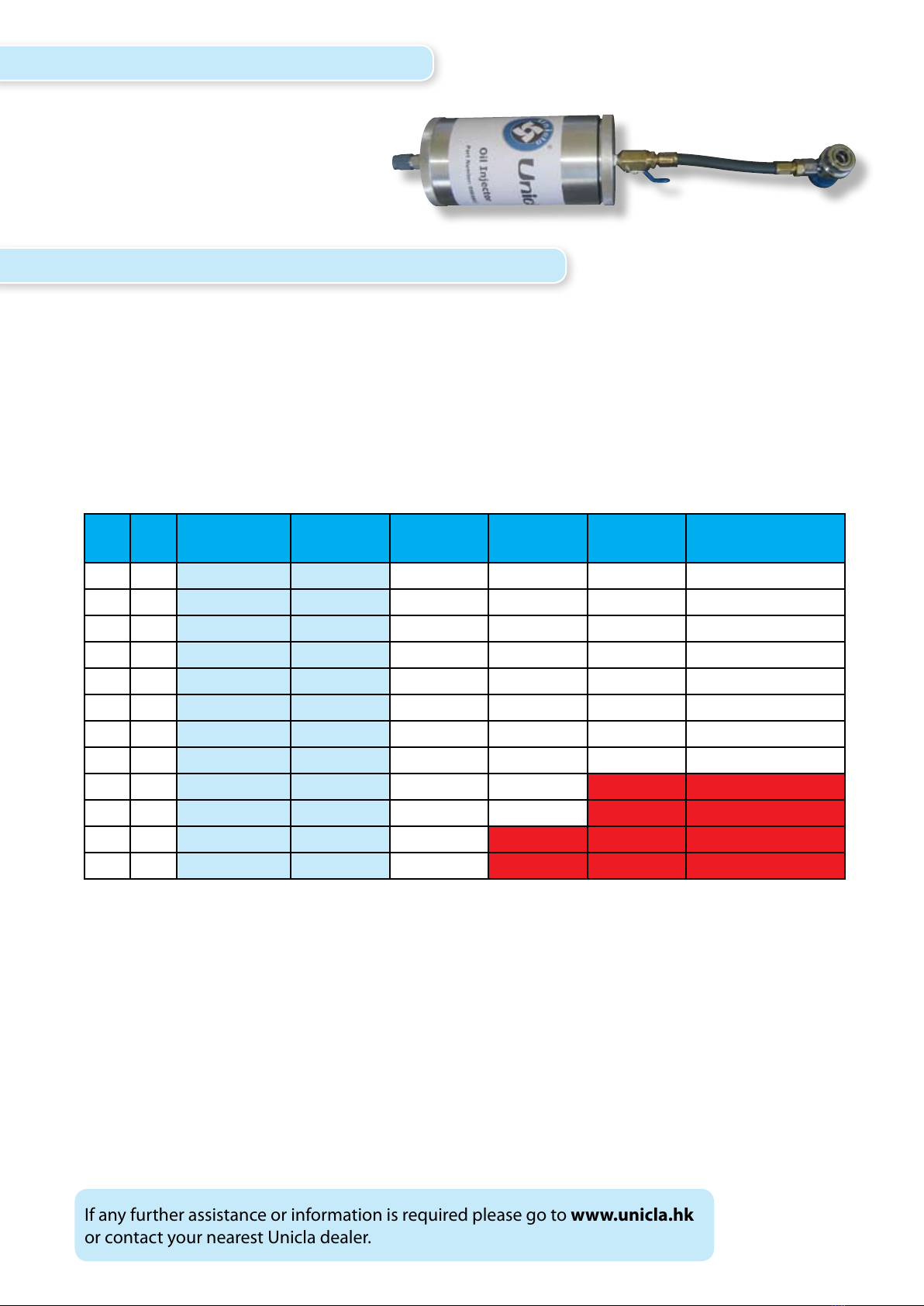
12. Unicla oil injector part no. OIRA803
Unicla oil injector can be used to
add additional system oil during the
evacuation or refrigerant charging
process. Or alternatively any similar
injection device can be used.
13. Discharge line analysis - pressure and temperature
After commissioning a Unicla compressor for the rst time, some basic pressure and thermal
loading checks will determine if the operating environment for the compressor is within Unicla
specications, and whether compressor durability is being maximised. The following chart should
be used as a guide for UWX550 and UWX440 compressors to analyse normally acceptable high
side (discharge/head) pressures and discharge line temperatures for given ambient conditions.
Discharge Line Pressure - Temperature Chart - Unicla UWX compressors
Ambient Ideal Discharge Pressure Discharge Line Temp ˚C Temp ˚C
Note: Allow 20% tolerance for humidity above 60% relative humidity.
If the system high side pressure or discharge line superheat range is not within these parameters,
reference to the Unicla Service Manual is required, or reference to additional technical information
for specications and faults regarding condensing to air dierentials.
• NR = not recommended as a continuous running phase, superheat may exceed 40°C, however
specic system design may allow for higher condensing capacity to maximise compressor
durability and performance.
• • NR = not recommended in most instances, superheat may exceed 50°C, however if condensing
capacity allows for < 50°C superheat, momentary running in this phase may be considered.
If any further assistance or information is required please go to www.unicla.hk
or contact your nearest Unicla dealer.
˚C ˚F kPa PSI 1800rpm 2200rpm 3500rpm Discharge line
Superheat range
15 60 600 - 800 90 - 115 37 - 42 42 - 47 50 - 56 7 - 26
18 65 750 - 950 110 - 135 43 - 52 47 - 58 56 - 70 9 - 34
21 70 900 - 1100 130 - 160 50 - 57 55 - 64 66 - 76 10 - 36
24 75 1050 - 1300 155 - 190 58 - 64 66 - 73 77 - 83 12 - 37
27 80 1200 - 1550 185 - 220 65 - 72 73 - 80 75 - 89 13 - 37
30 85 1400 - 1750 200 - 250 68 - 77 75 - 86 79 - 92 14 - 38
33 90 1500 - 1900 215 - 275 72 - 85 80 - 94 89 - 97 14 - 39
35 95 1700 - 2100 245 - 300 77 - 90 86 - 98 93 - 102 15 - 40
38 100 1850 - 2250 265 - 325 85 - 92 94 - 102 • NR 17 > 40
41 105 200 - 2400 290 - 350 88 - 97 97 - 108 • NR 18 > 40
44 110 2250 - 2650 325 - 385 92 - 102 • NR • • NR 18 > 50
47 115 2500 - 2900 370 - 420 102 - 110 • NR • •NR 20 > 50
8.
This manual suits for next models
1
Table of contents
Other Unicla Air Compressor manuals


