unicraft PG-I 8 SR User manual

Instruction Manual
Generator
PG-I 8 SR, PG-I 12 SR
PG-I 20 SR, PG-I 35 SE
PG-I 12 SR
PG-I 35 SE

2PG-I Series | Version 1.03
Imprint
Product identification
Generator Item number
PG-I 8 SR 6706108
PG-I 12 SR 6706112
PG-I 20 SR 6706120
PG-I 35 SE 6706135
Manufacturer
Stürmer Maschinen GmbH
Dr.-Robert-Pfleger-Str. 26
D-96103 Hallstadt
Fax: 0049 (0) 951 96555 - 55
E-Mail: [email protected]
Internet: www.unicraft.de
Indications regarding the operating instructions
Original instructions
Edition: 21.10.2020
Version: 1.03
Language: English
Author: FL
Indications regarding the copyright
Copyright © 2020 Stürmer Maschinen GmbH, Hallstadt,
Germany.
The contents of these operating instructions are the sole
property of the company Stürmer.
Passing on as well as copying of this document, the use
and distribution of its content are prohibited if not explic-
itly permitted. Contraventions are liable to compensa-
tion.
Subject to technical modifications and error.
Contents
1 Introduction ............................................. 3
1.1 Copyright ............................................................ 3
1.2 Customer service................................................ 3
1.3 Limitation of liability............................................. 3
2 Safety ....................................................... 3
2.1 Symbol explanation ............................................ 3
2.2 Obligations of the operating company ................ 4
2.3 Requirements to staff.......................................... 4
2.4 Personal protective equipment ........................... 5
2.5 General Safety Instructions ................................ 5
2.6 Safety labels on the generator............................ 6
3 Intended use............................................ 6
3.1 Predictable misuse ............................................. 6
4 Technical Data......................................... 6
4.1 Type plate........................................................... 7
5 Transport, packaging, storage............... 7
6 Device description .................................. 9
6.1 PG-I 8 SR, 12 SR and 20 SR ............................. 9
6.2 Device description PG-I 35 SE ......................... 10
6.3 Description of the control panels ...................... 10
7 Operating elements and functions...... 11
8 Commissioning ..................................... 13
8.1 Unpacking......................................................... 14
8.2 Check and fill in fuel.......................................... 14
8.3 Check and fill in engine oil ................................ 15
8.4 Ground generator ............................................. 15
8.5 Control lamp (PG-I 35 SE)................................ 15
8.6 Installation of the battery (PG-I 35 SE)............ 16
9 Operation ............................................... 16
9.1 Switch on the Generator................................... 16
9.2 Switching off the generator............................... 19
9.3 Workflow........................................................... 19
10 Connection of the consumers ........... 20
10.1 Power.............................................................. 20
10.2 Charging batteries .......................................... 20
10.3 Table of the consumer capacity...................... 21
11 Care, maintenance and repair............ 21
11.1 Care by cleaning............................................. 21
11.2 Maintenance and repair .................................. 22
11.3 Maintenance schedule.................................... 22
11.4 Oil change....................................................... 22
11.5 Clean oil filter.................................................. 23
11.6 Clean air filter.................................................. 23
11.7 Clean fuel filter................................................ 24
11.8 Spark plug maintenance................................. 24
11.9 Filter and spark protection .............................. 25
12 Disposal, recycling of used devices ...26
12.1 Decommissioning ........................................... 26
12.2 Disposal of lubricants...................................... 26
12.3 Disposal via municipal collection points.......... 26
13 Troubleshooting.................................. 27
14 Spare parts .......................................... 27
14.1 Ordering spare parts....................................... 27
14.2 Spare parts drawings...................................... 28
15 Electrical circuit diagrams ................. 62
15.1 Electrical circuit diagram PG-I 8 SR and 12 SR ...62
15.2 Electrical circuit diagram PG-I 20 SR ............ 63
15.3 Electrical circuit diagram PG-I 35 SE............. 64
16 EC - Declaration of Conformity.......... 65

Introduction
PG-I Series | Version 1.03 3
1 Introduction
You have made a good choice by purchasing the UNI-
CRAFT Generator
Read the operating manual thoroughly before com-
missioning the machine.
It gives you information about the proper commissioning,
intended use and safe and efficient operation and main-
tenance of your Generator
The operating manual is part of the Generator package.
Always keep this operating manual in the location where
your Generator is being operated. All local accident pre-
vention regulations and general safety instructions for
the operating range of your Generator must also be com-
plied with.
1.1 Copyright
The contents of these instructions are copyright. They
may be used in conjunction with the operation of the ge-
nerator. Any application beyond those described is not
permitted without the written approval of Stürmer Ma-
schinen GmbH. For the protection of our products, we
shall register trademark, patent and design rights, as this
is possible in individual cases. We strongly oppose any
infringement of our intellectual property.
1.2 Customer service
Please contact your dealer if you have questions con-
cerning your Generator or if you need technical advice.
They will help you with specialist information and expert
advice.
Germany:
Stürmer Maschinen GmbH
Dr.-Robert-Pfleger-Str. 26
D-96103 Hallstadt
Repair service:
Fax: 0049 (0) 951 96555-111
E-Mail: service@stuermer-maschinen.de
Internet: www.unicraft.de
Spare part orders:
Fax: 0049 (0) 951 96555-119
E-Mail: ersatzteile@stuermer-maschinen.de
We are always interested in valuable experience and
knowledge gained from using the application which then
could be shared and be valuable to develop our products
even further.
1.3 Limitation of liability
All information and notes in these operating instructions
were summarised while taking applicable standards and
rules, the state-of-the-art technology and our long-term
knowledge and experiences into consideration.
In the following cases the manufacturer is not liable for
damages:
- Non-observance of the operating instructions,
- Inappropriate use
- Use of untrained staff,
- unauthorised modifications
- technical changes,
- Use of not allowed spare parts.
The actual scope of delivery may deviate from the expla-
nations and presentations described here in case of spe-
cial models, when using additional ordering options or
due to latest technical modifications.
The obligations agreed in the delivery contract, the gen-
eral terms and conditions as well as the delivery condi-
tions of the manufacturer and the legal regulations at the
time of the conclusion of the contract are applicable.
2 Safety
This section provides an overview of all important safety
packages for the protection of the operating personnel
as well as for safe and fault-free operation. Other task
based safety notes are included in the paragraphs of the
individual phases of life.
2.1 Symbol explanation
Safety instructions
Safety instructions are marked by symbols in this ma-
nual. The safety instructions are introduced by signal
words which express the extent of the danger.
DANGER!
This combination of symbol and signal words indi-
cates an imminently dangerous situation which may
lead to death or severe injuries if they are not
avoided.
WARNING!
This combination of symbols and signal words indica-
tes a possibly dangerous situation which may lead to
death or severe injuries if they are not avoided.

4PG-I Series | Version 1.03
Safety
Tips and recommendation
It is necessary to observe the safety notes written in
these operating instructions in order to reduce the risk of
personal injuries and damages to property..
2.2 Obligations of the operating com-
pany
Of the operator
The operating company is the person who operates the
Generator for business or commercial reasons by her-
self, or leaves it to a third party for use or application, and
who bears the legal product responsibility for the protec-
tion of the user, the staff or for third parties.
Obligations of the operating company
If the generator is used for commercial purposes, the
operating company of the generator must comply with
the legal working safety regulations. Therefore, the
safety notes in this operating manual, as well as the
safety, accident prevention and environment protection
regulations applying for the area of application of the ge-
nerator must be met. The following applies in particular:
- The operator must inform himself about the appli-
cable occupational health and safety regulations
and determine additional hazards in a hazard as-
sessment which are caused by the special working
conditions at the place of use of the machine.
These must be implemented in the form of opera-
ting instructions for the operation of the machine.
- During the entire period of use of the machine, the
operator must check whether the operating instruc-
tions issued by him correspond to the current state
of the rules and regulations and, if necessary, ad-
apt them.
- The operator must clearly regulate and define the
responsibilities for installation, operation, trouble-
shooting, maintenance and cleaning.
- The operator must ensure that all persons handling
the machine have read and understood these in-
structions. In addition, he must train the personnel
at regular intervals and inform them about the dan-
gers.
- The operator must provide the personnel with the
necessary protective equipment and instruct them
to wear the required protective equipment in a bin-
ding manner.
Furthermore, the operator is responsible for ensuring
that the machine is always in perfect technical condition.
The following therefore applies:
- The operator must ensure that the maintenance in-
tervals described in these instructions are obser-
ved.
- The operator must have all safety devices regularly
checked for operability and completeness.
2.3 Requirements to staff
The different tasks described in this manual represent
different requirements to the qualification of the persons
entrusted with these tasks.
Only persons reliable working procedures can be expected
from, are allowed to perform all works. Persons the responsi-
veness of which is affected by e. g. drugs, alcohol or medica-
tion, are not allowed to work with the machine.
CAUTION!
This combination of symbol and signal words indi-
cates a possibly dangerous situation which may lead
to minor or light injuries if they are not avoided
ATTENTION!
This combination of symbol and signal words indi-
cates a possibly dangerous situation which may lead
to property and environmental damages if they are
not avoided.
NOTE!
This combination of symbol and signal words indica-
tes a possibly dangerous situation which may lead to
property and environmental damages if they are not
avoided.
Tips and recommendation
This symbol highlights useful tips and recommenda-
tion as well as information for all efficient and trouble-
free operation.
WARNING!
Danger in case of insufficient quali-
fication of the staff!
Insufficiently qualified persons cannot estimate the
risks while using the generator and expose themsel-
ves and others to the danger of severe or lethal inju-
ries.
- Have all works only performed by qualified persons.
- Keep insufficiently qualified persons out of the wor-
king area.

Safety
PG-I Series | Version 1.03 5
The qualifications of the personnel for the different tasks
are mentioned below:
Operator
The operator is instructed by the operating company
about the assigned tasks and possible risks in case of
improper behaviour. Any tasks which need to be perfor-
med beyond the operation if it is indicated in these in-
structions and if the operating company expressively
commissioned the operator.
Qualified personnel
Due to their professional training, knowledge and experi-
ence as well as their knowledge of relevant regulations
the specialist staff is able to perform the assigned tasks
and to recognise and avoid any possible dangers them-
selves.
Manufacturer
Certain works may only be performed by specialist per-
sonnel of the manufacturer. Other personnel is not au-
thorized to perform these works. Please contact our cus-
tomer service for the execution of all arising work.
2.4 Personal protective equipment
The personal protective equipment serves to protect per-
sons against impairments of safety and health while
working. The staff member has to wear personal protec-
tive equipment while performing different tasks on and
with the machine which are indicated in the individual
paragraphs of these instructions.
The personal protective equipment is explained in the
following paragraph:
2.5 General Safety Instructions
- Only operate the generator outdoors, sufficiently away
from windows, doors and fume cupboards.
- Never run the generator in closed rooms that are not
adequately ventilated. The engine produces carbon
monoxide and other noxious gases which are harmful
to the health of people who come into contact with
them. For this reason, adequate ventilation should be
ensured. Exhaust the combustion fumes from the per-
sonnel's working area via pipes and exhaust systems.
Install a CO alarm device!
- If the generator is to be used in rain or snow, adequate
protection and stability must be provided.
- Never touch the generator with wet hands.
- Do not connect the generator to public mains sockets.
- Ensure that the generator is earthed.
- Only operate the generator on horizontal surfaces to
ensure optimum flow of oil and fuel to the engine. If it is
not possible to operate the generator on horizontal
surfaces, the user must use suitable mounting and fi-
xing devices. Install levelling devices to ensure a safe
stand of the generator.
- Always keep children and unauthorized personnel
away from the running generator. Make sure that the
engine remains hot for about an hour when it is swit-
ched off. At the exhaust, exhaust pipes and engine the
increased temperatures last the longest. Touching
them can cause severe burns.
- Do not carry out any checks or maintenance on the ge-
nerator in operation; stop the engine in any case.
- Keep the generator at least 1 m away from buildings or
other equipment, otherwise the engine may overheat.
- Refueling with fuel and topping up oil must be carried
out with the engine switched off. It must be observed
that the engine maintains its high temperature for a pe-
riod of approx. 1 hour after switching off.
- Never refuel the generator while smoking or near a na-
ked flame.
- Make sure that no fuel is spilled on the engine or the
muffler when refuelling.
Hearing protection
Hearing protection helps to protect your hearing from
harmful noise and other loud noises.
Protective goggles
The protective goggles serve to protect the eyes
against parts flying off.
Protective gloves
The protective gloves serve to protect the hands
against sharp components as well as against fric-
tion, abrasions or deep injuries.
Safety boots
Safety boots protect the feet from being crushed, fall-
ing parts and slipping over on slippery ground
Protective clothes
Protective clothes are made of a tightly fitted fabric
without the protruding parts of low tear strength.

6PG-I Series | Version 1.03
Intended use
- The functions and circuits of the generator should be
known: Inexperienced persons should not be allowed
to use it.
- When the alternator is not in use, do not allow unautho-
rised persons to use it; therefore, fit the alternator with
blocking systems (remove the ignition key, lock the
protective cover with appropriate locks, etc.).
- Ensure that the working area is lit in accordance with
current standards.
- During operation, never place flammable materials
near the exhaust outlet.
- Do not remove any protective devices and do not run
the machine without suitable protection.
- If it is necessary to remove these guards (for main-
tenance or inspection), it is essential to stop the alter-
nator before doing so. This work must only be carried
out by qualified personnel.
- Never cover the generator with the protective cover and
switch it on.
- Do not run the machine in rooms with an explosive at-
mosphere.
- In case of emergency, do not use water to extinguish fi-
res, but only special safety systems (powder extinguis-
hers, etc.).
- If it is necessary to work next to the machine, the use of
hearing protection (headphones, ear muffs, etc.) is re-
quired.
2.6 Safety labels on the generator
The following safety labels and instructions are attached
to the generator (Fig. 1) and must be observed.
Fig. 1: Safety labels
The safety markings affixed to the machine must not be
removed. Damaged or missing safety markings can lead
to incorrect handling, personal injury and damage to pro-
perty. They must be replaced immediately.
If the safety markings are not visible and understandable
at first glance, the machine must be taken out of opera-
tion until new safety markings have been applied.
3 Intended use
The generator is exclusively for use as a power generator.
It is universally applicable for 230V consumers.
The generator may only be operated by persons who have
been instructed on the device.
Proper use also includes compliance with all the informa-
tion in these instructions. Any use beyond the intended use
or other use is considered misuse.
Stürmer Maschinen GmbH assumes no liability for design
and technical modifications to the generator.
Claims of any kind for damage due to improper use are ex-
cluded.
3.1 Predictable misuse
Misuse of the generator can lead to dangerous situati-
ons.
- Operation in rooms with fire or explosion hazard
- Outdoor operation in snow or rain.
- Refuelling during hot or running operation.
- Operation of the generator without the protective
devices provided.
- Bypassing or modifying the protective devices.
- Installation of spare parts and use of accessories
which are not approved by the manufacturer.
- Maintenance work on unsecured equipment.
4TechnicalData
DANGER!
Avoid direct physical contact with the fuel, engine oil
and battery acid. In case of skin contact, wash with
water and soap and rinse thoroughly: do not use
organic solvents. In case of eye contact, wash with
water and soap and rinse thoroughly. If these liquids
are inhaled or swallowed, consult a doctor.
Model PG-I 8 SR PG-I 12 SR
Length 395 mm 448 mm
Width / depth 209 mm 236 mm
Height 355 mm 392 mm
Net weight 9 kg 12,1 kg
Nominal voltage 230 V 230 V
Max. voltage de-
viation (+/-)
±3% ±3%
Limited output po-
wer (active power)
0,8 kW 1,1 kW
Continuous out-
put power (active
power)
0,7 kW 1 kW

Transport, packaging, storage
PG-I Series | Version 1.03 7
4.1 Type plate
Fig. 2: Type plate PG-I 35 SE
5 Transport, packaging, storage
Delivery
Check the generator after delivery for visible transport
damage. If you discover any damage to the generator,
report this immediately to the transport company or the
dealer.
Transport
Generator IP de-
gree of protection
IP 23M IP 23M
Socket type 1x230V,
DC12V,
4.0A
1x230V,
DC12V,
4.0A
Socket IP degree
of protection
IP54 IP54
Output max. drive
motor
0,9 kW 1,3 kW
Starter Hand launch Hand launch
Fuel Gasoline Gasoline
Tank capacity 2,1 Liter 3 Liter
Running time at
50% load
6,1 Std. 6,6 Std.
Running time at
100% load
4,1 Std. 4,4 Std.
Speed 3800-5000
rpm
3600-4800
rpm
Sound pressure
level
67 dB(A) 70 dB(A)
Weighted sound
power level (LWA)
93 dB(A) 93 dB(A)
Model PG-I 20 SR PG-I 35 SE
Length 525 mm 614 mm
Width / depth 282 mm 341 mm
Height 457 mm 506 mm
Net weight 18,5 kg 37,5 kg
Nominal voltage 230 V 230 V
Max. voltage de-
viation (+/-)
±3% ±3%
Limited output po-
wer (active power)
1,8 kW 3,1 kW
Continuous out-
put power (active
power)
1,7 kW 2,8 kW
Generator IP de-
gree of protection
IP 23M IP 23M
Socket type 2x 230V,
DC12V,
5.0A
2x 230V,
DC12V,
5.0A
Socket IP degree
of protection
IP54 IP54
Model PG-I 8 SR PG-I 12 SR
Output max. drive
motor
2 kW 4 kW
Starter Hand launch E-Start
Fuel Gasoline Gasoline
Tank capacity 4,1 Liter 7,5 Liter
Running time at
50% load
5,7 Std. 6,1 Std.
Running time at
100% load
3,8 Std. 4,1 Std.
Speed 3300-4500
rpm
3600-4800
rpm
Sound pressure
level
70 dB(A) 73 dB(A)
Weighted sound
power level (LWA)
93 dB(A) 96 dB(A)
CAUTION!
Injuries caused by parts falling over or off a forklift,
pallet truck or transport vehicle.
Only use means of transport that can carry the total
weight and are suitable for it.
Model PG-I 20 SR PG-I 35 SE

8PG-I Series | Version 1.03
Transport, packaging, storage
Improper transport of individual devices, unsecured de-
vices stacked on top of each other or next to each other
in packed or already unpacked condition is accident-
prone and can cause damage or malfunctions for which
we do not grant any liability or guarantee.
Transport the scope of delivery secured against shifting
or tilting with a sufficiently dimensioned industrial truck to
the installation site.
General risks during internal transport
Devices may only be transported by authorized and qua-
lified persons. Act responsibly during transport and al-
ways consider the consequences. Refrain from daring
and risky actions.
Gradients and descents (e.g. driveways, ramps and the
like) are particularly dangerous. If such passages are
unavoidable, special caution is required.
Before starting the transport check the transport route for
possible danger points, unevenness and disturbances
as well as for sufficient strength and load capacity.
Danger points, unevenness and disturbance points must
be inspected before transport. The removal of danger
spots, disturbances and unevenness at the time of trans-
port by other employees leads to considerable dangers.
Careful planning of internal transport is therefore essential.
The generator may only be transported in an upright posi-
tion. During transport, the generator must be well secured
so that it cannot tip over. The fuel must be drained.
Transport with a forklift/lift truck:
For transport with a sufficiently dimensioned lift truck or
forklift, the generator must be placed upright on a flat, so-
lid base (e.g. on a pallet) and secured against falling over.
Packaging
All packaging materials and packaging aids used for the
generator are recyclable and must always be sent for
material recycling.
Shredded cardboard packaging components should be
sent to the waste paper collection.
The films are made of polyethylene (PE), the padded
parts of polystyrene (PS). These materials are to be han-
ded in at a reusable material collection point or to your
local waste disposal company.
Storage
Store the generator thoroughly cleaned and in a vertical
position in a dry, clean and frost-free environment.
Generators must not be stacked on top of each other. Nor
may any other objects be placed on top of them.
If the generator is left unused for more than 30 days, it is
advisable to empty the fuel tank completely.
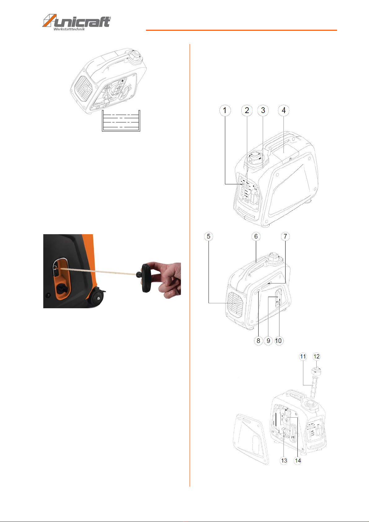
Step 1: Open the fuel filler cap.
Step 2: Place the collection tray under the drain plug.
Step 3: Tilt the generator slightly to empty the tank.
CAUTION: DANGER OF TIPPING!
The device may be lifted unsecured by a maximum
of 2cm.
Employees must be outside the danger zone, the
reach of loads. Warn employees and, if necessary,
advise employees of the hazard.
DANGER!
Only transport the generator with an empty fuel tank!
The plug connector must be disconnected.
NOTE!
Observe the weight of the machine during transport
and lifting work. The transport and lifting equipment
must be able to carry the load.
NOTE!
Protect the generator from moisture.
Tips and recommendations
For longer transports, make sure that the corrosion
protection is intact or is renewed if necessary.
DANGER!
The generator should be started at least every seven
days and run for about 30 minutes. If this is not pos-
sible and the generator is out of operation for more
than 30 days, appropriate measures should be taken
to ensure proper storage.
DANGER!
It is important to prevent deposits in the fuel system
(carburettor, fuel hose or tank) during storage. Fuels
containing alcohol (ethanol or methanol) can absorb
moisture, which leads to acid formation during sto-
rage. Acidic gases can damage the fuel system and
should be drained before storing for 30 days or lon-
ger. Never use engine or carburetor cleaning agents
in the fuel tank, this could cause permanent damage.

Device description
PG-I Series | Version 1.03 9
Fig. 3: Tilting the generator
Step 4: Open the drain valve to drain residual fuel from
the carburetor.
Step 5: Remove the spark plug and pour about one ta-
blespoon of SAE 10W30 or 20W40 engine oil
into the spark plug hole.
Step 6: Screw the spark plug back in.
Step 7: Let the engine turn several times with the pull
starter (with the ignition switched off).
Fig. 4: Pullstarter
Step 8: Clean the outside of the generator and apply a
rust protection.
6 Device description
Illustrations in this operating manual may differ from the
original.
6.1 PG-I 8 SR, 12 SR and 20 SR
Fig. 5: Description of PG-I 8 SR, 12 SR and 20 SR

10 PG-I Series | Version 1.03
Device description
1 Control panel
2 Consumer connections
3 Fuel tank
4 Spark plug
5 Exhaust pipe
6 Carrying handle
7 Choke
8 Fuel pump
9 Rope starter
10 Fuel tap
11 Fuel filter
12 Fuel filler cap
13 Oil filter cover
14 Air filter cover
6.2 Device description PG-I 35 SE
Fig. 6: Description of PG-I 35 SE
1 Fuel tank
2 Fuel filler cap
3 Fuel filter
4 Carrying handle
5 Exhaust pipe
6 Spark plug
7 Choke
8 Rope starter
9 Fuel tap
10 Brake
11 Wheel
12 Oil filter cover
13 Air filter
14 Fuel pump
6.3 Description of the control panels
6.3.1Control panel PG-I 8 SR
Fig. 7: Control panel PG-I 8 SR
1 Energy saving switch
2 Motor switches
3 Consumer connection 230V
4 Consumer connection 12V
5 Ground connection
6 DC circuit breaker
7 Indicator lights for oil, overload 12V and AC
12
3
5
4
6
7

Operating elements and functions
PG-I Series | Version 1.03 11
6.3.2Control panel PG-I 12 SR
Fig. 8: Control panel PG-I 12 SR
1 Energy saving switch
2 Motor switches
3 Indicator lights for oil, overload and AC
4 DC circuit breaker
5 Consumer connection 12 V
6 Ground connection
7 Consumer connection 230 V
6.3.3Control panel PG-I 20 SR
Fig. 9: Control panel PG-I 20 SR
1 Energy saving switch
2 Motor switches
3 DC circuit breaker
4 Consumer connection 12 V
5 Consumer connection 230 V
6 Ground connection
7 Consumer connection 230 V
8 Indicator lights for oil, overload and AC
6.3.4Control panel PG-I 35 SE
Fig. 10: Control panel PG-I 35 SE
1 Energy saving switch
2 Indicator lights for oil, overload and AC
3 consumer connection 230 V
4 Ground connection
5 Consumer connection 230 V
6 Electric starter, On / Off switch
7 Consumer connection 12 V
8 DC circuit breaker
7 Operating elements and func-
tions
Energy saving function
When the switch is in the "ON" position, the system con-
trols the motor speed according to the connected electri-
cal load. This improves fuel consumption and noise
emissions. When the switch is in the "OFF" position, the
engine speed remains constant.
12
3
6
7
5
4
12
3
4
75
6
8
NOTE!
The energy-saving switch must be set to "OFF" if
electrical loads are used that require a high starting
current, such as compressors, pumps or cooling
units.
12
3
6
8
7
54

12 PG-I Series | Version 1.03
Operating elements and functions
LED displays
The LED lights indicate the correct operation or a fault of
the generator
Control lamp AC (green):
The LED lights up as soon as the motor runs and gene-
rates voltage.
Overload indicator (red):
The LED lights up
- as soon as one of the connected consumers
consumes more current than the generator can
produce,
- if the control unit of the inverter heats up too much
- when the AC output voltage rises above the nomi-
nal value.
The (green) mains indicator light flickers while the red
LED of the overload indicator flashes. The motor swit-
ches off.
Take the following measures when the overload indica-
tor lights up:
Step 1: Switch off all connected electrical devices and
also the motor.
Step 2: Reduce the total power of the connected loads to
be below the nominal value.
Step 3: Remove any blockages in the cooling openings
and around the control unit; improve ventilation
or cooling if necessary.
Step 4: After having eliminated the causes of the over-
load, start the motor again.
Oil indicator light (red):
As soon as the engine oil level drops below the required
minimum level, this light switches on and the engine
stops automatically. The engine can only be restarted af-
ter the oil has been topped up and the correct level has
been reached.
ON/OFF switch for the motor
To start the generator, the switch must be set to "I". If the
switch is set to "O", the engine is stopped and cannot be
started.
DC circuit breaker
The DC protection switches off the unit automatically if
the load exceeds the generator nominal power.
Reduce the load to the specified nominal generator out-
put until the circuit breaker releases the unit.
Fig. 11: DC circuit breaker
Venting button Tank cap
The fuel cap is equipped with a vent button to stop the
flow of fuel. The bleed knob must be turned once clock-
wise from the closed position to operate the generator.
This allows fuel to flow to the carburetor and the engine
to run.
When the engine is not running, tighten the bleed knob
counterclockwise until it is finger tight to stop fuel flow.
Fig. 12: Venting tank cap
NOTE!
The overload indicator can also switch on for a few
seconds if electrical loads have been connected that
require a high starting current, such as compressors,
pumps or cooling units. In this case there is no fault.
NOTE!
If the oil lamp flashes when starting and the engine
does not start, oil must be topped up before a new
starting attempt is made.
Only operate the generator on level surfaces! An
uneven stand of the generator can lead to activation
of the engine oil protection.
DC circuit breaker

Commissioning
PG-I Series | Version 1.03 13
Fuel tap
The fuel tap controls the flow of fuel from the tank to the
carburettor. The knob of the cock must be in the "ON"
position to start and operate the generator. Set the fuel
tap to "OFF" when the engine is switched off and the ge-
nerator is stored or transported.
Fig. 13: Fuel tap
Choke
The choke is used during a cold start (when the engine is
cold). Use the lever to start the engine. After the engine
has warmed up sufficiently and stable operation has
been achieved, reset the choke. It is not necessary to
use the choke when starting an already warm engine.
Socket 230V AC
The socket can deliver a power continuously according
to the table of technical data.
Earth connection
Used to connect the generator to the mains earth
connection, if necessary. A qualified electrician must be
consulted regarding local regulations concerning the
earth connection.
8 Commissioning
NOTE!
The closed fuel tap prevents the carburettor from
'sinking' during storage and transport due to too
much fuel.
To use up the remaining fuel, turn the fuel tap to "O"
and leave the engine running until it switches itself off
after the remaining fuel has been used up.
Wear protective goggles!
Wear safety shoes!
Wear protective work clothing!
WARNING!
Danger to life!
There is danger to life if you do not follow these
rules.
- Never work with the generator if you are under the
influence of alcohol, drugs or medication and/or if
you are overtired or suffer from concentration disor-
ders.
- The generator may only be operated by one person.
Other persons must stay away from the generator
during operation.
CAUTION!
Risk of crushing!
There is a risk of injury to fingers and hands when
working improperly on the generator.
DANGER!
Before the generator is connected to the building's
power grid, a qualified electrician must install a circuit
breaker in the building's grid. This switch represents
the power supply point of the generator and allows
the choice of feeding the building with the generator
or the mains supply. In this way, charging of the main
grid (regenerative braking) by the generator is avoi-
ded, as this would lead to the risk of electric shock
and injury to the operating personnel.
In addition, the generator and the electrical system of
the building can be damaged if the generator is swit-
ched on without the circuit breaker.

14 PG-I Series | Version 1.03
Commissioning
8.1 Unpacking
Step 1: Place the carton on a stable and level surface.
Step 2: Remove the packaging from the generator.
Step 3: Check the generator and make sure that it has not
been damaged in transit. If any damage is found,
contact the service department or the dealer. In
this case, do not fill the generator with fuel or at-
tempt to start it.
8.2 Check and fill in fuel
The generator is supplied without fuel. Make sure that
enough fuel has been filled in before starting the generator.
Proceed as follows to top up fuel:
Step 1: Switch off the generator and disconnect the
consumer.
Step 2: Close fuel cock.
Step 3: Open fuel cap and check fuel level.
Fig. 14: Check filling level
Step 4: Clean the area around the tank filler neck.
Step 5: Fill the fuel tank with petrol. Use unleaded regular
gasoline with a minimum octane number of 85.
Step 6: Close the fuel cap.
Step 7: Wipe up spilled petrol!
DANGER!
Starting the engine with an insufficient oil level can
cause serious damage!
Check the fuel level:and use only clean and water-
free fuel.
The fuel is highly flammable and explosive under cer-
tain conditions. Refuel in a well ventilated area and
with the engine switched off. Do not smoke or use an
open fire while refuelling.
Never work with the generating set before the air fil-
ter has been inserted, otherwise the life of the engine
and the generating set will be reduced.
NOTE!
Before putting the generator into operation for the
first time, observe the following points.
- Make sure that the generator is placed on a flat, ho-
rizontal and stable surface.
- Check fuel and engine oil.
- Make sure that no power consumers are connected
to the generator.
- When starting the petrol engine, switch on the
choke for cold starting.
- To start generators with pullstarters, pull the starter
slowly out until resistance is felt, then pull jerkily.
CAUTION!
Do not fill the tank in enclosed spaces.
Never fill the tank while the machine is running or still
hot.
Do not overfill the tank (do not fill up to the top of the
filler), fuel could leak due to engine vibrations. Cau-
tion: Fuel expands when heated!
Ensure that no fuel drips to the ground during filling.
Ensure that the fuel filler cap is correctly closed after
refuelling. If petrol has dripped onto the ground,
ensure that the area is dry before starting the engine.
Avoid direct physical contact with the fuel and do not
inhale vapours; keep out of the reach of children.
The petrol vapours are flammable. Never light ciga-
rettes or smoke when refuelling. Avoid naked flames
at all costs.
Use normal unleaded, new and clean fuel, with a
minimum octane number of 85.
Never mix oil with fuel.
DANGER!
Never fill the tank while the engine is running! The
generator must cool down for at least 2 minutes
before opening the tank cap.
Open the fuel cap slowly to equalize pressure.
Never mix oil with petrol! Never overfill the fuel tank.
Leave space for the gasoline to expand. Regularly
check the pipes, tank and cap for leaks or damage.
Replace if necessary.
If the generator is operated at an altitude of more
than 1500 m above sea level, petrol with at least 85
octane must be used.
NOTE!
When using the generator for the first time, press the
pump button 6 times after refuelling with petrol.

Commissioning
PG-I Series | Version 1.03 15
8.3 Check and fill in engine oil
Make sure that the engine oil is at the upper level of the
oil filler opening. Add oil if necessary.
Top up the engine oil:
Step 1: Switch off the generator and disconnect the
consumer.
Step 2: Open and remove the side cover of the genera-
tor.
Step 3: Remove oil filler cap and check oil level.
Fig. 15: Check oil level
Step 4: Clean the area around the filling opening.
Step 5: If the oil level is below the lower level line, slowly
fill in oil until the required level is reached. Ne-
ver exceed the maximum fill level!
Select the suitable engine oil according to the tempera-
ture.
Recommended engine oil: SAE 10W30
Fig. 16: Engine oil as a function of temperature
Step 6: Check the oil level and screw the oil filler cap
back in.
Step 7: Refit the cover.
8.4 Ground generator
Step 1: Check that no power consumer is connected to
the generator.
Step 2: Check earthing. Proper grounding of the genera-
tor prevents electric shock in the generator or
connected electrical equipment. Proper
grounding also prevents static electricity,
which often builds up in ungrounded equip-
ment..
Fig. 17: Ground
8.5 Control lamp (PG-I 35 SE)
ON - The generator starts
OFF - The generator cannot be started
Fig. 18: Control lamp
High
Low

16 PG-I Series | Version 1.03
Operation
8.6 Installation of the battery (PG-I 35
SE)
Step 1: Switch off the generator and disconnect the
consumer.
Step 2: Remove the battery cover at the front of the ge-
nerator..
Fig. 19: Battery cover
Step 3: Connect the red wire to the positive (+) pole of
the battery.
Step 4: Connect the black wire to the negative (-) pole of
the battery.
Step 5: Insert battery and check that the battery is secu-
rely installed on the battery holder.
Recommended battery: 12V6AH
Step 6: Replace the battery cover.
9Operation
The engine is equipped with a low oil level sensor that
automatically stops the engine if the oil level drops below
a certain level. When the engine shuts off automatically
and the fuel tank contains enough petrol, the engine oil
level must be checked.
9.1 Switch on the Generator
9.1.1PG-I 8 SR, 12 SR and 20 SR
Step 1: Check oil and fuel and top up if necessary.
Step 2: Open the filler cap vent.
DANGER!
Make sure that the ECO switch is off when charging
the battery.
DANGER!
- No loads should be connected to the generator if
their electrical characteristics are unknown or if
their characteristics differ from those of the genera-
tor (e.g. different voltages and/or frequencies).
- The electrical circuit of the generator is protected by
a magneto-thermal switch, a magneto-thermal diffe-
rential switch or a thermal switch: possible over-
loads and/or short circuits will cause the circuit to
break. To reactivate the circuit, remove the excess
pantographs, find the cause of the short-circuit and/
or overload and reactivate the switch
- Do not place any objects on the frame or directly on
the engine when starting up the generator: any for-
eign bodies could affect its correct operation
- Do not obstruct the normal vibrations of the engine
alternator during operation.
- The ECO switch must be set to "OFF" when using
electrical equipment that requires a high starting
current, such as a compressor or submersible
pump.
- Make sure that the electrical appliance is switched
off before plugging it into the generator..
DANGER!
Never start or stop the engine when electrical
appliances are connected.
Disconnect all electrical appliances from the genera-
tor before starting.
Check that the generator is level.

Operation
PG-I Series | Version 1.03 17
Fig. 20: Venting tank cap
Step 3: Turn the knob for the fuel tap to "ON.
Fig. 21: Open fuel tap
Step 4: Turn the motor switch to the ON position.
Fig. 22: Operate motor switch
Step 5: Turn the knob for the fuel tap to "ON".
Step 6: When using the generators for the first time, after
refuelling with petrol, press the pump button 6
times.
Step 7: When the engine is cold: push the choke lever to
the "CHOKE" position.
Fig. 23: Actuate choke
Step 8: Slowly pull the pull starter until resistance is felt.
Then jerk the pull starter.
Fig. 24: Pullstarter
Step 9: Warm up the engine until it runs smoothly and
smoothly.
Step 10: Push the choke lever back to the "RUN" posi-
tion.
Fig. 25: Choke and run position
Engine
Switch

18 PG-I Series | Version 1.03
Operation
9.1.2PG-I 35 SR
Cable start
Step 1: Check oil and fuel and top up if necessary.
Step 2: Open the filler cap vent.
Fig. 26: Venting tank cap
Step 3: Turn the knob for the fuel tap to "ON".
Fig. 27: Open fuel tap
Step 4: Turn the motor switch to the "ON" or "RUN" posi-
tion
Fig. 28: Operate motor switch
Step 5: Turn the choke lever to the "CHOKE" position
Fig. 29: Actuate choke
Step 7: Slowly pull the pull starter until resistance is felt.
Then jerk the pull starter.
Fig. 30: Pullstarter
Step 8: Warm up the engine until it runs smooth and
round.
Step 9: Push the choke lever back to the "RUN" position.
Fig. 31: Actuate choke
Electrical start
Step 1: Open the tank cap vent.
DANGER!
Never start or stop the engine when electrical
appliances are connected.
Disconnect all electrical appliances from the genera-
tor before starting.
Check that the generator is level.
Engine
switch
Engine
switch

Operation
PG-I Series | Version 1.03 19
Fig. 32: Venting tank cap
Step 2: Turn the knob for the fuel tap to "ON".
Fig. 33: Open fuel tap
Step 3: Turn the choke lever to the "CHOKE" position
Fig. 34: Actuate choke
Step 4: Turn motor switch to "START" and "RUN" posi-
tion.
Fig. 35: Operate motor switch
Step 5: Run the engine warm without load until it runs
smoothly and smoothly.
Step 6: Push the choke lever back to the "RUN" position.
Fig. 36: Actuate choke
9.2 Switching off the generator
Step 1: Switch off or interrupt all consumers supplied by
the generator.
Step 2: Disconnect the mains plug of the electrical
consumers from the generator.
Step 3: Run the motor for 2-3 minutes without load, then
set the energy saving switch and the motor
switch to "O" or "Off".
Step 4: Turn the fuel tap or tank ventilation to "O" or
"Off".
9.3 Workflow
Step 1: Let the engine warm up for a few minutes.
Step 2: Add up the power (watts or amperes) of the
electrical consumers. The sum must not ex-
ceed the capacity of the generator or fuse.
Step 3: Plug in the electrical consumer(s). The consu-
mers must be switched off.
Step 4: Switch on the electrical consumer(s).
Engine
switch
Engine
switch
DANGER!
Even after the engine has been switched off, it still
emits heat, so adequate ventilation should be provi-
ded even after the generator has been switched off.
DANGER!
If the connected loads overheat, switch them off and
disconnect them from the generator.

20 PG-I Series | Version 1.03
Connection of the consumers
10 Connection of the consumers
10.1Power
Calculation of the power in watts required for starting and
operating the loads to be supplied.
Step 1: Select the electrical loads to be used at the same
time.
Step 2: Calculate the total power of these consumers in
watts. This value corresponds to the power re-
quired to keep the loads in operation.
Watt = Volt x Ampere
Step 3: Locate the consumer with the highest starting
current value and add this value to the previously
calculated values.
Step 4: Start the motor without the consumers connected
and let it run for a few minutes so that it can sta-
bilise.
Step 5: Connect and switch on the first consumer, prefer-
ably the consumer with the highest power requi-
rement first. Then wait until the motor has stabili-
zed.
Step 6: Connect the next consumer, switch it on and wait
until the motor has stabilized, etc.
10.2Charging batteries
Start the engine and wait until it has reached the correct
speed before connecting the battery. The batteries can
be charged via the 12 V DC socket.
Step 1: Make sure that the energy saving switch is set to
"O" or "Off" while charging the batteries.
Step 2: Make sure that the red cable of the battery char-
ger is connected to the positive (+) pole of the
battery and the black cable is connected to the
negative (-) pole of the battery. Never mix up
these two cables!
Step 3: Firmly connect the battery charger's pole termi-
nals to the battery's poles so that they cannot
become loose due to vibration or other stres-
ses.
Step 4: Charge the battery according to the instructions
in the battery user manual.
Refer to the battery operating manual for information on
charging times.
DANGER!
The generator should be started at least every seven
days and run for about 30 minutes. If this is not pos-
sible and the generator is out of operation for more
than 30 days, the following measures should be
taken to ensure proper storage:
Empty the fuel tank, start the generator and let it run
until all fuel is used up and the generator stops.
Cover the cooled generator and protect it from
moisture.
Further measures in the chapter "Storage".
ATTENTION!
Ensure that the nominal voltage and frequency of the
generator are compatible with all electrical loads that
the equipment must supply. If the current consump-
tion exceeds the generator power, one or more loads
must be disconnected and connected to a separate
generator.
The DC sockets may only be used for charging 12 V
batteries.
Never connect three-phase consumers to the gene-
rator.
Never overload the generator.
NOTE!
The starting current is an extra pulse of power requi-
red to start some electrical consumers. If you follow
the steps described in the following section, the
consumers are started one after the other.
NOTE!
The DC circuit breaker automatically switches to "O"
when the current exceeds the rated value.
To restart the charging process, set the DC circuit
breaker to "I" or "On".
CAUTION!
Never start or stop the generator while electrical
loads are connected or switched on.
This manual suits for next models
3
Table of contents
Other unicraft Portable Generator manuals