FORCE 50
REV. 2.2 2021-02-04
3-2
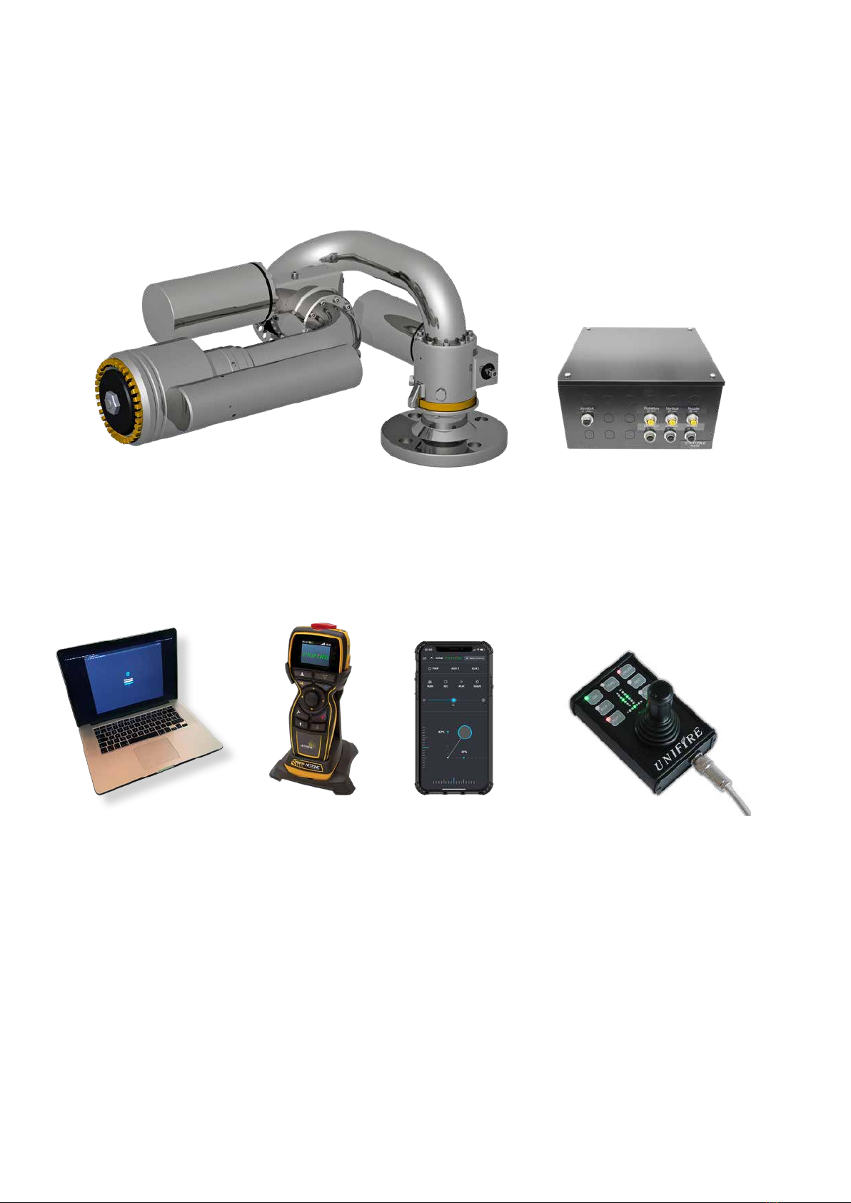
UNIFIRE FORCE 50 Robotic Nozzle
Installation and setup manual
PLANNING
PLANNING - BEFORE INSTALLATION
About This Manual
This manual is a comprehensive guide that contains the
information necessary to design, install, operate, and
maintain the FORCE 50 Robotic Nozzle system.
Users of this manual are assumed to be competent fire
engineers with a basic knowledge of such systems. Users
who are not familiar with the equipment should first read the
complete manual.
Only certified personal who have undergone UNIFIRE AB
training are allowed to install this equipment.
Contacts
Should any part of this manual not be understood, or there
are queries concerning the system, contact UNIFIRE AB
Technical Support using the following details:
UNIFIRE AB,
Bultgatan 40B
442 40 KUNGÄLV
SWEDEN
www.unifire.com
APPROVALS AND STANDARDS
See Section 2 System Components for approval and listing
information for the various components.
SAFETY warnings
A properly designed and installed FORCE 50 Robotic
Nozzle should not present any significant health or safety
problems. Take basic precautions to avoid accidents. The
various aspects of the system’s operation must be under-
stood. Observe best practices.
Do not operate this device without a full understanding and
comprehension of this manual. Personnel responsible for
the FORCE 50 system must be fully trained on the system
components.
The installer should pay specific attention to the danger,
caution, warning, and notice statements in this manual.
Failure to observe safety warnings could cause serious
injury, and potentially create liability.
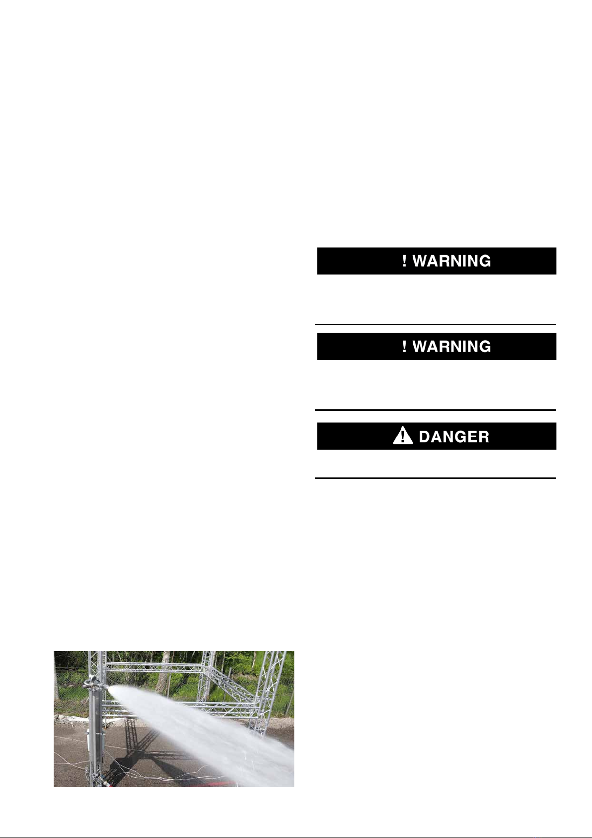
Do not direct the flow stream towards people as it could
result in serious personal injury or death.
• Operate and maintain the FORCE 50 Robotic Nozzle
system in compliance with this document and with appli-
cable standards, in addition to the standards of any other
authorities having jurisdiction (AHJ). Failure to do so
impairs the proper operation and integrity of this device.
• The owner must maintain the fire protection unit or system
and devices in proper operating conditions.
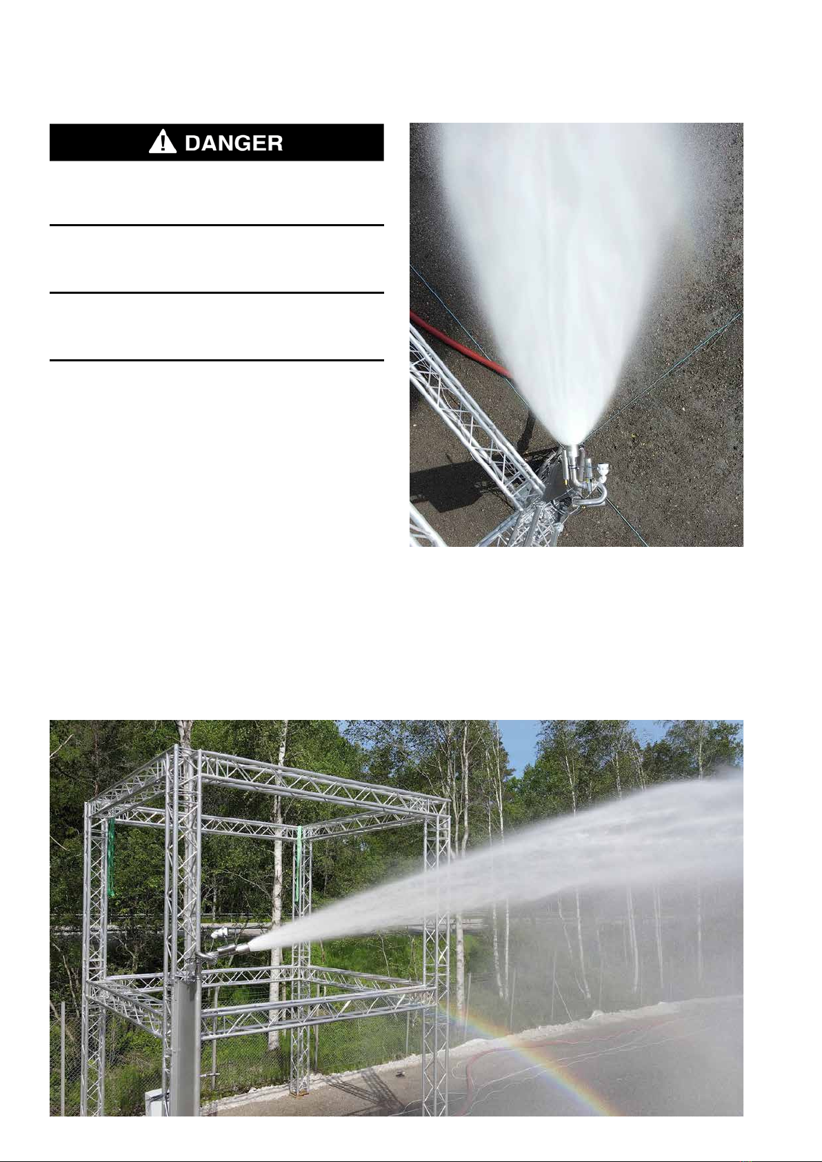
• Do not, under any circumstance, operate this system
outside the water flow or pressure range indicated in this
manual.
• The owner must ensure that an uninterrupted supply of
water is maintained to the Robotic Nozzle.
Authorized Personnel
The FORCE 50 system shall be installed by
authorized personnel certified by UNIFIRE AB. Use compo-
nents and accessories authorized only by UNIFIRE AB.
Structural Alterations
This installation manual details the suggested installation
method. Any structural alteration necessary for installation
must comply with local building code requirements.