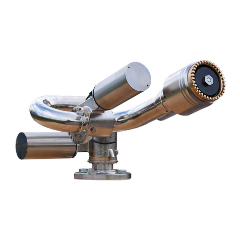
Unifire FORCE 80 User guide

!
1
FORCE 80
BLCD with TARGA Robotic Nozzle PLC
Generic system manual
FORCE50 BLDC and the TARGA Robotic Nozzle PLC
rev 1511
page 1(24)

Robotic Nozzle
Robotic Nozzle PLC
Welcome to the world of Unifire! And congratulations on your purchase of the
world’s most advanced, stainless steel, remote control robotic nozzle system.
This professional equipment should only be used by qualified and trained
professionals who have read and understood this manual. So please read this
manual before installing and operating your new FORCE 80. It will familiarize you
with the dangers associated with operation, as well as provide proper installation
and operation instructions.
NOTE: EVERY SYSTEM HAS CUSTOMER SPECIFIC CONFIGURATION. ALSO READ
THE DOCUMENT PROVIDED WITH YOUR ORDER# DESCRIBING YOUR SYSTEM.
Unifire AB’s warranty, and term and condition of sales are available for download at
www.unifire.com!
2
rev 1511
page 2(24)

TECHNICAL SPECIFICATIONS FORCE 80 BLDC
The UNIFIRE FORCE 80 is a marine specification, stainless steel foam and water
robotic nozzle. The finish is manually polished stainless steel, providing a long
service life of fantastic look with minimum maintenance.
It features M12 multi-connectors on all connection points for simple installation
and maintenance.
The optional Canbus Joystick has a one-step record and playback feature, valve
control and position indication LED’s.
The UNIFIRE FORCE Robotic nozzle is the most advanced, highest quality and
best performing system available in the market today.
FORCE 80 Specification:
Weight 30 Kg (FORCE 80 with INTEG80 nozzle)
Dimensions 75x48x35 cm (approximately)
Pipe dimension 80mm inside Ø
Power 24-30 V DC max 12 A
Range of motion +/-90° vert , 360° rot
Speed (of high speed version) 12°/sec rotation , 8°/ sec vertical
Progressive speed control over joystick
Material Body 316L Stainless Steel
Gear bronze
Nickel plated connectors (option)
Gold-plated pins (option)
Max Flow up to 5500 lit/min at 12 bar
Max Reach up to 90 m at 12 bar
Reaction force Up to 5000 N
Mechanical installation Support must withstand 20000 N of force
Connection 3” male BSP or DN 80/100 flange
Pipe dimensions for installation Min 100 mm
Pump requirement
for maximum performance 5500 lpm @ 12 bar
Communication Canbus (Unican) 125 or 250 kbps. "
Interface for Canopen, profibus, modbus, etc.
Option digital inputs for up/down/left/right/jet"
spray
Options Various network options, Canbus, TCP/IP Network,
Web-server, radio remote Joystick, etc.!
3
rev 1511
page 3(24)

TABLE OF CONTENTS
INSTALLATION FORCE 80 Chassis 9
General Information & Warnings 9
Spare parts specification!
10
Joystick “PI” 13
Adjusting the flow of INTEG80 14
Flow chart of the FORCE 80 with INTEG 80 15
Reach chart of FORCE 80 with INTEG80 16
Operating the Joystick 17
MAINTENANCE of the FORCE 80 with BLDC motors 19
MAINTENANCE of the INTEG 80 with BLDC motors 20
Canbus JOYSTICK Description & Advanced Setup 21
(this section also applies to the Wireless PI Joysticks) 21
Joystick Buttons and LED Function Description 21
Setting baud rate, Master-slave mode and Canbus ID 22
Setup mode “A” 23
Setup mode ”B” 24
4
rev 1511
page 4(24)

READ THIS INSTRUCTION MANUAL IN ITS ENTIRETY PRIOR TO
INSTALLING, MAINTAINING, OR USING THE UNIFIRE FORCE™
ROBOTIC NOZZLE (AKA ”ROBOTIC NOZZLE” OR “CANNON”).
Failure by any installer, maintenance personnel or operator to receive
proper training, including reading and understanding this manual, prior
to its use constitutes misuse of the equipment and could result in
serious bodily injury or death and/or damage to the robotic nozzle or
other property. Only qualified and trained professionals who are familiar
with this equipment and general safety procedures may operate the
Force robotic nozzle.
The purpose of this Manual is to provide all users, installers, and
maintenance personnel with the relevant information concerning the
design, proper use, installation and maintenance of the equipment and
should be read and made available to all such persons. This Manual will
help prevent danger and injury to you and others. If you would like
further copies of this manual, ask Unifire or download it at
www.unifire.com. If you have any questions relating to this equipment
and its safe use please contact Unifire prior to use at +46 303 248 400.
DO NOT ATTEMPT TO MODIFY THIS EQUIPMENT IN ANY WAY.
Modification of the equipment may result in damage to, or malfunction
of, the equipment, which could lead to serious injury of the operator
and/or others. Internal inspection, maintenance and repairs should only
be performed by, or under the specific, express authority of Unifire AB.
NEVER POINT THE FORCE 80 OR ANY Robotic nozzle DIRECTLY
AT HUMANS WHILE WATER IS SPRAYING THROUGH IT, as doing
so can result in serious injury or possibly death. The FORCE 80 is
capable of directing flows of up to approximately 5500 liters per minute
(1300 gallons per minute) at pressures of up to 12 bars (175 psi) and
has a maximum throwing range of up to approximately 90 meters (95
yards). Such forces are very dangerous and capable of producing
serious injury or death to persons and serious damage to
property. They are also capable of throwing objects with extreme force
and velocity into other objects or persons. Accordingly, only
professional, trained firefighters or other qualified individuals may
operate this equipment after being thoroughly familiar with the Manual,
and always by exercising extreme caution to avoid hitting people or lose
objects with the water (or other fluid) stream.
!
!
!
!
!
!
5
rev 1511
page 5(24)

BE SURE THAT THE ROBOTIC NOZZLE IS TIGHTLY AND
PROPERLY SECURED AT ALL TIMES DURING OPERATION! Serious
injury or death can occur if the robotic nozzle is not fully and properly
secured and supported. Be sure that the mounting pipe for the FORCE
80 robotic nozzle is capable of withstanding a nozzle reaction force of
at least twenty thousand (20,000) Newtons (2000 kgf). The
FORCE 80 robotic nozzle should not be used on a portable stand of any
kind, as such use can be extremely dangerous and can result in Serious
Injury or Death.
THE FORCE 80 IS HEAVY. USE CAUTION AND ASSISTANCE WHEN
INSTALLING AND TAKE CARE TO AVOID INJURY TO YOUR BACK.
Seek assistance to help support and twist the robotic nozzle during
installation and take care to avoid injury to your back during handling
and installation.
NEVER USE THE ROBOTIC NOZZLE AT PRESSURES HIGHER THAN
12 BARS (175 PSI). The maximum operating pressure for the FORCE
80 robotic nozzle is 12 bars (175 psi). Use of the FORCE 80 at
pressures higher than 12 bars is dangerous and can lead to serious
injury or death or may damage the robotic nozzle. Moreover, the
recommended operating pressure of the FORCE 80 is between 7
and 10 bars (100 and 130 psi), which also will provide optimal
performance.
ONLY MOUNT THE FORCE 80 SO THAT ITS BASE IS
PERPENDICULAR TO THE GROUND. DO NOT install the robotic
nozzle at an angle or upside-down without the specific prior written
consent of Unifire AB. Doing so may cause damage to the robotic nozzle
gears and motors, which could lead to malfunction.
FOLLOW ALL MAINTENANCE & INSPECTION PROCEDURES in this
manual.
BE SURE TO USE THE PROPER TYPE AND SIZE OF THREADS AT
THE ROBOTTIC NOZZLE BASE and also between the robotic nozzle
and nozzle (if using a nozzle not supplied by Unifire specifically for use
with this robotic nozzle). Use of the wrong type or size of threads will
result in an improper connection which can cause leaking and also may
cause the robotic nozzle and/or nozzle to dislodge under high pressure,
possibly leading to serious injury or death to persons and/or serious
damage to property. If you have any doubts as to the exact thread
supplied by Unifire, contact Unifire for clarification prior to connecting
the robotic nozzle and nozzle.
!
!
!
!
!
!
!
!
!
!
!
!
6
rev 1511
page 6(24)

KEEP A SAFE DISTANCE DURING OPERATION AND MOVEMENT.
The FORCE 80 robotic nozzle has moving parts. Be sure to keep a safe
distance from the robotic nozzle as it moves and keep hands and fingers
away from pinch points to avoid injury.
AVOID RAPID CHARGING. Rapid charging of the robotic nozzle is
potentially dangerous and can cause serious injury to persons and/or
property and may cause damage to the robotic nozzle. Charge the
robotic nozzle slowly to avoid creating a potentially dangerous, high-
pressure surge.
USE ONLY UNIFIRE-APPROVED NOZZLES. The FORCE 80 was
designed for use with the Unifire INTEG 80 and Unifire Smooth Bore
nozzles. Use of any nozzle other than a Unifire nozzle made for the
FORCE 80 without specific, written approval in advance by Unifire AB
constitutes misuse of the product and could affect the safety,
performance and/or operation of the robotic nozzle. Such malfunctions
could also result in the nozzle coming loose and being rapidly ejected
with high force, which could cause serious injury or even death.
DO NOT OPERATE IN EXPLOSIVE ZONES OR ENVIRONMENTS! The
electric motors and other components are potential ignition sources and
could spark ignition if used in explosive environments. The FORCE 80 is
not approved for operation in explosive environments and therefore it
should never be used in such environments.
DO NOT IMMERSE EQUIPMENT IN WATER. Do not immerse the
robotic nozzle, its control box (the TARGA PLC) nor the joystick in water
and be sure to keep water out of their interiors. Unifire’s robotic
nozzles, and joystick are designed to withstand moderate exposure to
rain and water splashing during normal use of the robotic nozzle.
Prolonged or extreme exposure to water, including submersion,
however, will cause damage and could also cause electrical shock
resulting in injury.
The TARGA PLC must be installed protected form water and dust. IP67
rated enclosure is optional.
Do not use the electrical controls during operation of the
emergency manual override cranks as doing so could cause injury.
!
!
!
!
!
!
!
!
!
!
!
!
7
rev 1511
page 7(24)

ONLY USE THE MANUAL OVERRIDE IN CASE OF TRUE
EMERGENCY & POWER FAILURE. The manual override controls on
the FORCE 80 are not designed for normal operation and should only be
used in the case of extreme emergency and when the remote control
feature is not working sufficiently to control the robotic nozzle by means
of the electronic controls. In case of use in such an emergency,
first disconnect the cables from the motor connections. !!
DISCONNECT POWER PRIOR TO INSTALLATION, MAINTENANCE
OR REPAIR. Prior to installation, maintenance or repair be sure to
disconnect power and disable flow.
ONLY USE SPECIFIED ELECTRICAL SUPPLY, INSTALLED BY A
QUALIFIED ELECTRICIAN. The power supply to the TARGA ROBOTIC
NOZZLE PLC should be supplied through high-quality cables and fuses
with proper power overload protection. Electrical overload can cause
damage to the TARGA PLC and other electrical components, leading to
failure of the robotic nozzle. Be sure that the electrical power supply to
the robotic nozzle is connected through proper wires and fuses and
installed or approved by a qualified electrician.
DO NOT MOUNT ANY DEVICES ON THE ROBOTIC NOZZLE.
Mounting peripheral devices on the Robotic nozzle is not recommended
and can cause undue wear and tear, possibly leading to damage to the
gears welds, etc. Use of peripherals on the robotic nozzle will void
warranty claims unless specifically approved in advance and in writing
by Unifire AB.
FAILURE TO HEED ANY WARNING IN THIS MANUAL VOIDS
WARRANTY CLAIMS & MAY CAUSE SERIOUS INJURY TO
PERSONS OR PROPERTY.
!
!
!
!
!
!
!
!
!
!
8
rev 1511
page 8(24)

INSTALLATION FORCE 80 Chassis
General Information & Warnings
BE SURE TO USE THE PROPER TYPE AND SIZE OF THREADS AT
THE ROBOTIC NOZZLE BASE and also between the robotic nozzle
and nozzle (if using a nozzle not supplied by Unifire specifically for use
with this robotic nozzle). Use of the wrong type or size of threads will
result in an improper connection which can cause leaking and also may
cause the robotic nozzle and/or nozzle to dislodge under high pressure,
possibly leading to serious injury or death to persons and/or serious
damage to property. If you have any doubts as to the exact thread
supplied by Unifire, contact Unifire for clarification prior to connecting
the robotic nozzle and nozzle.
THE FORCE 80 IS HEAVY. EXERCISE CAUTION AND SEEK
ASSISTANCE WHEN INSTALLING AND TAKE CARE TO AVOID
INJURY TO YOUR BACK. Seek assistance to help support and twist
the robotic nozzle during installation and take care to avoid injury to
your back during handling and installation.
BE SURE THAT THE FORCE 80 IS TIGHTLY AND PROPERLY
SECURED AT ALL TIMES DURING OPERATION! Serious injury or
death can occur if the robotic nozzle is not fully and properly secured
and supported. Be sure that the mounting pipe for the FORCE 80 is
capable of withstanding a nozzle reaction force of at least eight
thousand (20,000) Newtons (2000 kgf). The FORCE 80 robotic
nozzle should not be used on a portable stand of any kind, as such use
can be extremely dangerous and can result in Serious Injury or Death.
ONLY MOUNT THE FORCE 80 robotic nozzle SO THAT ITS BASE
IS PERPENDICULAR TO THE GROUND. DO NOT install the robotic
nozzle at an angle or upside-down without the specific prior written
consent of Unifire AB. Doing so voids the chassis warranty and may
cause damage to the robotic nozzle gears and motors, which could lead
to malfunction.
!
!
!
!
!
!
!
!
9
rev 1511
page 9(24)

Spare parts specification!
ITEM NAME & IMAGE
PART #
BRIEF DESCRIPTION
FORCE 80BLDC
Unifire FORCE 80 Robotic Nozzle with
BLDC motor.
M12 multi-connectors, or cable-gland
connection.
FOR80200
Complete worm gear assembly with
gear wheel, gear screw, bearings, o-
ring.
Connected to the pipes by flange
assembly.
INT80124B
.
Specify M12 connectors or cable"
gland when ordering
FORCE 80-PS1
With stream straightener and 2” BSP
male thread outlet.
Flange connection wit 10 x (M5x16)
INTEG80 Nozzle with BLDC
motor
!
Complete FORCE 80
Robotic nozzle
!
Front pipe section
!
COMPLETE GEAR
ASSEMBLY
!
10
rev 1511
page 10(24)

FORCE 80-PS1
Flange connection with 10 x (M5x16) at
both ends
3910103
3910107
3910108
BLDC 24:1
BLDC 49:1
BLDC 84:1
TARGA_BASE
Robotic Nozzle PLC Motherbard.
Slots for 6 x BLDC drivers.
6 analogue and 4 digital inputs
4 analogue and 4 digital outputs
2 x Canbus
USB, I2C, SPI, RS485
optional web-interface (allows control
from any web-browser)
TARGA_DRIVE
BLDC driver card. up to 100W output
(4A/24VDC)
ITEM NAME & IMAGE
PART #
BRIEF DESCRIPTION
Control circuit board
!
Middle pipe section
!
BLDC DRIVER CARD
!
Complete BLDC motor with
welded cover
!
11
rev 1511
page 11(24)

FOR00207 or
FOR00209
Joystick PI, progressive joystick control,
including LED position indicator lights,
record/play, 2 x auxiliary.
Weight: 1 Kg
M12 5-pin connector
TARGA1….6
TARGA Robotic PLC with up to 6 x BLDC
driver.
Customer specific programming.
See ”Appconf” and ”Nodecnf” of your
system when ordering.
Simple one-step programming by USB-
stick.
M1255
M1253
5 meter, 5-pin M12 cable
5 meter, 3-pin M12 cable
ITEM NAME & IMAGE
PART #
BRIEF DESCRIPTION
JOYSTICK PI
!
TARGA PLC
!
F3 F4 F5
F1
F2
robotic nozzle control system
USB
M12 cables
12
rev 1511
page 12(24)

Joystick “PI”
The following is an overview of the Unifire “PI” Joystick functions. For full operation instructions,
see the Operation Instruction section.
For full technical specification and setup of the Joystick see Appendix 2
!
1. ON button for Joystick control activation
2. Park button for stowing the robotic nozzle after use
3. Valve button to open or close a valve
4. Record button for beginning and stopping a recording of the robotic nozzle’s movements
5. Play button
6. Nozzle control dial for changing Integ nozzles from jet to fog and back again
7. Joystick shaft for controlling robotic nozzle’s movements up/down and left/right (pressure
sensitive, for progressive speed movement)
8. Auxiliary #2 Control Button (custom configuration)
9. Auxiliary #1 Control Button (custom configuration)
10. Vertical Position Indicator LED--indicates robotic nozzle’s relative position from full up, to
center, to full down
11. Nozzle Position Indicator LED--indicates Integ nozzle’s relative position from full jet, to
full fog, and in between
12. Horizontal Position Indicator LED--indicates robotic nozzle’s relative position from full
left, to center, to full right
13. Port for joystick cable (M12 5-pin)
1
2
3
8
9
4
5
6
7
10
11
12
13
13
rev 1511
page 13(24)

A
B
C
FLOW ADJUSTMENT of INTEG 80
The flow is set by adjusting the opening slot ”B”. (outlet area)
This is done by rotating the baffle ”A” that rides on a threaded rod, M16 x 2.
1. Rotate the baffle ”A” clockwise until it stops. Now the slot ”B” is closed. (pos=0)
2. Open by rotating counter-clockwise. 360° = 1 "Turn".
3. Lock baffle in position with the M16 counter-nut ”C”.Use locktite 243 or 577 on the nut.
For example: 720° (2 Turns) leaves slot ”B” open by 4,0 mm wich equals a flow of 3000 lit/min at 10
Bar inlet pressure
rev 1511
page 14(24)

UNIFIRE FORCE 80 (v.1.2012) page 1
FORCE 80
FLOW & REACH
CHARATERISTICS
The future of firefighting

Flow chart with INTEG 80 nozzle
1 2 3 4 5 6 7 8 9 10 11 12 13
5500
5250
5000
4750
4500
4250
4000
3750
3500
3250
3000
2750
2500
2250
2000
1750
1500
1250
1000
750
500
LIT/MIN
BAR at monitor inlet
FLOW FORCE 80 with INTEG 80 nozzle
3,5 turns
3,0 turns
2,5 turns
2,0 turns
1,5 turns
1,0 turns
0,5 turns
Results may vary depending upon conditions
and the figures should be considered as an
approximate guideline only
UNIFIRE FORCE 80 (v.1.2012) page 18

Reach chart with INTEG 80 nozzle
2 3 4 5 6 7 8 9 10 11 12 13
100
90
80
70
60
50
40
30
20
REACH FORCE 80 with INTEG 80 nozzle
Meters effective reach at 35° elevation angle
BAR at monitor inlet
3,5 turns
3,0 turns
2,5 turns
2,0 turns
1,5 turns
1,0 turns
0,5 turns
Results may vary depending upon conditions
and the figures should be considered as an
approximate guideline only
UNIFIRE FORCE 80 (v.1.2012) page 19

Operating the Joystick
CALIBRATION
Operating range setup / Calibration of the TARGA BLDC
motor system is done directly on the TARGA setup-panel.
Calibration MUST be done prior to operating the
Joysticks. Ref to TRAGA PLC section of this manual."
START
To activate the Joystick, press the ON button. When the
green ON LED is lit, the Joystick controller is active.
(NOTE: the position LED’s always show the robotic
nozzle’s relative positions, even when the Joystick is off.)
SET PARK
To select a park position, move to the required park position. Put the robotic nozzle control in OFF
mode. While pressing PARK, also push ON, to activate the Joystick. Now the new park position has
been selected.
GO TO PARK
Press and hold the PARK button for 2 seconds to make the
robotic nozzle return to the pre-defined parking position.
Abort park sequence or leave parking position by operating
the Joystick, or press “PARK” again. "
RECORD pattern
To record a pattern, press the REC button once. The red
LED light will come on, indicating that recording is in
progress. Begin recording any pattern you wish repeated
and when finished, press the REC button again to end recording. The red LED will turn off. During
recording, all robotic nozzle movements, including velocity changes, pauses and nozzle control, are
recorded.
PLAY - automatic operation
Press the PLAY button to initiate playback of the last recorded sequence."
ABORT automatic operation
Manual operation of the joystick will abort playback. Pushing “PLAY” will also abort playback.
Pushing PLAY again will return to the last recorded pattern. NOTE: the nozzle control will not abort
playback."
VALVE CONTROL
If a motorized water valve is connected, pressing the valve button will open or close the valve.
17
rev 1511
page 17(24)

AUX 1 and AUX 2 (generic buttons)
These are generic buttons that can control “other functions”.
For example, foam valves or flood lights. In a networked
system the AUX1 and AUX2 can be used for controlling and
switching between 2 robotic nozzles. "
MANUAL OPERATION WITH CRANKS
The robotic nozzle can be manually operated with cranks.
This may be useful for service and maintenance, if and
when the power is cut, or a motor is damaged. The FORCE
robotic nozzles are not suitable for manual operation and
manual cranks are for emergency use only.
If manual operation is necessary first disconnect the cables!
Then the robotic nozzle can be manually operated with cranks. Any attempt to manually operate
the robotic nozzle without removing the connectors will be very difficult - virtually impossible - and
also it will lead to damage to the electronics! After manual operation of the robotic nozzle,
you must recalibrate the robotic nozzle before resuming normal operation.
18
rev 1511
page 18(24)

MAINTENANCE of the FORCE 80 with BLDC motors
The FORCE 80 with BLDC motors hasfully laser-welded
motor enclosures. The motor cover can not be opened. If a
motor is found to be defect, the complete motor assembly
with its cover is replaced.
This design minimizes the risk of water penetrating the motor cover. It
reduces maintenance requirement. Replacing a damaged motor is therefore also
very quick and simple.
We recommend that the multi connectors be inspected for water and/or
signs of corrosion. As a precaution, the connectors should be sprayed
with WD40 once per year."
We recommend that the FORCE robotic nozzle be externally cleaned
from time to time and when dirty. Clean with any cleaning agent and
water, as with standard pieces of machinery. Because the FORCE robotic nozzle is made of
polished (no surface treatment) 316L stainless steel, it can always be machine polished to
look fantastic."
The worm gears are filled with grease and hermetically sealed off with nitril X-rings. This
means no dirt or water get into the gears. No air circulation will dry out the rubber seals.
This is normally a maintenance free unit."
The worm gears must normally never be greased. We recommend not ever greasing
the gears unless specifically recommended to do so by Unifire AB on an individual, case-by-
case basis. If Unifire recommends greasing, then be sure to follow Unifire’s instructions,
including by using the proper type of grease (Mobilith SHC460) and make sure to open the
grease evacuation plug. Using the wrong type of grease WILL cause fatal damage to the
mechanics or block the movement.
The worm-gears can not be disassembled. In case of damage, the complete unit is replaced.
See Drawing appendix for an exploded-views and parts-list.
19
rev 1511
page 19(24)
Table of contents
Other Unifire Firefighting Equipment manuals
Popular Firefighting Equipment manuals by other brands

HydroVerge
HydroVerge Hydrant Buddy Product instructions

Tyco
Tyco EC-HS quick start guide

Akron
Akron 3462 instructions

Tyco Fire Suppression & Building Products
Tyco Fire Suppression & Building Products ANSUL AQUASONIC Design, Installation, Recharge, and Maintenance Manual

DARLEY
DARLEY ZSP NSTALLATION, OPERATION, MAINTENANCE, REPAIR AND TROUBLESHOOTING INSTRUCTIONS

FireFlex
FireFlex DUAL Owner's operation and maintenance manual