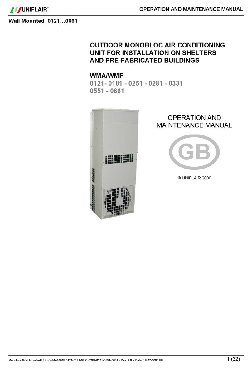
Uniflair Amico User manual

VERSION: 1.2
DATE:OCTOBER2012
LANGUAGE: ENGLISH
AMICO
Installation Manual
AMICO

2
VERSION: 1.2 DATE: OCTOBER 2012
UNIFLAIRSPA POLICYISONE OF CONTINUOUSTECHNOLGICALINNOVATIONANDTHECOMPANY
THEREFORERESERVESTHERIGHTTOAMENDANYDATAHEREINWITHOUTPRIORNOTICE.
GB

3
Contents
GENERALINSTRUCTIONS 4
Informationcontainedinthemanual 4
Symbols 4
Storage 4
Storageafteruse 4
Disposal 4
Disposalof the machine 4
SAFETY 6
GeneralInstructions 6
Warningforliftingandtransportation 6
Warningsforinstallation 6
Intendeduse 6
Warningsforuse 6
Safetyduringmaintenancework 6
INTRODUCTION 7
Presentation of the system 7
DIRECTEXPANSIONUNIT–AIRCOOLED 10
Technical characteristics 10
DIRECTEXPANSIONUNIT-WATERCOOLED 10
Technical characteristics 10
DIRECTEXPANSIONUNIT–AIRCOOLED 11
Technical characteristics 11
DIRECTEXPANSIONUNIT-WATERCOOLED 11
Technical characteristics 11
Operatingdescription 12
Nameanddescription of the principle components 13
Checksto be made on delivery 16
Unloadingtheunit 16
Characteristicsof the installation area 16
Positioning of the unit 16
Openingandremovalofthefrontpanel 17
Electrical connections 18
Internalprotectionpanels 18
Connectiontothe drains 19
Refrigerantconnectionsonair cooled units 20
Type of oil recommended with COPELAND compressors
22
ypeofoilrecommendedwithDANFOSS-MANEUROP
compressors 22
Connectionforwatercooledunits 22
MANUALSTARTUPAND SHUTDOWNOFTHE UNIT 23
SETTINGANDADJUSTMENT 24
Selecting the power supply of the fans 24
Settingtheregulation and safety devices 27
Settingthepressostatic valve (optional on chilledwater
cooledmodelsonly) 27
Setting the air flow sensor 27
Setting the dirty filter sensors 27
MAINTANENCE 28
Three-monthlychecks 28
Controllisemestrali 28
Six-monthly checks 28
Annual checks 28
Checksto be performedevery sixty months 28
Cleaningandrepalcingthefilters 28
Troubleshooting 29
CHILLEDWATERUNIT– CENTRIFUGALFANS 33
Technical characteristics 33
UNITA’ADACQUAREFRIGERATA-VENTILATORI
RADIALICONTECNOLOGIAE.C. 34
Technical characteristics 34
Operatingdescription 35
Nameanddescription of the principle components 36
Checksto be made on delivery 38
Unloadingtheunit 38
Characteristicsof the installation area 38
Positioning of the unit 38
Internalprotectionpanels 40
Electrical connections 40
Connectiontothewater drain 41
Hydraulicconnections 42
Filling the hydraulic circuit 42
Filling the primary circuit 42
Filling the hydraulic circuits of the conditioners 42
MANUALSTARTUPANDSHUTDOWN OFTHEUNIT 43
SETTINGANDADJUSTMENT 43
Selecting the power supply of the fans 43
Settingtheregulation and safety devices 46
Setting the air flow sensor 47
Setting the dirty filter sensors 47
MAINTENANCE 47
Three-monthlychecks 47
Six-monthly checks 47
Annual checks 47
Cleaningandrepalcingthefilters 48
Servomotorandchilled watervalve 48
Servomotorandhotwatervalve 48
Troubleshooting 49
ACCESSORIES 51
Humidifier 51
Operating principle 52
Feed water 52
Connections 52
Maintenance 53
Electric heaters 54
Temperatureandhumiditysensor 55
Connectiontofresh air intake 56
Maintenance 56
Dischargetemperaturethresholdsensor(onlyon
CHILLEDWATER models) 57

4
GENERAL INSTRUCTIONS
Information contained in the manual
Thepresentmanualdescribes theAmicoconditioningunits.
It supplies general information and safety instructions, unit
transportation and installation information, as well as
necessary information about how to use the units.
It is an integral part of the air conditioning unit.
Thedescriptionsandillustrationsinthismanualareunbinding;
"Uniflair S.p.A." reserves the right to make any alterations it
seesfitinordertoimprovetheproductwithouthavingtoupdate
this document.
The illustrations and images in this manual are examples
only and may differ from practical situations.
Symbols
Thefollowinggraphicandlinguistic symbols have beenused
in this manual:
WARNING! This message may appear before
certain procedures. Failure to observe this
message may cause damage to equipment.
WARNING! This message may appear before
certain procedures. Failure to observe this
message may cause injury to the operators and
damage the equipment.
Storage
The following conditions must be respected should the air
conditionerrequirestoringforagiven period of time:
The packing must be kept intact.
Theplaceofstoragemustbedry(<85%R.H.)andprotected
againstthesun(temperature<50°C).
Storage after use
Theairconditionermustbepackagedwhenstored for a long
time.
Disposal
The air conditioner is mainly made of recyclable materials
which should be separated from the rest of the unit before it
is disposed. When disposing of the gas and oil inside the
refrigerating circuit, consult a specialist company.
Disposal of the machine
Thefollowinginstructionsdealwith the disposal ofUNIFLAIR
machines. The procedures described below are guidelines
only, provided to make the machine disassembling easier.
Thepurposeoftheseoperationsistoachievehomogeneous
materialquantities for disposal or recycling.
Theseinstructionsarefollowed by alistofthepossibletypical
CER2002codes to allow an easier disposalof the machine
parts. WARNING! Observe the safety precautions at
work wearing the suitable individual protection
devices (IPD) and using the appropriate
equipments.
WARNING! Maintenance and service operations
(disassembling included) must be performed by
qualified and expert personnel, aware of the
essential precautions.
PRELIMINARY OPERATIONS
Power supply and data processing system:
• Turnthemachine off andunplugitfromthe powersupply
and from the communication system.
WARNING! The circuits can be pressurised; any
maintenance and service operation must only
be carried out by expert and qualified personnel,
aware of the essential safety precautions.
WARNING! The machine can contain hot water:
adopt all of the essential safety cautions.
Hydraulic circuit:
• Drain the hydraulic circuit and disconnect the hydraulic
line.
Refrigerating circuit:
• Purge the refrigeration system with suitable recovery
equipmentstoavoidgasleakagein the environment.
DISASSEMBLING THE MACHINE
Thefollowingparagraphsdescribethemainmacrocomponents
to facilitate the disassembling, disposal and recycling of
materialswithappropriatefeatures.
To disassemble the machine properly, follow the guidelines
providedbelow.
• ELECTRICALPANEL
Removetheelectricalpanelanddisposeitspartsfollowing
theproceduresprovidedbytherelevant standards. The
models equipped with a "clock board" in the electrical
panel have a service battery which must be disposed
separately.
-Materials:electronicparts,electricalcables,metal and
plastic supports, batteries.
• COVERPANELS
Remove the metal cover and protection panels of the
machine.
Thepanelscan be made of polypairedmaterials,that is
insulatingmaterial together withmetal. In thiscase, se-
paratethedifferentelements.
- Materials: galvanized sheet, aluminium, soundproof
panels:expandedpolyurethane,thermoinsulatingpanels:
mineralwool.

5
• AIRFILTERS
Removetheairfilters.
- Materials: metallic net, synthetic fibre.
• FINNEDCOIL
Removethefinnedcoils from the machine.
- Materials: copper, aluminium, steel.
• HUMIDIFIER
Ifa humidifier is installed, removeit.
-Materials:polypropylene, iron materials.
• ELECTRO-MECHANICALPARTS
Find and remove valves, electro-mechanical and
electronic parts (three-way valves, sensors, etc.) from
themachine.
• RESISTANCES
Removethe resistances if theyare installed.
-Materials:aluminium,inseparablecopper+magnesium
oxide.
• PIPES AND PARTS OF THE REFRIGERATING
CIRCUIT
Find the connection pipes installed in the machine and
separatethem from the other elements.
Pipescanbe caulked: in this case,beforerecovery,se-
paratethe insulating material fromthe metal pipe.
Even the elements of the refrigerating circuit are
consideredaspipes: joints or valves.
- Materials: copper, brass, cast iron, steel and plastic.
• PUMP
Removethepumpfromthemachine.
-Materials: pump.
• CONDENSER
Removethecondenser, if installed.
The condenser contains the elements of a machine,
equippedwithasmallelectricalpanel,fansandathermal
exchange battery, usually characterized by aluminium
structureandfeetmade of varnished steel.
- Materials: electrical elements, aluminium, steel
(varnished).
• BRAZEDPLATEEXCHANGER
Ifinstalled,removethebrazedplateexchanger.
- Materials: INOX AISI braze welding, with an alloy
containingalargeamountofsilver.
• FANS
Remove the fans. Disassemble the metal frame and
proceed with the recycling of the metal alloy.
-Materials: electro-mechanical elements, ironwrecks.
WARNING! The fans of some machine models
are integral part of the carrying structure.
Removing the fans can compromise the stability
of the frame. We recommend to pay attention
during disassembling operations.
• COMPRESSORSANDLIQUIDSEPARATORS
WARNING! Pay attention to oil contained in the
compressors. Avoid any loss of oil during
operations. If possible, dispose of oil and
compressors separately.
Finallyremovetheliquidseparatorsandthecompressors
fromthemachine base.
-Materials: liquid separators and compressors
• METALBASE
Proceed with the recycling of the metal base.
-Materials:galvanisedsheet.
WARNING! Waste deriving from machine
disassembly must be disposed of and classified
according to CER codes only consulting
authorised and specialist companies.
The following chart contains a partial list of the typical CER
codes applied to waste deriving from disassembling, so it
must be considered just as an indication.
STNEMELE SEDOC2002REC
selbaclacirtcelE114071
slairetamcitsalP911061
stroppuslateM711061
teehsdesinavlaG704071
muinimulA2
04071
tencillateM504071
erbifcitehtnyS302051
reppoC104071
ssarB104071
noritsaC504071
leetS704071
saggnitaregirfeR10
6041
yrettaB406061
lacinahcem-ortcele,spmuP srosserpmoc,stnemele 409071

6
SAFETY
General Instructions
WARNING! Removal of, or tampering with,
safety devices is a violation of EUROPEAN
SAFETYSTANDARDS.
WARNING! During installation authorised
personnel must wear individual safety devices.
UniflairS.p.Awillonlyconsideritselfresponsibleforthesafety,
reliabilityandperformance of the machine if:
• repair work has only been carried out by authorised
personnel;
• theelectricinstallationconforms to the standardscurrently
inforce;
• the devices are used in conformity with the relative
instructions.
Carefullyreadthis instructionmanualbeforecarryingoutany
kind of use or maintenance work on units.
Installation, maintenance and use must be carried out
respecting all of the work safety standards.
Theoperatorresponsible for the above mentionedservices
mustbesuitablyspecialisedandpossessexpertknowledge
ofthedevices.
UniflairS.p.Arefusesallresponsibilityfordamagetopeople
orobjects due to theinobservance of the safety standards.
Warning for lifting and transportation
Liftingandtransportation of the units mustbecarried out by
specialisedpersonnelasdescribedintherelativeparagraphs.
The load must always be solidly anchored to the bearing
elementoftheliftingequipmentandmeansoftransport.No-
onemustremain nearthesuspendedload, norintheworking
areaofthe crane, forklift truck or anyotherlifting equipment
ormeansof transport. Adopt all ofthecautions provided by
therelevantsafetystandards,inordertopreventanypossible
damageto people or objects.
Warnings for installation
Any type of work on the electrical installation must only be
carried out by specialised technicians who are experts in
this field.
Specialised technical personnel must use appropriate
equipmentwhencheckingthegroundingofdevices.
Installation may only take place in locations where there is
NO public access.
Intended use
Amicoairconditioningunitshavebeendesignedandproduced
to carry out air conditioning, within the limits and methods
described in the present manual. The air conditioners must
beusedexclusivelyininternal environments.
No modifications may be made to the units or their parts
without explicit written consent from Uniflair S.p.A.
Warnings for use
Only use the machinery for the purpose for which it was
designedandmanufactured.
Environmental limits for use
The environmental conditions for the use of Amico air
conditionersarefallwithinthefollowingvalues:
•Tmin=18°C •Tmax=30°C
•%rHmin=30% • %rHmax=70%
Safety during maintenance work
Allrepairworkmustbecarriedoutbyprofessionallyqualified
personnelauthorisedbyUniflair S.p.A.
Unplug the machine form the power supply before starting
anymaintenancework.
Whiledrawing up this manual, wehave considered all of the
operationswhicharepartofnormal maintenance operations.
N.B.Donot carry out any work whichhasnot been specified
in this manual.

7
AIR FLOW
IntheAMICOconditioners,theair can flow upwards or downwards(UPFLOW/ DOWNFLOW)
DOWNFLOW
Downflowunits(withdownwardsairdischarge)handlelarge
volumes of air which are distributed uniformly into the
environmentbymeansofavoidunder a raised access floor.
The air is sucked in through the upper section or the front
sectionoftheunitdirectlyfromthe environment, or through a
sectionofconduitconnectedtothe false ceiling ortoducting.
INTRODUCTION
Presentation of the system
TheAMICOprecision air conditioningunitsaredesignedfor civil use andforallenvironmentscharacterized by thepresence
ofequipmentwithahightechnological content: telephone and internetexchanges,dataprocessingcentres,meteorological
rooms,laboratoriesandclimate controlled warehouses.
TheAmico series consists of 2 types of conditioners:
• Direct expansion units
• Chilled water units
UPFLOW
TheUpflowairconditioningunits(withupwardsdischargeof
thetreatedair)aredesignedfordistributionof the air directly
into the environment with or without a discharge plenum or
through a system of ducting or by means of a false ceiling.
Thesuctionoftheairis normally from the front side of the air
conditioner,however,versionsarealsoavailablewithrecovery
oftheairfrom the rear of the airconditionerorfrom the base
support of the unit.

8
s
Identifyingprefix of the Amicofamily
Airdischarge
U=Upflow(upwardsdischarge)
D=Downflow(downwards discharge)
Operatingtypology
C = Chilled water units
A=Air cooled direct expansion units
W = Water cooled direct expansion units
Fantypology
V = Radial Electronically Commutated fans
C=Centrifugalfans
MODELS
The code which distinguishes the models is composed of 4 characters:
IDENTIFICATONPLATE
Theairconditioner can be identified bytheplate which is placed inthe electrical panel of the machine.The model and any
eventualaccessories which are installed areindicated by an "X"in the corresponding box
Theplatecarriesthe following data:
•Modeland series number of themachine.
•Type of power supply.
•Power absorbed by the unit and the single components.
•Currentabsorbed by the unitand the single components.
•Theset points of the coolingcircuitpressostatic valve and safetyvalve.
•Typeofrefrigerant.
•Loadingorpre-loadingof each cooling circuit.
Indicativecoolingcapacity
Numberofcooling circuits
Powersupplyvoltage
A = 400 V / 3Ph (+N) / 50 Hz
B = 230 V / 1 Ph / 50 Hz
FAC-SIMILE

9
SYMBOLSAPPLIEDTOTHEMACHINES
LOBMYSGNINAEM
egatlovhgiH
segdeprahS
strapgnivoM
SYMBOLSAPPLIED TO THE PACKAGES
LOBMYSGNINAEM
erachtiweldnah:ELIGARF
yrdaniderotsebtsumtinudegakcapeht:SNOITIDNOCPMADNIEROTSTONOD ecalp
ti
nudegakcapehtfoytivargfoertnecehtswohs:YTIVARGFOERTNEC
secruostaehmorfyawaderotsebtsumtinueht:TAEHMORF
YAWAPEEK
tinudegakcapehtfonoitisoptcerrocehtsetacidni:PUEDISSIHT
ehtnihtiwecalpaniderotsebtsumtinudegak
capeht:STIMILERUTAREPMET stimilerutarepmetdetacidni
skoohgnisustinudegakcapehttfiltonod:SKOOHESUTONOD
de
kcatsebtontsumstinudegakcapeht:KCATSTONOD

10
DIRECT EXPANSION UNIT – AIR COOLED
CENTRIFUGAL FANS
Technical characteristics
1) Unit in complete version (includingpackaging)
2) Nominal airflow–Maximumfanpowersupply
4) Minimum air flow only allowed forunitwithout electrical resistances
DIRECT EXPANSION UNIT - WATER COOLED
CENTRIFUGAL FANS
Technical characteristics
1) Unit in complete version (includingpackaging)
2) Nominal airflow–Maximumfanpowersupply
3) Data refer to Tb.s.=24°C - R.H.=50% TIN MIX=30°C TOUT MIX=35°C
4) Minimumair flow only allowed forunit without electrical resistances
SDAC/SUAC
Model 0151B 0151A 0251B 0251A 0331A 0351A 0501A 0601A
Height mm 1740 1740 1740 1740 1740 1740 1740 1740
Width mm 550 550 550 550 850 850 1200 1200
Depth mm 450 450 450 450 450 450 450 450
Weight
1
kg
140 140 140 140 180 180 220 220
Number of refrigerant circuits - 1 1 1 1 1 1 1 1
Number of compressors - 1 -SCROLL 1 -SCROLL 1 -SCROLL 1 -SCROLL 1 -SCROLL 1 -SCROLL 1 -SCROLL 1 -SCROLL
Refrigerant - R410A R410A R410A R410A R410A R410A R410A
R410A
Air flow m
3
/h
1626 1626 1731 1731 2977 3301 4482 4482
E.S.P Maximum
2
Pa
116 116 78 78 132 78 20 20
Minimum air flow
4
m
3
/h
1040 1040 1040 1040 1950 1950 3020 3020
Power supply voltage V/ph/Hz 230/1N/50 400/3N/50 230/1N/50 400/3N/50 400/3N/50 400/3N/50 400/3N/50 400/3N/50
SDWC/SUWC
Model
0151B 0151A 0251B 0251A 0331A 0351A 0501A 0601A
Height mm 1740 1740 1740 1740 1740 1740 1740 1740
Width mm 550 550 550 550 850 850 1200 1200
Depth mm 450 450 450 450 450 450 450 450
Weight
1
kg
145 145 145 145 185 185 230 230
Number of refrigerant circuits - 1 1 1 1 1 1 1 1
Number of compressors - 1 -SCROLL 1 -SCROLL 1 -SCROLL 1 -SCROLL 1 -SCROLL 1 -SCROLL 1 -SCROLL 1 -SCROLL
Refrigerant - R410A R410A R410A R410A R410A R410A R410A
R410A
Air flow m
3
/h
1626 1626 1731 1731 2977 3301 4482 4482
E.S.P Maximum
2
Pa
116 116 78 78 132 78 20 20
Nominal water flow
3
l/h
1355 1350 1740 1705 2152 2746 3586 3912
Minimum air flow
4
m
3
/h
1040 1040 1040 1040 1950 1950 3020 3020
Power supply voltage V/ph/Hz 230/1N/50 400/3N/50 230/1N/50 400/3N/50 400/3N/50 400/3N/50 400/3N/50 400/3N/50

11
DIRECT EXPANSION UNIT – AIR COOLED
RADIAL FANS WITH E.C. TECHNOLOGY
Technical characteristics
1) Unit in complete version (including packaging)
2) Nominalairflow–Maximum fan power supply
4)Unitwithout electrical heaters
DIRECT EXPANSION UNIT - WATER COOLED
RADIAL FANS WITH E.C. TECHNOLOGY
Technical characteristics
1) Unit in complete version (includingpackaging)
2) Nominal airflow–Maximumfanpowersupply
3) Data refer to Tb.s.=24°C - R.H.=50% TIN MIX=30°C TOUT MIX=35°C
4) Minimumair flow only allowed forunit without electrical resistances
SDWV/SUWV
Model
0151B 0151A 0251B 0251A 0331A 0351A 0501A 0601A
Height mm 1740 1740 1740 1740 1740 1740 1740 1740
Width mm 550 550 550 550 850 850 1200 1200
Depth mm 450 450 450 450 450 450 450 450
Weight
1
kg 132 132 132 132 185 185 260
Number of refrigerant circuits - 1 1 1 1 1 1 1 1
Number of compressors - 1 -SCROLL 1 -SCROLL 1 -SCROLL 1 -SCROLL 1 -SCROLL 1 -SCROLL 1 -SCROLL 1 -SCROLL
Refrigerant - R410A R410A R410A R410A R410A R410A R410A
R410A
Air flow m
3
/h
1644 1644 1722 1722 3204 3439 4499 5202
E.S.P Maximum
2
Pa
193 193 155 155 178 123 153 40
Nominal water flow
3
1357 1354 1739 1704 2183 2764 3590 4015
Minimum air flow
4
m
3
/h
1040 1040 1040 1040 1950 1950 3020 3020
Power supply voltage V/ph/Hz 230/1N/50 400/3N/50 230/1N/50 400/3N/50 400/3N/50 400/3N/50 400/3N/50 400/3N/50
SDAV/SUAV
Model
0151B 0151A 0251B 0251A 0331A 0351A 0501A 0601A
Height mm 1740 1740 1740 1740 1740 1740 1740 1740
Width mm 550 550 550 550 850 850 1200 1200
Depth mm 450 450 450 450 450 450 450 450
Weight
1
kg 132 132 132 132 185 185 260
Number of refrigerant circuits - 1 1 1 1 1 1 1 1
Number of compressors - 1 -SCROLL 1 -SCROLL 1 -SCROLL 1 -SCROLL 1 -SCROLL 1 -SCROLL 1 -SCROLL 1 -SCROLL
Refrigerant type - R410A R410A R410A R410A R410A R410A R410A
R410A
Nominal air flow m
3
/h
1644 1644 1722 1722 3204 3439 4499 5202
Max. E.S.P
2
Pa
193 193 155 155 178 123 153 40
Minimum air flow
4
m
3
/h
1040 1040 1040 1040 1950 1950 3020 3020
Power supply voltage V/ph/Hz 230/1N/50 400/3N/50 230/1N/50 400/3N/50 400/3N/50 400/3N/50 400/3N/50 400/3N/50

12
AIR COOLED DIRECT EXPANSION UNITS (DXA)
The air cooled DX units extract heat from the room and transfer it to
theoutsideusing air cooled refrigerantheatexchangers (condensers).
Theroomunitandexternalcondenserformanautonomoussealedcircuit
onceinstalled.TheUNIFLAIRremote condensersusedwithAMICOunits
includeaprecise electronic system to regulatethe fan speed to ensure
trouble-freeoperationthroughouttheyearundera widerangeofexternal
airtemperatures. Special attention has beenpaidtotheacoustic design
ofthecondenserstominimisenoiselevels. Awiderangeofcombinations
isavailableto meet different site requirements.
WATER COOLED DIRECT EXPANSION UNITS (DXW)
In the DX water cooled units, the heat extracted from the room is
transferredto water via a stainlesssteel brazed plate exchanger within
the unit.
The cooling water may be fed from the mains supply or a well (open
circuit), or recycled in a closed loop cooled by external coolers.
Inthe latter case, an anti-freezemixture of water andethyleneglycol is
normallyused.
The water cooled units have the advantage that the refrigerant circuits
arechargedandsealedinthefactory.Thismakesinstallationextremely
simple,eliminatingtheneed for any site-installed refrigerant pipework.
Operating description

13
Name and description of the principle components
G12
A
D
F1
A Userterminal
B Electricalpaneldoor
C Coverpanel
D Electricalpanel
E Air Filter
F Fans
G Coolingcircuit
H Brazed plate heat
exchanger(presentinchilled
watermodels)
H
U
C
Model SDA*/SDW* Model SUA*/SUW*
A
B
C
F
G
E
F

14
Description of the components
A- User terminal
Allowsthe unit to be turned on or off and the configuration
andvisualization of the condition ofthemachine.
• A1 LCDDisplay
•A2 ALARM key:visualization and reset of alarms;when
the alarm is activated, it flashes red
•A3 PRG key: access to the configuration menu
•A4 ESC key : exit from the screens
•A5 UP key : scroll through the menu
•A6 ENTER key : confirm
•A7 DOWN key: scroll through the menu
A2
A4
A5
A6
A7
A1
B - Electrical panel door
Allows access to the electrical panel of the machine.
D5
D1
D2
D3
D6
D
7A
I
D?
D
7B
D
7C
D
7D
C-Coverpanel
Allow access to the internal components of the machine.
D - Electrical panel
• D1 Magnetothermic
- auxiliary
- heater(optional)
- humidifier(optional)
- fans
- compressors
• D2 Interfaceboard
• D3 Dirtyfilter sensor
• D4 Airflowsensor
• D5 Main switch
• D6 Terminalboard
•D7AInput/outputelectrical supply cables
•D7BInput/outputelectrical auxiliary cables
•D7CInput/output condensing unit supply(optional)-Only
on units with air cooling
•D7DEntrance/exit signalcables(RS485 and/or LAN)
• D8 Phasesequencerelay
E
E -Air Filter
Filtertheairreleased into the environment
F - Fans
F1Fanspeedregulator
A3
F1
FD8
E
D
D5

15
HH1
G - Cooling circuit
• G1 Compressor
• G2 Highpressureswitch
• G3 SchraderValve
• G4 Lowpressuretransducer
• G5 Shut-offvalve
• G6 Circuit Exit
• G7 Circuitentrance
• G8 Liquidreceiver
• G9 Dehydration filter
• G10 Flow sight glass
• G11 Electronicthermostaticvalve
• G12 Evaporating coil
H - Brazed plate heat exchanger (present on water cooled
units)
• H1 Input/output hydraulic circuit
I-Room temperature and humidity sensor
I
G12
G2
GG3
G11
G10
G1
G9
G8
HH1
G4

16
Checks to be made on delivery
WARNING! Dispose of the packaging in
appropriate collection points.
TheAmico unit comes packaged in a wooden case or fixed
onapallet and wrapped in transparentfilm.
Checkthat the delivery is completeand inform the carrierof
anydamagetotheunitwhichmay be attributed too careless
orinappropriatetransportation.
Lifting and moving the unit must be carried out by a
mechanical lifter, supplied with a sling made up of textile
belts,which,fixedunderthe machine, limits excessivestress
ontheupper edges.
Thefollowingmust be contained within thepackaging:
• TheAmicounit;
• AmicoUse and Installation Manual;
• Amico unit electrical diagrams;
• Amico unit cooling circuit diagrams;
• Amico unit installation diagrams;
• List of spare parts;
• CE declaration with a list of the European standards to
whichthe machine must conform;
• guaranteeconditions
Unloading the unit
Tounloadtheunitfromthepallet,carryoutthefollowingpro-
cedure:
• movethepallet as near aspossibleto where the unit isto
beinstalled;
• not tilt or turn the unit upsidedown;use a ramp to avoid
anydamageto the unit during unloading;
• remove the blocking screws which fix the unit to the
pallet;
• carefully push the unit along the ramp until it reaches
thefloor.
Characteristics of the installation area
WARNING! The unit must be installed internally
and protected from adverse conditions.
Theunitispredisposedforinstallationonraisedaccessflooring
using mounting frames or appropriate floor stands supplied
onrequestfromUniflair. However, the upflow units(upwards
air flow) with air intake through the rear or front can also be
installedon floors whichare not raised.
Theareaofinstallationmusthavethefollowingcharacteristics:
• to facilitate maintenance, leave a clearance (distance
D)ofat least 700mm free infront of the unit. Checkthat
theairintake and dischargeconnectionsarenotblocked
in any way, not even partially;
• ahorizontalandevenfloor;
• the electrical energy distribution system has been
produced in respect of CEI standards, suitable for the
characteristics of the unit;
• a cold water distribution implant (if a humidifier is to be
installed);
• implant for connection to the condensing unit;
• externalair outlet (if a freshair intake is to beinstalled);
• ifortherefrigeratinggasdrainseeparagraph"Connection
to gas drain";
• condensing drain circuit and/or humidifier.
WARNING! The preparation of the installation
area must be carried out as indicated in the
installation drawing attached to the machine
documentation.
Positioning of the unit
WARNING! If the surface where the unit is placed
is not even and horizontal, there is a risk of an
overflow from the condensation tray. A
maximumheight difference of 5mm between the
ends of the unit is allowed.
Installation on raised access flooring
Installation on raised access flooring occurs by means of a
mounting frame. The frame enables the installation of the
unitbeforethe raised floor is installed, increasedabsorption
ofnoiseandvibrationsandthefacilitationofconnectingipes
andcables.
The upflow models (upwards air flow) with rear or frontal air
intake may be installed without using the mounting frame.

17
Installation of the mounting frame
To install the unit on raised flooring using the mounting fra-
me,carryout the following procedures:
• a flexible seal at least 5 mm thick should be fitted
betweentheraisedfloorpanelsandthe mounting frame
which should also be isolated from the metallic floor
structure;
• position the unit of the mounting frame and fix it using
the M8 screw inserts found on the base of the unit.
Installation on flooring which is not raised
Installationon flooring which isnot raised can occurwithout
using bases, but only on upflow models
(upwardsairflow) with rearorfrontalairintake. Installation on
this type of floor does not require any additional operation
besidesthat of normal positioning.
Installation of the floor stand
To install the unit on the floor stand, carry out the following
procedures:
• position the unit on the floor stand;
• fixthe unit tothe floor standusing the M8screw inserts
found on the base of the unit.
Opening and removal of the front panel
Toopenandremovethefront panelproceedasfollows:
• rotatetheclosingblocks, as indicated by the arrows,by
onequarterof a turn;
• firmlygrip the panel;
• lift and tilt away from the unit until complete extraction.
SU**
SD**
Base of unit
Floorstand

18
Electrical connections
WARNING! Electrical connection of the machine
to the power supply must ONLY be carried out
by a qualified electrician.
WARNING! Electrical lines must be established
in full respect of CEI standards.
WARNING! Before establishing the electrical
connection, make sure that the power supply is
off. Also ensure that it is not possible to
reconnect the power during the operation.
WARNING! The power supply voltage must be ±
10%
To carryout the electrical connectionsof the machine tothe
powersupply, carryoutthefollowing procedures:
• use suitable equipment to check the efficiency of the
groundingsystem;
• checkthatthevoltageandnetworkfrequencycorrespond
to those of the machine (see identification label);
• to access the electricalpanel it is necessary toremove
thefront panel of the unitbyrotating the closing blocks,
indicated by the arrows, by one quarter of a turn (in the
SU**modelstheelectricalpanelissituatedinthe upper
part of the unit);
• pass the cables inside using the power supply cable inlet
D7A;
Internal protection panels
Thefancompartmentandelectricalheatersare protected by
a sheet metal covering for safety reasons and to allow the
opening of the external panels without interfering with the
safety devices on the unit.
SU**
SU
SD
D7A/C
D7B/DD7A/CD7B/D
• referto the wiring diagramandconnect the cable tothe
main switch D5.
G12
D
D7B/D
D5
E
D
D5
SD**

19
SD./SU.A-W (C-V)
0151B - 0251B
SD./SU.A-W (C-V)
0151A - 0251A - 0331A - 0351A - 0501A - 0601A
SD./SU.C (C-V)
0200A - 0250A - 0300A - 0400A - 0600A
Oncetheconnections have been made, pourwater into the
condensate drain until the siphon inside the unit is full.
The external drainage tube must be siphoned to avoid
unpleasantodoursandanoverflowof the water from thetray
ofthehumidifier. Maintainaminimumslopeof1%downstream
ofthe siphon.
Once the connections have been made, pour water into the
condensate collection tray of theAmico unit and in the con-
densate collection tray of the humidifier until both siphons
arefull.
U7
U4
Connectiontothehumidifier(optional)and to the drains
of the building
WARNING! The water discharged from the
humidifier is at a very high temperature. The
drainage tube has to withstand high
temperatures (at least 100°C) and must be kept
away from electrical cables.
Connect the drainage tube of the unit to the collection tray
(U4)ofthehumidifier.
Connectthedrainagetube ofthehumidifier(U7)tothe drains
ofthebuildingusingarubberorplastictube,whichisresistant
to high temperatures (minimum 100 °C) with an internal
diameterof 22 mm.
To connect the auxiliary connections to the terminal board,
carryoutthefollowingprocedures:
• pass the cables through the power supply cable inlet
D7B;
• refertothewiring diagram and carry out the connection
tothe terminal board.
DIGITALCONFIGURABLE INPUTS
Terminal board 51-20
-User
- ON - OFF Remote
-Flooding sensor (SAS)
-Tools (ATA-BTA-AUA-BUA)
Terminal board 52-20
-User
-ON-OFFRemote
-Fire-smoke(SFF)
Remote signalling
Terminal board 980 - 990
- Signalling of the state of the unit (CV)
G12
D
D7B/D
D5
*P2:REMOVE WHEN “SAS” IS INSTALLED
*P3:REMOVEWHEN“ATA-BTA-AUA-BUA”AREINSTALLED
Connection to the drains
Thecondensedwaterdrainsfromthe traythroughasiphoned
flexible tube fitted in the unit.
If the conditioner is fitted with a humidifier, the condensate
drain tray and the humidifier drain connection must be
connected to the drains of the building.
Direct connection to the drains of the building
Connect the drainage tube of the unit to the drains of the
buildingusingarubberorplastictubewithaninternaldiameter
of 25 mm.
Theexternaldrainagetubemustbesiphonedinordertoavoid
unpleasant odours. Maintain a minimum slope of 1%
downstreamofthesiphon.
POWERSUPPLYCABLE
(at customers at care)
POWERSUPPLYCABLE
(at customers at care)
Drain
%
Siphon
Minimum slope
Drain
%
Siphon
Minimum slope

20
Refrigerant connections on air cooled units
Installation guide
WARNING! The pipes must always be protected from the sun.
A:Discharge line
B: Liquid line
C:Thermalinsulation
Recommended connections
SUA*0151
SDA*0151
SUA*0251
SDA*0251
SUA*0331
SDA*0331
SUA*0351
SDA*0351
SUA*0501
SDA*0501
SUA*0601
SDA*0601
De De De De De De
A 12mm 12mm 14mm 16mm 18mm 18mm
B 12mm 12mm 12mm 14mm 14mm 16mm
Table of contents
Other Uniflair Air Conditioner manuals
Popular Air Conditioner manuals by other brands

Rohnson
Rohnson R-892 user manual

Carrier
Carrier 51 Series operating instructions

Mitsubishi Electric
Mitsubishi Electric MSY-GJ10VA operating instructions

Mitsubishi Electric
Mitsubishi Electric Mr. SLIM PU-1.6VLJA Technical & service manual

Morgan
Morgan MAC-COOL1B user manual

Hatari
Hatari AC Turbo1 user manual

Samsung
Samsung AM CXV Series installation manual

Bryant
Bryant EVOLUTION 16 186B Product data

Trane
Trane 4TTL6018A1000A Installation and operation manual

Kooltronic
Kooltronic Trimline NP47 Series Operator's manual

Pentair
Pentair McLean Thermal T Series instruction manual

Toshiba
Toshiba RAV-SM567CTP-E installation manual