Uniflair LEONARDO EVOLUTION TDAR 511A User manual

LEONARDO EVOLUTION
INSTALLATION MANUAL
LEONARDO EVOLUTION
VERSION:1.7
DATE: FEBRUARY2010
LANGUAGE: ENGLISH

2
VERSION: 1.7 DATE: FEBRUARY 2010
UNIFLAIRSPA POLICYISONE OF CONTINUOUSTECHNOLGICALINNOVATIONANDTHE COMPANY
THEREFORERESERVESTHERIGHTTOAMENDANYDATAHEREINWITHOUTPRIORNOTICE.
GB

3
GENERALINSTRUCTIONS 4
Informationcontainedinthemanual 4
Symbols 4
Storage 4
Storageafteruse 4
Disposal 4
Disposalof the machine 4
SAFETY 6
GeneralInstructions 6
Warningforliftingandtransportation 6
Warningsforinstallation 6
Intendeduse 6
Warningsforuse 6
Safetyduringmaintenancework 6
INTRODUCTION 7
Presentation of the system 7
LEONARDOEVOLUTION-DIRECTEXPANSION 10
Technical characteristics 10
Operatingdescription 13
Nameanddescription of the principle components 14
Checksto be made on delivery 17
Unloadingtheunit 17
Characteristicsof the installation area 17
Positioning of the unit 17
Dooropeningandremovalofthepanels 18
Dooropening 18
Internalprotectionpanels 19
Electrical connections 20
Connectiontothe drains 21
Connectionto the gas drain 21
Refrigerantconnectionsonair cooled units 22
Choosingthediameter of the discharge tube 22
R407C 23
R410A 24
BACKFLOWLINEDIMENSIONING(LIQUID) 27
Typeofoilrecommended with COPELAND
compressors 29
Type of oil recommended with MANEUROP
compressors 29
Type of oil recommended with SANYOcompressors 29
Type of oil recommended with Scrolltech HCJ 072-HLJ
083compressors 29
Connectionforwatercooledunits 30
MANUALSTARTUPANDSHUTDOWN OFTHEUNIT 31
SETTINGANDADJUSTMENT 32
Selecting the power supply of the fans 32
Settingtheregulation and safety devices 35
Settingthepressostatic valve (optional on chilledwater
cooledmodelsonly) 35
Setting the air flow sensor 35
Setting the dirty filter sensors 35
MAINTANENCE 36
Three-monthlychecks 36
Six-monthly checks 36
Annual checks 36
Checksto be performedevery sixty months 36
Cleaningandrepalcingthefilters 36
Troubleshooting 38
LEONARDOEVOLUTION- CHILLED WATER 42
Technicalcharacteristics 42
Operatingdescription 43
Nameanddescription of the principle components 44
Checksto be made on delivery 46
Unloadingtheunit 46
Characteristicsof the installation area 46
Positioning of the unit 46
Openingofthedoorandremovalofthepanels 47
Internalprotectionpanels 48
Electrical connections 49
Connectiontothewater drain 50
Hydraulicconnections 51
Filling the hydraulic circuit 51
Filling the primary circuit 51
Filling the hydraulic circuits of the conditioners 51
MANUALSTARTUPANDSHUTDOWN OFTHEUNIT 52
SETTINGANDADJUSTMENT 53
Selecting the power supply of the fans 53
Settingtheregulation and safety devices 57
Setting the air flow sensor 58
Setting the dirty filter sensors 58
MAINTENANCE 58
Three-monthlychecks 58
Six-monthly checks 58
Annual checks 58
Cleaningandreplacingthefilters 59
Servomotorandchilled watervalve 60
Servomotorandhotwatervalve 60
Troubleshooting 61
LEONARDOEVOLUTIONENERGYSAVING 63
Technicalcharacteristics 63
Operatingdescription 64
Nameand description of the principleparts 65
LEONARDOEVOLUTIONTWIN-COOL 69
Technicalcharacteristics 69
Operatingdescription 71
Nameanddescription of the principle components 72
ACCESSORIES 77
Humidifier 77
Operating principle 78
Feed water 78
Connections 78
Maintenance 79
Electric heaters 80
Temperatureandhumiditysensor 81
Connectiontofresh air intake 82
Maintenance 83
Dischargetemperaturethresholdsensor(onlyon
CHILLEDWATER models) 83
Contents

4
GENERAL INSTRUCTIONS
Information contained in the manual
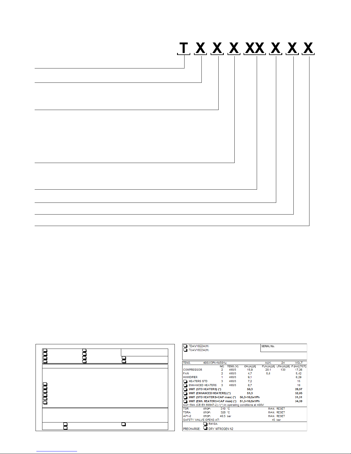
The present manual describes the Leonardo Evolution
conditioningunits.Itsuppliesgeneralinformationandsafety
instructions,unit transportation and installation information,
aswellasnecessaryinformationabouthow to use the units.
It is an integral part of the product.
Thedescriptionsandillustrationsinthismanualareunbinding;
"Uniflair S.p.A." reserves the right to make any alterations it
seesfitinordertoimprovetheproductwithouthavingtoupdate
this document.
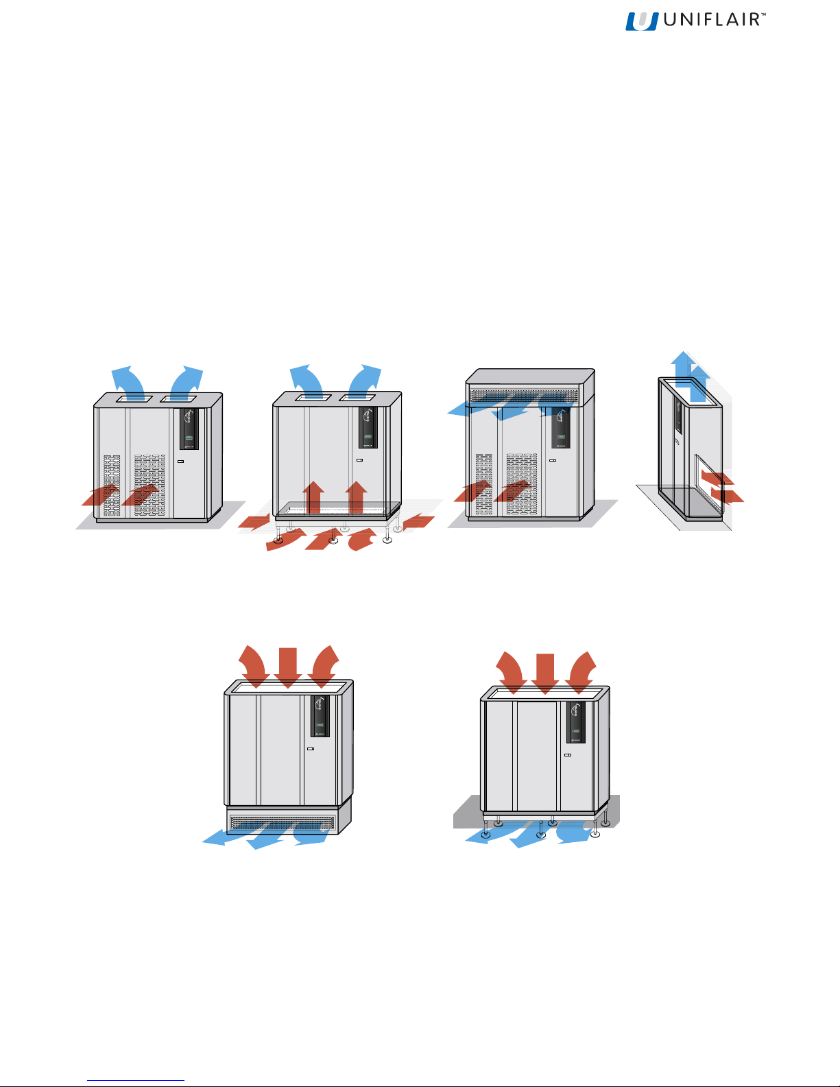
The illustrations and images in this manual are examples
only and may differ from practical situations.
Symbols
Thefollowinggraphicandlinguistic symbols have been used
in this manual:
WARNING! This message may appear before
certain procedures. Failure to observe this
message may cause damage to equipment.
WARNING! This message may appear before
certain procedures. Failure to observe this
message may cause injury to the operators and
damage the equipment.
Storage
The following conditions must be respected should the unit
requirestoringforagivenperiod of time:
The packing must be kept intact.
Theplaceofstoragemustbedry(<85%R.H.)andprotected
againstthesun(temperature<50°C).
Storage after use
The unit must be packaged when stored for a long time.
Disposal
Theunitismainlymadeofrecyclablematerials which should
be separated from the rest of the unit before it is disposed.
When disposing of the gas and oil inside the refrigerating
circuit, consult a specialist company.
Disposal of the machine
Thefollowinginstructionsdeal withthedisposalofUNIFLAIR
machines.
Theproceduresdescribedbelowareguidelinesonly,provided
to make the machine disassembling easier. The purpose of
these operations is to achieve homogeneous material
quantities for disposal or recycling.
Theseinstructionsare followedbyalistofthe possibletypical
CER2002codes toallowan easier disposal of the machine
parts. WARNING! Observe the safety precautions at
work wearing the suitable individual protection
devices (IPD) and using the appropriate
equipments.
WARNING! Maintenance and service operations
(disassembling included) must be performed by
qualified and expert personnel, aware of the
essential precautions.
PRELIMINARY OPERATIONS
Power supply and data processing system:
• Turnthemachine offandunplugit fromthepowersupply
and from the communication system.
WARNING! The circuits can be pressurised; any
maintenance and service operation must only
be carried out by expert and qualified personnel,
aware of the essential safety precautions.
WARNING! The machine can contain hot water:
adopt all of the essential safety cautions.
Hydraulic circuit:
• Drainthe hydraulic circuit anddisconnectthe hydraulic
line.
Refrigerating circuit:
• Purge the refrigeration system with suitable recovery
equipmentstoavoidgasleakagein the environment.
DISASSEMBLING THE MACHINE
Thefollowingparagraphsdescribethemainmacrocomponents
to facilitate the disassembling, disposal and recycling of
materialswithappropriatefeatures.
To disassemble the machine properly, follow the guidelines
providedbelow.
• ELECTRICALPANEL
Remove the electrical panel and dispose its parts
following the procedures provided by the relevant
standards.Themodelsequippedwitha"clockboard"in
the electrical panel have a service battery which must
bedisposedseparately.
-Materials:electronicparts,electricalcables,metaland
plastic supports, batteries.
• COVERPANELS
Remove the metal cover and protection panels of the
machine.
Thepanelscanbemadeof polypaired materials, that is
insulating material together with metal. In this case,
separatethedifferentelements.
- Materials: galvanized sheet, aluminium, soundproof
panels: expanded polyurethane, thermoinsulating
panels:mineralwool.

5
• AIRFILTERS
Removetheairfilters.
- Materials: metallic net, synthetic fibre.
• FINNEDCOIL
Removethefinnedcoils from the machine.
- Materials: copper, aluminium, steel.
• HUMIDIFIER
Ifa humidifier is installed, removeit.
-Materials:polypropylene, iron materials.
• ELECTRO-MECHANICALPARTS
Find and remove valves, electro-mechanical and
electronic parts (three-way valves, sensors, etc.) from
themachine.
• RESISTANCES
Removethe resistances if theyare installed.
-Materials:aluminium,inseparablecopper+magnesium
oxide.
• PIPES AND PARTS OF THE REFRIGERATING
CIRCUIT
Find the connection pipes installed in the machine and
separatethem from the other elements.
Pipescanbe caulked: in this case,beforerecovery,se-
paratethe insulating material fromthe metal pipe.
Even the elements of the refrigerating circuit are
consideredaspipes: joints or valves.
- Materials: copper, brass, cast iron, steel and plastic.
• PUMP
Removethepumpfromthemachine.
-Materials: pump.
• CONDENSER
Removethecondenser, if installed.
The condenser contains the elements of a machine,
equippedwithasmallelectricalpanel,fansandathermal
exchange battery, usually characterized by aluminium
structureandfeetmade of varnished steel.
- Materials: electrical elements, aluminium, steel
(varnished).
• BRAZEDPLATEEXCHANGER
Ifinstalled,removethebrazedplateexchanger.
- Materials: INOX AISI braze welding, with an alloy
containingalargeamountofsilver.
• FANS
Remove the fans. Disassemble the metal frame and
proceed with the recycling of the metal alloy.
-Materials: electro-mechanical elements, ironwrecks.
WARNING! The fans of some machine models
are integral part of the carrying structure.
Removing the fans can compromise the stability
of the frame. We recommend to pay attention
during disassembling operations.
• COMPRESSORSANDLIQUIDSEPARATORS
WARNING! Pay attention to oil contained in the
compressors. Avoid any loss of oil during
operations. If possible, dispose of oil and
compressors separately.
Finallyremovetheliquidseparatorsandthecompressors
fromthemachine base.
-Materials: liquid separators and compressors
• METALBASE
Proceed with the recycling of the metal base.
-Materials:galvanisedsheet.
WARNING! Waste deriving from machine
disassembly must be disposed of and classified
according to CER codes only consulting
authorised and specialist companies.
The following chart contains a partial list of the typical CER
codes applied to waste deriving from disassembling, so it
must be considered just as an indication.
STNEMELE SEDOC2002REC
selbaclacirtcelE114071
slairetamcitsalP911061
stroppuslateM711061
teehsdesinavlaG704071
muinimulA2
04071
tencillateM504071
erbifcitehtnyS302051
reppoC104071
ssarB104071
noritsaC504071
leetS704071
saggnitaregirfeR10
6041
yrettaB406061
lacinahcem-ortcele,spmuP srosserpmoc,stnemele 409071

6
SAFETY
General Instructions
WARNING! Removal of, or tampering with,
safety devices is a violation of EUROPEAN
SAFETYSTANDARDS.
WARNING! During installation authorised
personnel must wear individual safety devices.
UniflairS.p.Awillonlyconsideritselfresponsibleforthesafety,
reliabilityandperformance of the machine if:
• repair work has only been carried out by authorised
personnel;
• theelectricinstallationconforms to thestandardscurrently
inforce;
• the devices are used in conformity with the relative
instructions.
Carefullyreadthis instruction manualbeforecarryingoutany
kind of use or maintenance work on the units.
Installation, maintenance and use must be carried out
respecting all of the work safety standards.
Theoperatorresponsible for the above mentionedservices
mustbesuitablyspecialisedandpossessexpertknowledge
ofthedevices.
UniflairS.p.Arefusesallresponsibilityfordamagetopeople
orobjects due to theinobservance of the safety standards.
Warning for lifting and transportation
Liftingandtransportation of the units mustbecarried out by
specialisedpersonnelasdescribedintherelativeparagraphs.
The load must always be solidly anchored to the bearing
elementoftheliftingequipmentandmeansoftransport.No-
onemustremain nearthesuspendedload, norintheworking
areaofthe crane, forklift truck or anyotherlifting equipment
ormeansof transport. Adopt all ofthecautions provided by
therelevantsafetystandards,inordertopreventanypossible
damageto people or objects.
Warnings for installation
Any type of work on the electrical installation must only be
carried out by specialised technicians who are experts in
this field.
Specialised technical personnel must use appropriate
equipmentwhencheckingthegroundingofdevices.
Installation may only take place in locations where there is
NO public access.
Intended use
LeonardoEvolutionairconditioningunitshavebeendesigned
and produced to carry out air conditioning, within the limits
and methods described in the present manual. The air
conditioners must be used exclusively in internal
environments.
No modifications may be made to the units or their parts
without explicit written consent from Uniflair S.p.A.
Warnings for use
Only use the machinery for the purpose for which it was
designedandmanufactured.
Environmental limits for use
The environmental conditions for the use of Leonardo air
conditionersarefallwithinthefollowingvalues:
•Tmin=18°C •Tmax=30°C
• %rHmin=30% • %rHmax=70%
Safety during maintenance work
Allrepairworkmustbecarriedoutbyprofessionallyqualified
personnelauthorisedbyUniflair S.p.A.
Unplug the machine form the power supply before starting
anymaintenancework.
Whiledrawing up this manual, wehave considered all of the
operationswhicharepartofnormal maintenance operations.
N.B.Donot carry out any work whichhasnot been specified
in this manual.

7
AIR FLOW
IntheLEONARDO EVOLUTION conditioners, the air can flow upwardsordownwards(UPFLOW/ DOWNFLOW).
UPFLOW
Upflowunits(withupwardsairdischarge)aredesignedtodistributetheairthroughasystemofductsorbymeansofafalse
ceiling.Air intake is usually through the front of the unit, but versions are also available with air intakethroughtherearor the
base of the unit.
INTRODUCTION
Presentation of the system
TheLeonardoEvolution™ precisionairconditionersaredesignedfor environmentswhicharecharacterisedby thepresence
of highly technologically advanced equipment: telecomms and internet centres, data processing rooms and any type of
environmentwhichischaracterized by high concentrations of power.
The Leonardo Evolution series consistsof 4 types of conditioners:
• Direct expansion
• Chilled water
• EnergySaving
• Twin-Cool
DOWNFLOW
Downflowunits(withdownwardsairdischarge)handlelargevolumesofairwhicharedistributeduniformlyintotheenvironment
bymeansofavoid under a raisedaccessfloor.Theairenterstheunit directly from theenvironment,orthroughaventilated
orfalse ceiling.

8
IdentifyingprefixoftheLeonardofamily
Airdischarge
U=Upflow(upwardsdischarge)
D=Downflow(downwards discharge)
Operatingtypology
C = Chilled water units
A=Air cooled direct expansion units
W = Water cooled direct expansion units
T =Air cooled twin cool units
D = Water cooled twin cool units
E = Energy saving units
Fantypology
V = Radial Electronically Commutated fans
R = Radial fans
MODELS
The code which distinguishes the models is composed of 4 characters:
IDENTIFICATONPLATE
Theunits can be identified bythe identification plate whichisplaced in the electricalpanelof the machine. Themodel and
anyeventual accessories which areinstalled are indicated by an "X" inthe corresponding box
Theplatecarriesthe following data:
•Modeland series number of themachine.
•Type of power supply.
•Power absorbed by the unit and the single components.
•Currentabsorbed by the unitand the single components.
•Theset points of the coolingcircuitpressostatic valve and safetyvalve.
•Typeofrefrigerant.
•Loadingorpre-loadingof each cooling circuit.
Indicativecoolingcapacity
Numberofcompressorsinstalled
Numberofcooling circuits
Powersupplyvoltage
A = 400 V / 3Ph (+N) / 50 Hz
B = 230 V / 1 Ph / 50 Hz
TDAV1422A(H) TDEV1422A(H)
SERIAL No.
TUAV1422A(H) TUEV1422A(H)
TDWV1422A(H) TDDV1422A(H) TDTV1422A(H)
TUWV1422A(H) TUDV1422A(H) TUTV1422A(H)
TENS. 400V/3Ph+N/50Hz AUX. 24 VOLT
NO. TENS. (V) OA (A) [/1] FLA (A) [/1] LRA (A) [/1] P (kW ) [TOT]
COMPRESSOR 2 400/3 10,7 14,0 98 11,2
FAN 2 400/3 4,7 5,6 05,42
HUMIDIFIER 1 400/3 9,1 0,0 0 6,29
HEATERS STD 3 400/3 7,2 0,0 0 15
ENHANCED HEATERS 3 400/3 8,7 0,0 0 18
UNIT (STD HEATERS) (*) 41,7 26,02
UNIT (ENHANCED HEATERS) (*) 46,0 29,02
UNIT (STD HEATERS+CAL max) (*) 41,7+10,5x1Ph 28,36
UNIT (ENH HEATERS+CAL max) (
*
)
46+10 5x1Ph
31 36
UNIT
(ENH
.
HEATERS+CAL
max
)
(*)
46+10
,
5
x
1Ph
31
,
36
Icu=15kA (CEI EN 60947-2) / (*) in operating conditions at 400V
TSR
STOP:
310 °C MAN. RESET
TSRA
STOP:
328 °C MAN. RESET
AP1-2
STOP:
26,5 bar MAN. RESET
SAFETY VALVE OPENS AT: 30 bar
CHARGE: R407C kg/circ. R22 kg/circ.
PRECHARGE: DRY NITROGEN N2
FAC-SIMILE
FAC-SIMILE

9
SYMBOLSAPPLIEDTOTHEMACHINES
LOBMYSGNINAEM
egatlovhgiH
segdeprahS
strapgnivoM
LOBMYSGNINAEM
erachtiweldnah:ELIGARF
yrdaniderotsebtsumtinudegakcapeht:SNOITIDNOCPMADNIEROTSTONOD ecalp
ti
nudegakcapehtfoytivargfoertnecehtswohs:YTIVARGFOERTNEC
secruostaehmorfyawaderotsebtsumtinueht:TAEHMORF
YAWAPEEK
tinudegakcapehtfonoitisoptcerrocehtsetacidni:PUEDISSIHT
ehtnihtiwecalpaniderotsebtsumtinudegak
capeht:STIMILERUTAREPMET stimilerutarepmetdetacidni
skoohgnisustinudegakcapehttfiltonod:SKOOHESUTONOD
de
kcatsebtontsumstinudegakcapeht:KCATSTONOD
SYMBOLSAPPLIED TO THE PACKAGES

10
LEONARDO EVOLUTION - DIRECT EXPANSION
Technical characteristics
AIRCOOLEDDIRECTEXPANSION UNITS WITH BACKWARD CURVEDBLADEFANS
RAUT-RADTledoM A115 A116 A127 A227 A129 A229 A1201 A2201
thgieHmm06910691069106910691069106910691
htdiWmm01010101013101310131013101310131
htpeDmm057057568568568568568568
thgieWgk0820130347
44034744034744
stiucrictnaregirferforebmuN11121212
srosserpmocforebmuN 11222222
egatlovylppusrewoPV zH05/N+hp3/V004
RAUT-RADTledoM A1211 A2211 A1231 A2231 A2241 A2261 A2281
thgieHmm0691069106910691069106910691
htdiWmm1271127112711271271227122712
htpeDmm568568568568568568568
thgieWgk845955575585896417417
stiucrictnaregirferforebmuN1212222
srosserpmocforebmuN 2222 2 2 2
egatlovylppusrewoPVzH05/N+hp3/V004
RADTledoM 2222 2422 2252 2452 2482 2433
thgieHmm571257125712571257125712
htdiWmm085208520852085208520852
htpeDmm568568568568568568
thgieWgk01901981903904018901
stiucrict
naregirferforebmuN 2222 2 2
srosserpmocforebmuN242444
egatlovylppusrewoPVzH05/N+hp3/V004
RAUTledoM 2222 2422 2252 2452 2482 2433
thgieHmm069106910691069106910691
htdiWmm085208520852085208520852
htpeDmm568568568568568568
thgieWgk01901981903904018901
stiucrict
naregirferforebmuN 2222 2 2
srosserpmocforebmuN242444
egatlovylppusrewoPVzH05/N+hp3/V004

11
VAUT-VADTledoM 115 116 127 227 129 229 1201 2201
thgieHmm06910691069106910691069106910691
htdiWmm01010101013101310131013101310131
htpeDmm057057568568568568568568
thgieWgk08208203474
4034744034744
stiucrictnaregirferforebmuN 111212 1 2
srosserpmocforebmuN 112222 2 2
egatlovylppusrewoPVzH05/N+hp3/V004
AIRCOOLEDDIRECTEXPANSION UNITS WITH ECBACKWARD CURVEDBLADE FANS
VAUT-VADTledoM 1211 2211 1231 2231 2241 2261 2281
thgieHmm0691069106910691069106910691
htdiWmm0271027102710271171217121712
htpeDmm568568568568568568568
thgieWgk845955575585896417417
s
tiucrictnaregirferforebmuN1212222
srosserpmocforebmuN 22222 2 2
egatlovylppusrewoPVzH05/N+hp3/V004
VADTledoM 2222 2422 2252 2452 2482 2433
thgieHmm571257125712571257125712
htdiWmm085208520852085208520852
htpeDmm568568568568568568
thgieWgk01901981903904018901
stiucrict
naregirferforebmuN 2222 2 2
srosserpmocforebmuN242444
egatlovylppusrewoPVzH05/N+hp3/V004
VAUTledoM 2222 2422 2252 2452 2482 2433
thgieHmm069106910691069106910691
htdiWmm085208520852085208520852
htpeDmm568568568568568568
thgieWgk01901981903904018901
stiucrict
naregirferforebmuN 2222 2 2
srosserpmocforebmuN242444
egatlovylppusrewoPVzH05/N+hp3/V004

12
CHILLEDWATER DIRECTEXPANSIONUNITS WITH BACKWARD CURVEDBLADE FANS
RWUT-RWDTledoM 116 129 1231 2261 2281
thgieHmm06910691069106910691
htdiWmm01010131027117121712
htpeDmm057568568568568
thgieWgk013034575417417
stiucrictnaregirferforebmuN 1112 2
srosserpmocforebmuN12222
egatlovylppusrewoPVzH05/N+hp3/V004
RWDTledoM 2422 2452 2482 2433
thgieHmm5712571257125712
htdiWmm0852085208520852
htpeDmm568568568568
thgieWgk699020102110411
stiucrictnaregirferforebmuN2222
s
rosserpmocforebmuN4444
egtalovylppusrewoPVzH05/N+hp3/V004
RWUTledoM 2422 2452 2482 2433
thgieHmm0691069106910691
htdiWmm0852085208520852
htpeDmm568568568568
thgieWgk699020102110411
stiucrictnaregirferforebmuN2222
s
rosserpmocforebmuN4444
egtalovylppusrewoPVzH05/N+hp3/V004

13
AIR COOLED DIRECT EXPANSION UNITS (DXA)
The air cooled DX units extract heat from the room and transfer it to
theoutsideusing air cooled refrigerantheatexchangers (condensers).
Theroomunitandexternalcondenserformanautonomoussealedcircuit
onceinstalled.TheUNIFLAIRremotecondensersusedwithLEONARDO
units include a precise electronic system to regulate the fan speed to
ensuretrouble-freeoperationthroughouttheyear under a wide rangeof
externalairtemperatures. Specialattention hasbeenpaidtotheacoustic
design of the condensers to minimise noise levels. A wide range of
combinationsisavailable to meet different site requirements.
WATER COOLED DIRECT EXPANSION UNITS (DXW)
In the DX water cooled units, the heat extracted from the room is
transferredto water via a stainlesssteel brazed plate exchanger within
the unit.
Thecoolingwatermay be fed from the mainssupply,acooling tower or
a well (open circuit), or recycled in a closed loop cooled by external
coolers.
Inthe latter case, an anti-freezemixture of water andethyleneglycol is
normallyused.
The water cooled units have the advantage that the refrigerant circuits
arechargedandsealedinthefactory.Thismakesinstallationextremely
simple,eliminatingtheneed for any site-installed refrigerant pipework.
CHILLEDWATERDIRECTEXPANSION UNITS WITH ECBACKWARDCURVEDBLADE FANS
VWUT-VWDTledoM 116 129 1231 2261 2281
thgieHmm06910691069106910691
htdiWmm01010131027117121712
htpeDmm057568568568568
thgieWgk082034575417417
stiucrictnaregirferfo
rebmuN11122
srosserpmocforebmuN 12222
egatlovylppusrewoPVzH05/N+hp3/V004
Operating description
VWDTledoM 2422 2452 2482 2433
thgieHmm5712571257125712
htdiWmm0852085208520852
htpeDmm568568568568
thgieWgk699020102110411
stiucrictnaregirferforebmuN2222
s
rosserpmocforebmuN4444
egtalovylppusrewoPVzH05/N+hp3/V004
VWUTledoM 2422 2452 2482 2433
thgieHmm0691069106910691
htdiWmm0852085208520852
htpeDmm568568568568
thgieWgk699020102110411
stiucrictnaregirferforebmuN2222
s
rosserpmocforebmuN4444
egtalovylppusrewoPVzH05/N+hp3/V004

14
Name and description of the principle components
A
B
C
A User terminal
B Electrical panel door
C Coverpanels
D Electrical panel
E Filters
F Fans
G Cooling circuit
H Brazedplateheatexchanger
(present in chilled water
models)
H
E
D
F
G
D
E
F
G
MODELS TD./ TU. 511 ÷ 1822
MODELS TD./ TU. 2222 ÷ 3342

15
Description of the components
A- User terminal
Allowsthe unit to be turned on or offand the configuration
andvisualization of the condition ofthemachine.
• A1 LCDDisplay
•A2 ALARM key: visualization andresetof alarms;
when the alarm is activated, it flashes red.
•A3 PRG key: access to the configuration menu
•A4 ESC key : exit from the screens
•A5 UP key : scroll through the menu
•A6 ENTER key : confirm
•A7 DOWN key: scroll through the menu
A2
A3
A4
A5
A6
A7
A1
B - Electrical panel door
Allows access to the electrical panel of the machine.
C-Coverpanels
Allow access to the internal components of the machine.
D - Electrical panel
•D1 Magnetothermic
-auxiliary
-heater(optional)
-humidifier(optional)
-fans
-compressors
• D2 Interfaceboard
• D3 Dirtyfiltersensor
• D4 Airflowsensor
• D5 Main switch
• D6 Terminalboard
• D7A Input/output electrical supply cables
• D7B Input/output electrical auxiliarycables
• D7C Input/output condensing unit supply
• (optional) - Only on units with air cooling
• D7D Entrance/exitsignalcables (RS485 and/or LAN)
• D8 Phasesequencerelay
• D9 Maximum pressure manostat (only for mod. TD.
2222÷3342)
D5
D1
D2
D3
D6
D
7A
D4
D8
D
7B
D
7C
D
7D
MODELS TD./ TU. 511 ÷ 1822
MODELS TD./ TU. 2222 ÷ 3342
F
E
F1
E - Filters
Filtertheairreleased into the environment
F - Fans
Allowthe diffusion ofair into the room
• F1ATRTransformer: allowsthesettingofthefanrotation
speed
D2 D1
D
7A
D
7C
D
7B
D
7D
D3D4 D9
D5 D6D8

16
HH1
G1
G2
G3
G4 G5
G6 G7G8
G10
G11
G9
G - Cooling circuit
• G1 Compressor
• G2 Highpressureswitch
• G3 SchraderValve
• G4 SafetyValve
• G5 Shut-offvalve
• G6 Circuit Exit
• G7 Circuitentrance
• G8 Liquidreceiver
• G9 Dehydrationfilter
• G10 Flow sight glass
• G11 Electronicthermostaticvalve
G12
• G12 Evaporatingcoil
H - Brazed plate heat exchanger (present on water cooled
units)
•H1 Input/outputhydrauliccircuit
II-Room temperature and humidity sensor

17
Checks to be made on delivery
WARNING! Dispose of the packaging in
appropriate collection points.
TheLeonardoEvolutionunitsarepackagedin woodencrates
oranchoredtoapallet and covered in cardboard.
Checkthat the delivery is completeand inform the carrierof
anydamagetotheunitwhichmay be attributed too careless
or inappropriate transportation. In particular, check any
eventual damage to the panel in which the user terminal is
mounted.
Lifting and moving the unit must be carried out by a
mechanical lifter, supplied with a sling made up of textile
belts,which,fixedunderthe machine, limits excessivestress
ontheupper edges.
Thefollowingmust be contained within thepackaging:
• TheLeonardoEvolutionunit;
• LeonardoUseandInstallationManual;
• Leonardounitelectricaldiagrams;
• Leonardounitcooling circuit diagrams;
• Leonardounitinstallationdiagrams;
• List of spare parts;
• CE declaration with a list of the European standards to
whichthe machine must conform;
• guaranteeconditions
Unloading the unit
Tounloadtheunitfromthepallet,carryoutthefollowingpro-
cedure:
• move the pallet as near as possible to where the unit is
to be installed;
• not tilt or turn the unit upsidedown;
• use a ramp to avoid any damage to the unit during
unloading;
• remove the blocking screws which fix the unit to the
pallet;
• carefully push the unit along the ramp until it reaches
thefloor.
Characteristics of the installation area
WARNING! The unit must be installed internally
and protected from adverse conditions.
Theunitispredisposedforinstallationonraisedaccessflooring
using mounting frames or appropriate floor stands supplied
onrequestfromUniflair.However, the upflow units(upwards
air flow) with air intake through the rear or front can also be
installedon floors whichare not raised.
Theareaofinstallationmusthavethefollowingcharacteristics:
• to facilitate maintenance, leave a clearance (distance
D)ofat least 700mm free infront of the unit. Checkthat
theairintake and dischargeconnectionsarenotblocked
in any way, not even partially;
• ahorizontalandevenfloor;
• the electrical energy distribution system has been
produced in respect of CEI standards, suitable for the
characteristics of the unit;
• a cold water distribution implant (if a humidifier is to be
installed);
• implant for connection to the condensing unit;
• externalair outlet (if a freshair intake is to beinstalled);
• ifortherefrigeratinggasdrainseeparagraph"Connection
to gas drain";
• drainagesystem.
WARNING! The preparation of the installation
area must be carried out as indicated in the
installation drawing attached to the machine
documentation.
Positioning of the unit
WARNING! If the surface where the unit is placed
is not even and horizontal, there is a risk of an
overflow from the condensation tray. A
maximumheight difference of 5mm between the
ends of the unit is allowed.
Installation on raised access flooring
Installation on raised access flooring occurs by means of a
mounting frame. The frame enables the installation of the
unitbeforethe raised floor is installed, increasedabsorption
ofnoiseandvibrationsandthefacilitationofconnectingipes
andcables.
The upflow models (upwards air flow) with rear or frontal air
intake may be installed without using the mounting frame.
D

18
Installation of the mounting frame
To install the unit on raised flooring using the mounting fra-
me,carryout the following procedures:
• a flexible seal at least 5 mm thick should be fitted
betweentheraisedfloorpanelsandthe mounting frame
which should also be isolated from the metallic floor
structure;
• position the unit of the mounting frame and fix it using
the M8 screw inserts found on the base of the unit.
Installation on flooring which is not raised
Installationon flooring which isnot raised can occurwithout
using bases, but only on upflow models
(upwardsairflow) with rearorfrontalairintake. Installation on
this type of floor does not require any additional operation
besidesthat of normal positioning.
Installation of the floor stand
To install the unit on the floor stand, carry out the following
procedures:
• position the unit on the floor stand;
• fixthe unit tothe floor standusing the M8screw inserts
found on the base of the unit.
basamento
condizionatore
zoccolo
unità
Door opening and removal of the panels
Door opening
Toopenthe door of the unit, carry outthefollowingprocedu-
re:
• push the button and pull the handle lightly outwards;
• turnthehandle downwards until the door opens.
Removalofthefrontandsidepanels
To remove the front and side panels, carry out the following
procedure:
• firmlyhold the panel;
• lift and incline the panel outwards until it is completely
removed.
Q.E.
NOTE: After having removed the side panels, the non-
removableprotectivepanel,blocksaccessibilitytotheinside
ofthemachine.
Removal of the rear panels
Toremovethe rear panels,carryoutthe followingprocedure:
• unscrew, using a star screwdriver, the screws which fix
the panel at the top of the machine;
• firmlyhold the panel;
• lift and incline the panel outwards until it is completely
removed.
Fixing screws
Flexible seal Flexible seal
Mounting
frame
Raised
floor
Air conditioning unit
Base of unit
Floorstand

19
Internal protection panels
The technical compartment, the electric heaters and the
autotransformer fans are protected by internal protection
panels for safety reasons and to allow the opening of the
externalpanelswithouttriggeringtheunit's safety alarms. In
the figures below, the different types of internal protection
panelsareshown on various typesofmachines.
Beforeremovingtheinternalprotectionpanels,
disconnect the power supply by turning the main isolating
switch D5 to position "O", then wait until the fans stop and
the electrical heaters cool down.
MODELS TD. 511 ÷ 1822
MODELS TU. 511 ÷ 1822
MODELS TD. 2222 ÷ 3342
MODELS TU. 2222 ÷ 3342

20
Electrical connections
WARNING! Electrical connection of the machine
to the power supply must ONLY be carried out
by a qualified electrician.
WARNING! Electrical lines must be established
in full respect of CEI standards.
WARNING! Before establishing the electrical
connection, make sure that the power supply is
off. Also ensure that it is not possible to
reconnect the power during the operation.
WARNING! The power supply voltage must be ±
10%
To carry out theelectrical connections of themachine to the
powersupply,carryoutthefollowingprocedures:
• use suitable equipment to check the efficiency of the
groundingsystem;
• checkthatthevoltageandnetworkfrequencycorrespond
to those of the machine (see identification label);
• openthe door of theelectrical panel;
• removetheplasticscreenoftheelectricalpanelusing a
starscrewdriver;
D5
D
7A
D
7B
• pass the cables inside using the power supply cable inlet
D7A which connects to the main switch D5;
• refertothe wiring diagram andconnectthe cable to the
main switch D5.
2222 - 2242 - 2522 - 2542 - 2842 - 3342
POWERSUPPLYCABLE
(at customers at care)
POWERSUPPLYCABLE
(at customers at care)
This manual suits for next models
113
Table of contents
Other Uniflair Air Conditioner manuals
Popular Air Conditioner manuals by other brands

Matsui
Matsui MAT-9KACW manual

Ocean Breeze
Ocean Breeze OBZ-10ESN owner's manual

INVENTOR
INVENTOR V3MFI-24 user manual

Dettson
Dettson COND-UHD-09 Installation instructions and homeowner's manual

REMKO
REMKO SKT 521 Operating and installation instructions

Hitachi
Hitachi airHome 400 DJ Series Operation manual