9
REFRIGERANT CONNECTIONS
The condenser has male rotalock connections.
The condenser is factory charged with dry nitrogen to
prevent the ingress of humidity and the connections are
sealed with plugs.
BEFORE REMOVING THE PLUGS FROM THE
CONNECTIONS, DISCHARGE THE NITROGEN BY
MEANS OF THE NEEDLE VALVE ON THE INLET
MANIFOLD.
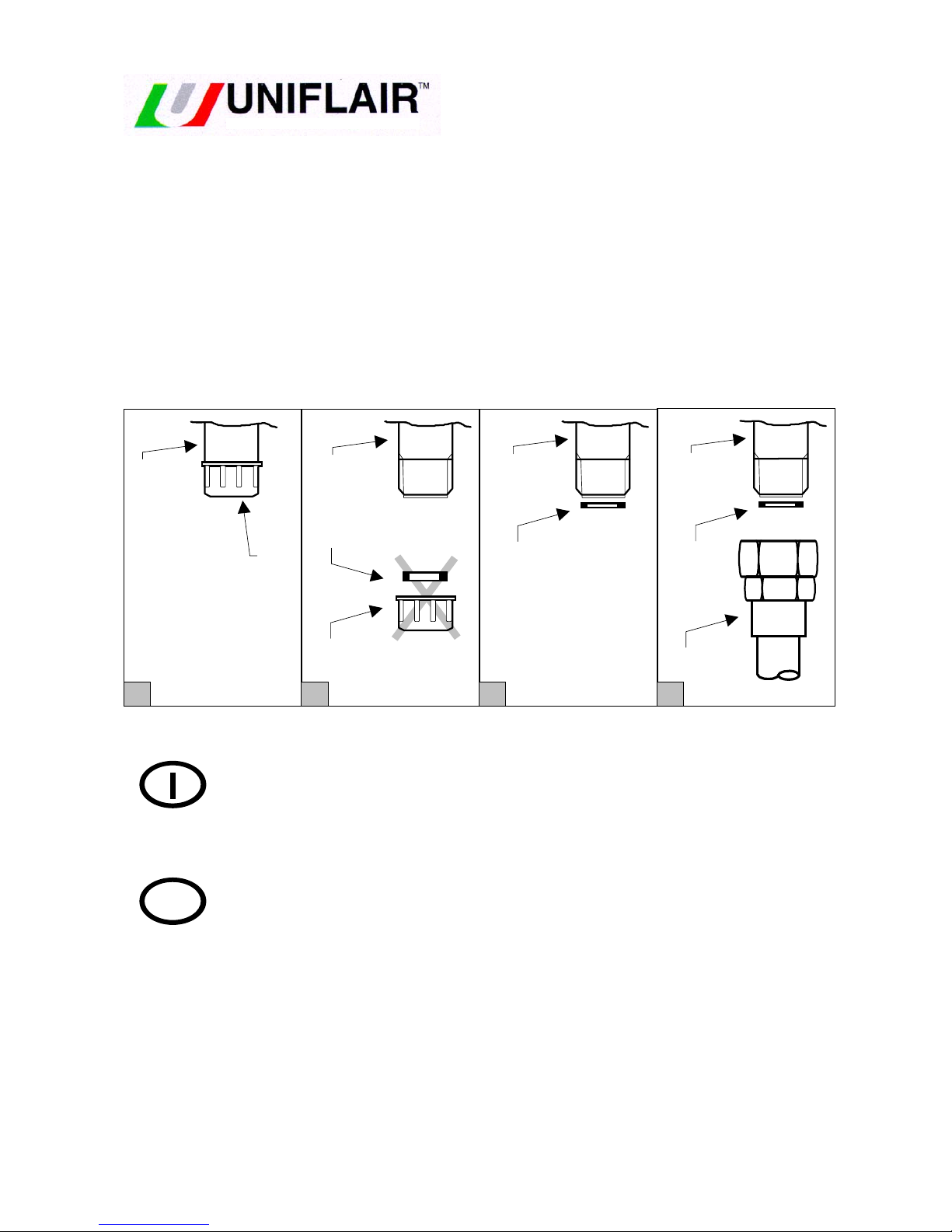
Connection to the condenser can be achieved with one of the
following rotalock connectors:
3a) straight connectors: see fig. 3a;
3b) right angle connectors (supplied on request): see fig 3b;
3c) service valves (supplied on request): see fig. 3c:
to which the interconnecting pipework is connected.
A: ROTALOCK
CONNECTIONS
B: SEAL
Fig. 3
Take care that the connections are correctly made and in
particular do not invert the inlet and outlet connections (see fig.
4)
Fig. 4
Run the refrigeration lines taking care to ensure the following
(see also fig. 5);
•use straight line routes wherever possible;
A: discharge line
B: liquid line
C: trap
Fig. 5
•incline the discharge line with a gradient of 1/100 in the
direction of flow to facilitate oil entrainment;
•make a ‘U’ trap in the discharge line at the bottom of any
vertical risers;
•thermally insulate the refrigerant liquid line wherever it may
be exposed to sun;
•avoid any contact between the discharge line and the liquid
line.
Carry out the evacuation and charging of the complete
refrigerant circuit.
ELECTRICAL CONNECTIONS
CABLE SIZES - PROTECTION
(see wiring diagram SECA ......... attached)
The condenser can be operated automatically and
autonomously (as a function of the refrigerant pressure ) and
therefore its power supply does not necessarily have to come
from the indoor unit to which it is connected. It can come from
the nearest convenient distribution board.
Check that the voltage and frequency of the power supply
correspond to the data shown on the nameplate of the
condenser.
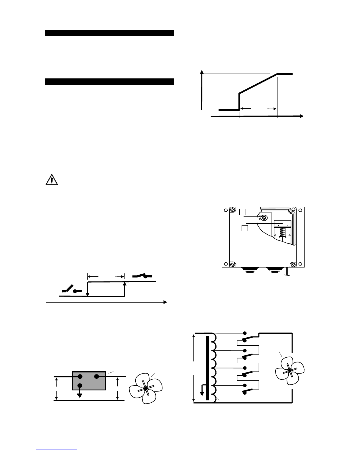
Connect the power supply cable to the isolator introducing the
cable into the switch box through an IP 55 rated cable gland
and screw the terminals down tightly.
The following table lists the principal electrical data needed for
the connection.
VOLTAGE No. kW FLA mm² FUS
CAL0231 230V/1ph/50 1 0,14 0,7 1,5 10 A
CAL0251 230V/1ph/50 1 0,14 0,7 1,5 10 A
CAL0331 230V/1ph/50 1 0,14 0,7 1,5 10 A
CAL0361 230V/1ph/50 2 0,28 1,4 1,5 10 A
CAL0511 230V/1ph/50 2 0,28 1,4 1,5 10 A
CAL0661 230V/1ph/50 2 0,28 1,4 1,5 10 A
CAL0801 230V/1ph/50 3 0,42 2,1 1,5 10 A
CAL1011 230V/1ph/50 3 0,42 2,1 1,5 10 A
CAL1301 230V/1ph/50 4 0,56 2,8 1,5 10 A
CAL1511 230V/1ph/50 5 0,70 3,5 1,5 10 A
CAL1801 230V/1ph/50 6 0,84 4,2 1,5 10 A
No. : Number of fans
kW kW : Nominal power
FLA A : Max. absorbed current
mm² mm² : Recommended cable size
FUS AT : Short circuit protection recommended
(for cable runs up to 30 m)
N.B. : The condenser is fitted with overload protection (bi-
metallic switch in each motor) but not against short circuit; so
feed the condenser via a suitable protection device (fuse or
circuit breaker of appropriate rating ).
OK
B
A
3a 3b
B
A
3c
B
A
B
1/100
A
max 5 m
max 30 m
1/100
A
Bmax 15 m
B
A
C
1/100