Uninet iColor LF700 User manual

iColor LF700

iColor LF700 Manual Version 3.6
Uninet
Copyright 2014 Page 2
I. Important Notice
For Users in Europe
This is a Class A product approved for industrial environments.
For Users in the United States
This equipment has been designed and tested to comply with the limits for a Class A digital device, pursuant
to Part 15 of the FCC Rules. These limits are designed to provide reasonable protection against harmful
interference when the equipment is operated in a commercial environment.
This equipment generates, uses, and can radiate radio frequency energy and, if not installed and used in
accordance with the instruction manual, may cause harmful interference to radio communications.
Operation of this equipment in a residential area is likely to cause harmful interference in which case the
user will be required to correct the interference at his own expense.
Trademarks Mentioned in this Manual
LF700, LF350, iColor, Summa, WinPlot and Rapid are registered trademarks or product names
of Uninet, RAPID LABEL SYSTEMS AND SUMMA.
• Windows XP, Windows Vista, Windows 7 and MS- DOS are registered trademarks or product names of
Microsoft Corporation.
• Intel and Pentium are trademarks or registered trademarks of Intel Corporation.
• Other company and product names may be registered trademarks or product names.
Changes or modifications not expressly approved by Uninet, which is responsible for FCC compliance,
could void the user’s authority to operate this equipment.
No part of this product or publication may be stored, reproduced, copied, or transmitted
in any form or by any means without the express permission of Uninet.
The product and the contents of this publication may be changed at any time without
prior notification.
Uninet has made the best efforts to keep this publication free from error, but if
you find any uncertainties or misprints, please call us or the dealer from where
you bought this equipment.
Uninet shall not be liable for any damages or losses resulting from the use or mis-use
of the equipment or this manual either directly
or indirectly.
!

iColor LF700 Manual Version 3.6
Uninet
Copyright 2014 Page 3
II. Waste Electrical & Electronic Equipment (WEEE) Directive
Directive 2002/96/EC of the European Parliament and of the Council.
The symbol (right) is shown on this product. It indicates that the product
should not be disposed of with regular household waste, but should be
disposed of separately.
Electrical and electronic equipment can contain materials that are hazardous to
the environment and human health and therefore should be disposed of at a
designated waste facility or returned to your retailer for the appropriate recycling
to take place.
If you wish to dispose of this product and the product still functions, please consider recycling / reusing it by
donating it to a charity shop, selling it or part-exchanging it with your retailer.
III. Warning symbols
Warning labels are attached to areas where care should be taken. Read and understand the positions and
contents thoroughly before operating the machine.
Make sure that all warning labels can be recognized. If text or illustrations cannot be seen clearly, clean or
replace the label. When cleaning warning labels, use a cloth with water or neutral detergent. Do not use any
solvent or gasoline products. If a warning label is damaged, lost, or cannot be recognized, replace the label.
IV. Warnings, Cautions and Notes
Safety terms in this manual and the contents of warning labels attached to the LF700 Cutter are
categorized into the following three types depending on the degree of risk (or the scale of accident).
Read the following explanations carefully, and follow the instructions in this manual.
Must be followed carefully to avoid death or serious bodily injury.
Must be observed to avoid slight or moderate bodily injury or damage to
whole or part of the product.
Contains important information and useful tips on the operation of the product.
!
WARNING
!

iColor LF700 Manual Version 3.6
Uninet
Copyright 2014 Page 4
V. Important Safety Instructions
1. General safety instructions that must be observed to use the equipment safely are explained below.
2.
Do not place the cutter in the following areas. Doing so may result in the LF700 cutter tipping or falling
over and causing serious injury:
• Unstable or loose surfaces
• Angled surfaces
• Areas subject to vibration by other equipment
3.
Do not stand on or place heavy objects on your LF700 cutter. Doing so may result in the cutter tipping or
falling over and causing injury.
4. Do not place the cutter in humid and dusty areas.
5.
Make sure to use the power cable packed with the LF700 you have purchased.
6. Do not use the power cable if it is damaged in any way. Doing so may result in electrical shock or fire.
7. Do not insert or drop metal or objects which are easily combustible through the openings such as the
ventilation hole of your cutter. Doing so may result in electrical shock or fire.
8. Do not operate the cutter if it has been contaminated by foreign substances or liquid spills as doing so may
result in electrical shock or fire. Immediately turn off the power switch, disconnect the power plug from the
electric socket, and contact your authorized dealer.
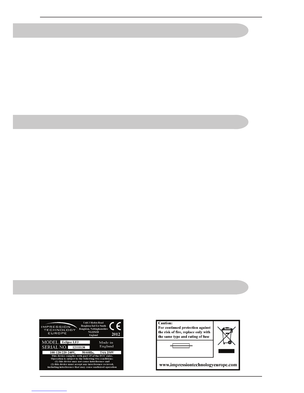
9. Make sure to use only the specified power supply (AC 100 V / 120 V - AC 220 V / 240 V). If the power
supply other than the specified voltage is used, it could cause an electric shock and fire.
10. Take power for the cutter directly from the power socket (AC 100 V / 120 V - AC 220 V / 240 V). Do
not use complex multiple plugs on the same socket. This could generate heat and might cause fire.
11. Make sure that the following is performed before parts replacement.
• Turn off the power to the printer.
• Remove the power cable from the power outlet. Not doing so may cause electric shock or damage
to the electric circuit.
• Unplug the cables connected to the printer. Failure to do so could result in damage to the printer.
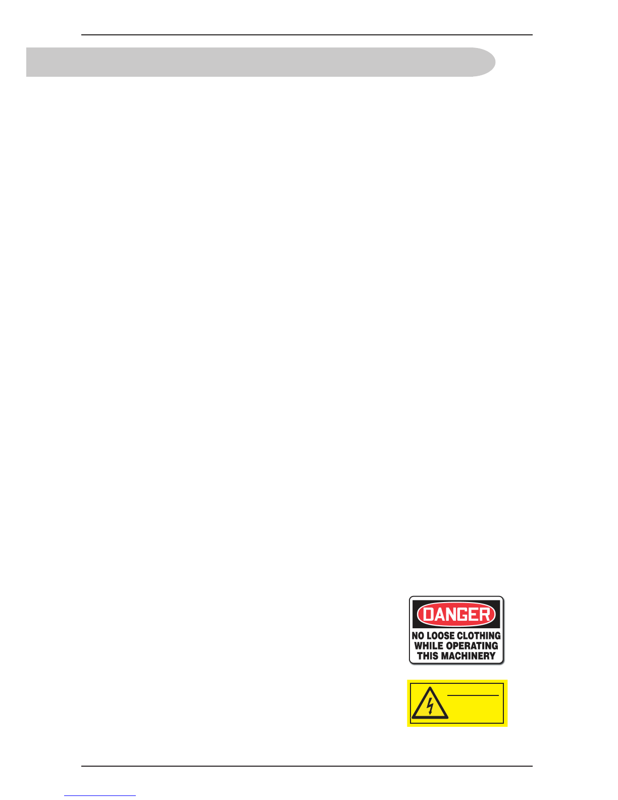
12. Do not wear any loose clothing and tie back any long hair
whilst operating this machine, failure to adhere to this warning
could result in serious injury.
13. Do not remove the rear cover with the power on, high voltage
power units are located behind the cover, only a trained LF350
Technician should remove the panel.

iColor LF700 Manual Version 3.6
Uninet
Copyright 2014 Page 5
VII. About this Manual
A. Purpose and Target Readers.
This manual explains the preparations and procedures for operating the iColor LF700.
This is a common User Guide for theiColor series of digital cutters. Unless specifically mentioned to
the contrary, the descriptions in this manual are common for all iColor series models.
This manual is designed to assist the end user in the use, maintenance and general troubleshooting of the
iColor series digital cutters. Before using the iColor series digital cutter you are required to read
and fully understand the contents and directions in this manual.
B. Manual Configuration.
1. Unpacking the machine.
2. Components & Product Overview.
Explains the features, part names, and functions of the digital cutter.
3. Initial Setup and Basic Operations.
Explains the procedures for the initial setup & basic operations of the digital cutter.
4. Cutting Labels.
Explains the procedures of preparation for cutting labels.
5. Maintenance
Explains daily and other periodical maintenance of the cutter.
6. Hints & Tips.
Explains troubles that may occur when using the cutter and how to solve them.

iColor LF700 Manual Version 3.6
Uninet
Copyright 2014 Page 6
VIII. Contents
Important Notice 2
Waste Electrical & Electronic Equipment Directive 3
Warning Symbols 3
Warning Cautions And Notes 3
Safety Instructions 4
About This Manual 5
Section 1: Preparation 8
9
10
10
10
11
Unpacking the LF700
Cutter Getting Started
LF700 Specifications
Serial and Fuse Plate
Machine Dimensions
Caution 12
Section 2: Getting To Know Your Machine 13
14-15
16
17
18
LF700
Components
Keypad
LCD Control Panel
LCD Screen
LF700 Cutting Head
19
Section 3: Computer Setup 20
21
22-28
Connecting To A Computer
Software Installation
Adding The LF700 To
Winplot
29
Section 4: Setting Up The Machine 30
Setting up the Machine 31
Slitter Blades 32
Adjusting the brake bar 33
Section 5: Getting Started 34
Loading The Media 35-39
Pinch Roller Errors 40
Changing Origin 41
Knife Installation 42
Pen Installation 43
OPOS Automatic Rise and Fall 43
Knife Depth & Pressure 44
Section 6: Label Design and Cut Lines 45
Creating a Cut line Graphic Using Coral Draw 46-51
Creating The Label 46
Positioning The Label 46
Creating Print & Cut Layers 47
Label Cut Orders 47
Adding OPOS Marks 48
Selecting Layers For Printing 49
Selecting Layers For Cutting 50
Sending Cut Data From Winplot To The Cutter 50-51
Page

iColor LF700 Manual Version 3.6
Uninet
Copyright 2014 Page 7
Section 6: Label Design and Cut Lines Continued 45
Creating a Cut line Graphic Using Illustrator 52-57
Creating The Label 52
Positioning The Label 52
Creating Print & Cut Layers 53
Label Cut Orders 53
Adding OPOS Marks 54
Selecting Layers For Printing 55
Selecting Layers For Cutting 56
Sending Cut Data From Winplot To The Cutter 56-57
Section 7: Job Settings 58
Setting Up A Page Counter 59
Changing The Drag Knife Offset 60
Cutting Speed 61
Cancelling a Job 62
Opos Rise and Fall 62
Hints and Tips 63
Section 8: Care and Maintenance 64
Care & Maintenance 65
Changing the Fuse 66
Greasing the Mandrels 66
Cleaning the Drive System 67
Cleaning the Media Sensor 68
Cleaning the Y Guide Rails 68
Section 9: Troubleshooting 69
Pinch Roller errors 70
FAQ’s 71-77
Troubleshooting 78-79
Section 10: Parts List and Consumables 80-82

iColor LF700 Manual Version 3.6
Uninet
Copyright 2014 Page 8
Section 1
Preparation
This section explains all of the details and requirements of the machine before you unbox it, from preparing
the space to computer specifications.
Page
• Unpacking the machine 9
• Check list 10
• Specifications 10
• Serial and fuse plate 10
• Machine dimensions 11
• Cautions 12

iColor LF700 Manual Version 3.6
Uninet
Copyright 2014 Page 9
Unpacking the LF700 Cutter
NOTE: Save the shipping box and any other packaging items in case the cutter needs to be shipped. Do not
ship the cutter without first completely repacking it in its original packaging.
Before unpacking the cutter, make sure that there is enough space to lift the Cutter onto the designated table.
CAUTION: For safety reasons, no fewer than four people should be involved in unpacking the cutter.
Choose your work area carefully, the machine weighs approximately 100kg and must be lifted into place by
4 strong adults. Do not place the cutter in or on the following areas, doing so may result in the cutter tipping
or falling over and causing serious injury:
• Unstable or loose surfaces • Angled surfaces • Light weight table • Areas subject to vibration by
other equipment .
The machine must be levelled using an accurate levelling device, the machine has been designed to have
adjustable feet.
Place the machine close to the computer that will operate the machine, only a 2 metre or less USB cable can
be used to connect to the machine.
Do not power the machine on until you have read and understood this manual and followed all of the setup
steps.
!
!

iColor LF700 Manual Version 3.6
Uninet
Copyright 2014 Page 10
Getting Started Checklist
•
Strong and level table, capable of withstanding the weight of the LF700.
• Laptop or PC containing:
• CD Drive
• USB 2.0 socket
• Minimum computer specification: Genuine Windows Vista or Windows XP, 3GB memory,
500GB hard drive (7200rpm), Graphics Card. (Apple Mac unsupported).
• Power Supply: Single phase AC 100 V / 120 V - AC 220 V / 240 V, frequency 50/60HZ +/- 2%.
Please be aware that the graphic software you choose will also have a minimum computer specification that
will differ from your iColor machine.
LF700 Specifications
• Weight: 100 kg
• Dimensions
• Width: 1000 mm Depth: 600 mm
• Height: 780 mm
• Power Supply: Single phase AC 100 V / 120 V - AC 220 V / 240 V , frequency 50/60HZ +/- 2%.
• Cut Speed: Dependent on graphic
• Cut Force: 0 – 400 grams in 5 gram steps
• Cut Type: Drag knife and tangential emulation
• Cut To Registration: Single point registration mark
• Cut Ability: Both printed and unprinted media
• Max Label Length: 12¼ inch repeat, 304.8mm
• Lamination: Unsupported laminate roll
• Maximum Roll Diameter: 300 mm
• Waste Matrix: Removal and rewind
• Roll Core Size: 76 mm
• Interface and Software: WinPlot (Windows OS) cut software, cutter control parameter software.
• Plug-ins for Corel Draw and Adobe Illustrator.
Options.
Lamination: Supported laminate with laminate waste removal
Serial and Fuse Plate
The serial and fuse plate are located on the right hand side of the machine next to the power and USB
connection sockets. To change the fuse, see page 57 ‘Changing the Fuse’
T4AL 250V

iColor LF700 Manual Version 3.6
Uninet
Copyright 2014 Page 11
Machine Dimensions
Width: 1000 mm
Depth:
600 mm
Height:
780 mm

iColor LF700 Manual Version 3.6
Uninet
Copyright 2014 Page 12
!
WARNING
!
WARNING
!
Caution
An insulated ground conductor must be installed as part of the branch circuit that supplies power to the wall
outlet to which the cutter is connected. The ground conductor must have the same size, insulation
material and thickness as the grounded and ungrounded branch circuit supply conductors, but the insulating
sheath should be green or green with yellow striping.
The ground conductor described above must be grounded at the electrical distribution board or, if power is
supplied by a separate system, at the power supply transformer / motor generator set.
The wall sockets into which the cutter is plugged must be of the grounded type. The grounded conductors
serving the wall socket must be properly connected to the ground.
PROPERLY GROUNDED CONNECTION
• Before changing the fuse, make sure that the cutter is completely disconnected from its power source.
• For continued protection against risk of fire, replace only with the same type and rating of fuse.
Fuse Rate: T4AL 250V. To change the fuse, see page 57 ‘Changing the Fuse’
• The internal power supply detects the line voltage and switches automatically between 110V - 240V.
• Be sure the power switch is turned off before connecting the power cord (the “0” side of the ON / OFF
rocker switch should be pressed).
KEEP FINGERS AND OTHER BODY PARTS AWAY FROM THE CUTTING AREA.
THERE ARE HAZARDOUS MOVING PARTS.

iColor LF700 Manual Version 3.6
Uninet
Copyright 2014 Page 13
Section 2
Getting To Know Your
Machine
This section details all of the components of your machine, including the keypad and buttons located around
your iColor LF700 machine.
Page
•
LF700 Components
14-15
• Key Pad 16
• Control Panel 17
• LCD Screen 18
• Cutting Head 19

iColor LF700 Manual Version 3.6
Uninet
Copyright 2014 Page 14
LF700 Components
A. Lamination Unwind
B. Lamination Nip Roller
C. Media Feed Nip Roller
D. Media Unwind
E. Media Feed Dancer Bar
F. Control Panel
G. Media Rewind Dancer Bar
H. Media Rewind
I. Slitter Module
J. Lamination Waste Rewind
K. Emergency Stop
L. Cutter Assembly
M. Waste Matrix Rewind
O. Lamination Brake Adjustment
P. Media Unwind Brake Adjustment
A
C
D
ML
EG
J
I
H
K
F
Lamination waste rewind
is an optional extra and may
not be fitted to your machine.
B
O
P

iColor LF700 Manual Version 3.6
Uninet
Copyright 2014 Page 15
A
C
D
E
F
B
H
I
L
K
J
G
A. Media Sensor
B. Lamination Nip Roller
C. Nip Roller Latch
D. Media Unwind Mandrel
E. Media Feed Roller Latch
F. Media Feed Nip Roller
G. Lamination Waste Rewind
H. Knurled Roller
I. Brake Bar
J. Media Rewind Mandrel
J. Slitter Knife Module
L. Waste Removal Bar

iColor LF700 Manual Version 3.6
Uninet
Copyright 2014 Page 16
Key Pad
LCD Display
Lamination Waste
Rewind Matrix
Motor Motor
On / Off On / Off
Paper Feed Rewind
Lamination Motor Pause Reset Waste Matrix
Jog Button Button Jog
LCD Screen.
Displays all machine information.
Lamination rewind On / Off.
This toggle switch enables the lamination rewind motor.
Paper feed jog.
This button jogs the motor in a clockwise direction to feed paper through the machine.
Lamination motor jog.
This button jogs the motor in a clockwise direction to remove the slack from the lamination waste.
Pause button.
This button pauses the operation of the machine.
Reset button.
This button resets the motors and dancing bars ready for a new job.
Waste matrix jog.
This button jogs the motor in a clockwise direction to tighten the wind of the matrix.
Rewind jog.
This button jogs the motor in a clockwise direction to wind the finished label.
Waste matrix On / Off.
This toggle switch enables the waste matrix rewind motor.
JogJog

iColor LF700 Manual Version 3.6
Uninet
Copyright 2014 Page 17
Control Panel
The menu key
The MENU key is used to reach the most common menu items of the cutter quickly. A last menu item in the
row gives access to a submenu with which all the other functions of the cutter can be reached.
The exit key
The EXIT key (cancel key) cancels the current operation.
Pressing this key when the cutter is cutting stops and ends the current job.
The enter key
The ENTER Key (confirm key) confirms a selected menu or a changed menu item.
As long as this key is not pressed a changed value of a menu item is not saved internally and can will be lost
if the menu is left.
The test key
If there is a certain test routine in a submenu, then it can be activated to start it.
The test key can also be used to set the cutter offline during a job and check the result with the jogging keys.
Press the key to go online again.
The jogging keys
The use of the jogging keys varies according to the operation in progress.
For example, when working with different submenus, the or jogging key is used to select the next
or previous submenu.
When in a submenu the values can be changed by pressing or .
When the cutter is normal operation, then by pressing either one of the jogging keys, the origin can be
changed.

iColor LF700 Manual Version 3.6
Uninet
Copyright 2014 Page 18
LCD Screen
The liquid crystal display (LCD) contains one line of 16 characters. The LCD provides cutter status
information during operations and displays menu options for the configuration of the cutter.
The various menu and submenu items are always presented in a loop, which means that, when the last menu
or submenu item is displayed, pressing the appropriate key will automatically take you back to the first item
of the same menu or submenu.
A parameter or parameter value preceded with an asterisk (*) is the current selected param-
eter or parameter value. If a menu is left with a value on the LCD which is not preceded by an asterisk, then
this will not be the saved value.
Each keystroke can initiate an internal test or movement of head or media.
KEEP FINGERS AND OTHER BODY PARTS AWAY FROM THE CUTTING
AREA. THERE ARE HAZARDOUS MOVING PARTS.
!
WARNING

iColor LF700 Manual Version 3.6
Uninet
Copyright 2014 Page 19
Cutting Head
The cutting head of the LF700 machine contains the cutting blade and OPOS registration sensor as referred
to in this document.
To install and replace the cutting knife and the OPOS sensor functionality are explained later in this
manual.
Cutting blade holder
OPOS Sensor
It is important to note that the OPOS sensor has
two positions, up and down. The machine will only sense correctly
if the sensor is in the down position. To place the sensor in the
down position simply push the sensor down with your finger
until it sits just above the media or until the sensor can no longer
move any lower.

iColor LF700 Manual Version 3.6
Uninet
Copyright 2014 Page 20
Section 3
Computer Setup
This section explains the install procedure for the LF700 software, your computer must have the
minimum specifications as laid out in Section 1 - Preparation.
Page
• Connecting to a computer 21
• Software Installation 22-28
•
Adding the LF700 to the software
29
Table of contents
Popular Laminator manuals by other brands

UNITED OFFICE
UNITED OFFICE ULG 300 B1 Operating instructions and safety instructions

UNITED OFFICE
UNITED OFFICE ULGD 350 A1 operating instructions

Swordfish
Swordfish 48151 operating instructions

Banner American
Banner American BA-EZ27 operating instructions

GBC
GBC HeatSeal Sprint H950 Troubleshooting

GBC
GBC 3064WF Installation and operating manual