CONTENTS
DESC~
I PTION.
............••.••...•.•........
3
INSTALLATION
..•••......••••...•..•...•....
4
LUBRICATION
......•.....••••.............
•. 5
Description
of
Machine
......••.....•..•...•....
3
Genera
I Charocteri
sties
..•.•.......•..••..•..
3
Special
Features
•.•...••••••..•......•.....
3
Feed
Bar,
Height
.....•..•.•••••..•.••..•.....
12
Feed
Dog,
Centralizing
.....•••....•.....••..•.
12
Height
....•.......••....•••.......•....••
12
Lengthwise
Setting
........................
12
Sidewise
Setting
..•..•...•••.•........•...
12
Timing
.••.•.•..
.
...•..•••••..•..••....•.
.
13
Feed
Roll,
Pressure
...........................
9
Installation
..•.......•..•••••••.•..•...•.....
4
Loop
Deflector
••.••.••..•.••.••..•.........••
13
Looper, Positioning
•.•..••.••.•.•..•..•.....•
•
14
Lengthwise
Setting
.....•.••.•..•.....•.•..
.14
Sidewise
Setting
•..•..•.••••.•........•....
14
Timing
•.•.•.•..•..•.•.•••••..........•.••
15
Lubrication
....•..•.••.••.•.••••..•..•........
5
Arm
Shaft
.••..••..•..•..•••••..•.•...•.••..
5
Bed
Shaft
...•..•.•..•.•.•••......•.......•.
5
Other
Points
•..........•••.•.•..••••.......
5
OPERATOR
INFORMATION
..................
S-8
ADJUSTMENTS
............................
8-17
IHDEX
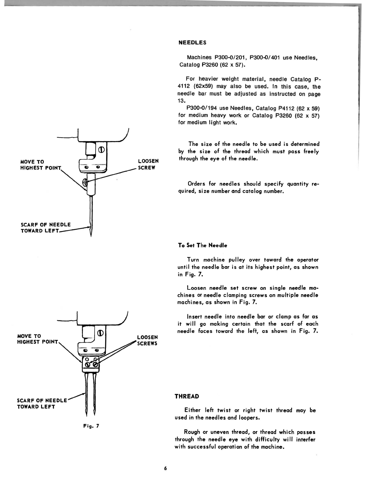
Needles
•.•....••..•.........•.••.••.....•••..
6
Setting
•...•.••.••..•..•........••••..•••..
6
Needle Bar, Height
•.•.••..•..•....•...••..••••
14
Needle Bar, Position
••.•.•...•....••.•...•••••
13
Needle Guard,
.•......•...••...•••.•..•..•••..
15
Presser
Bar, Height
•..••••.....•..•....•..••••
11
Presser
Foot, Pressure
......................
8, 9
Speed
•.•.•..••.•.....•.•.•••.•.•••...•••.••..
5
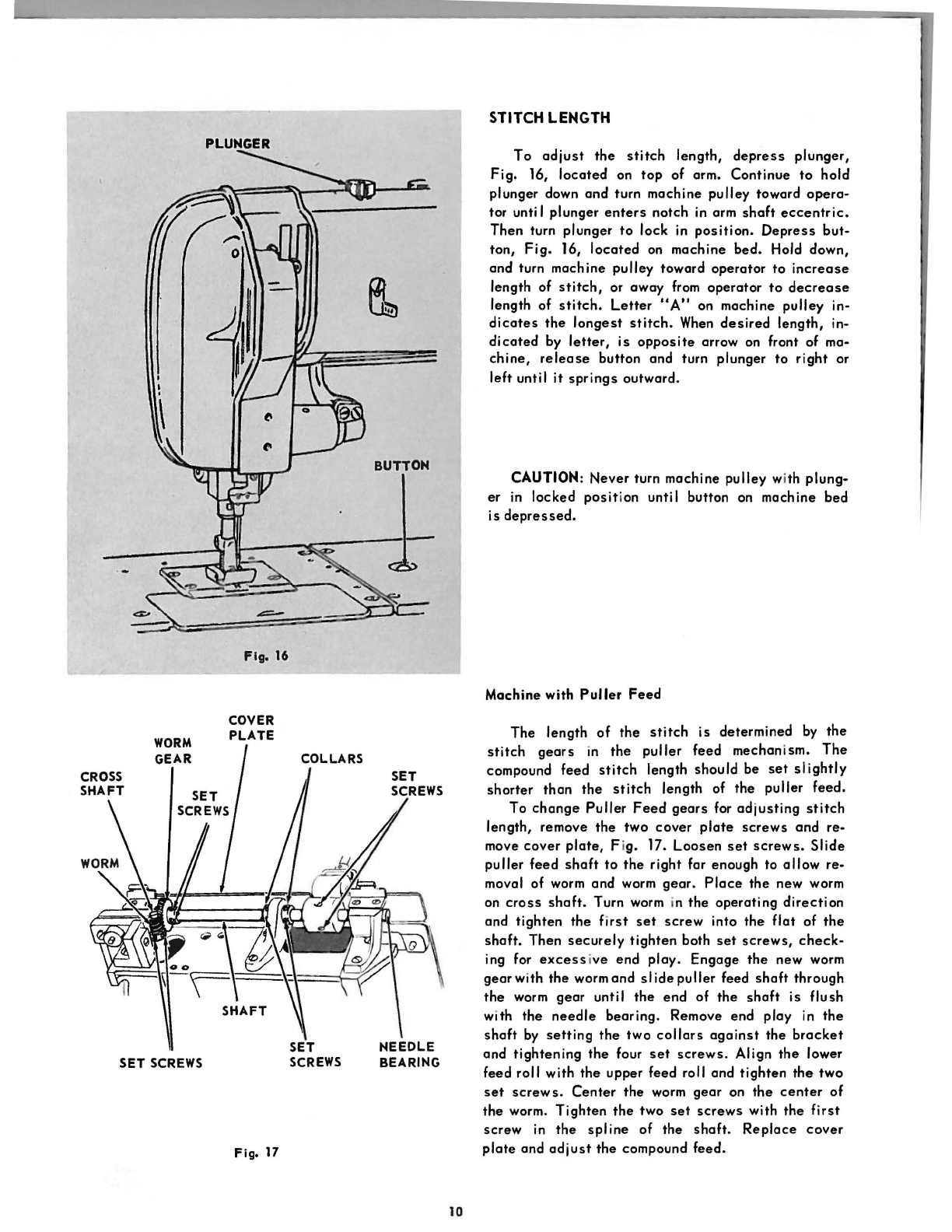
Stitch Length
.•.••..•..•.•..••.•..••.•••.•••.
.10
Spreader, Positioni
ng
••.•.•.....•••.•..••••••••
16
Lengthwise Setting
•.......•..•..•.•••..•••
16
Sidewise and Height Setting
..•...•......••••
16
Toke-up, Adjustment
.•..•..•.........••.•..•••
17
Looper Thread
.••.•..••.•.•.•••.•••.•.••••
17
Needle Thread
.•..••••....•.••.•...••..•••
17
Tension
.•..•.••.••....•..•....••.••.••.•.••.•
8
Releaser
...•.•..••.•.••..•.•..••..•.••.••
17
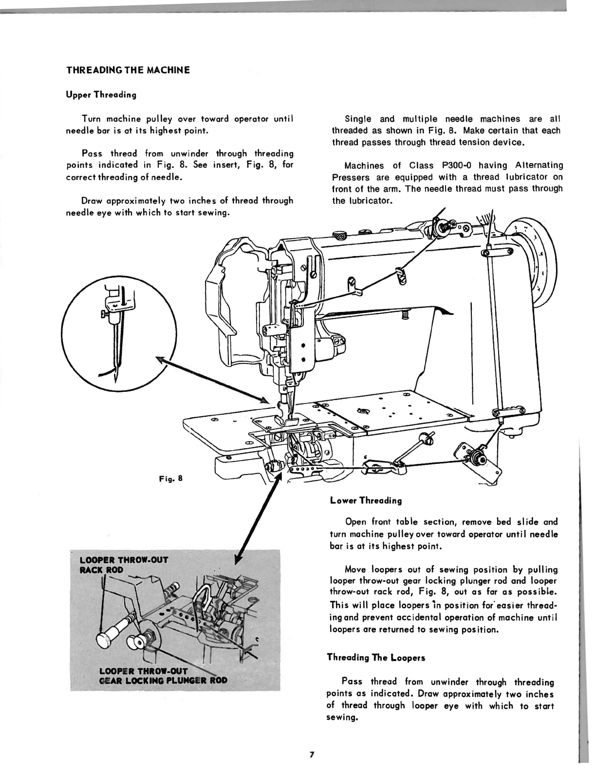
Threading
.•..•......••.•..•..••..••..••..••••
7
Upper
.•.....••.•.....•.....•.•..••.••.••••
7
Lower
••••.•••....••.••..••••••.••••...•••
7
From the library of: Superior Sewing Machine & Supply LLC