UNISource Corporation DM-1150B User manual

80000 Counts
Bench Digital Multimeter
Operation Manual V2.0
BENCHTOP INSTRUMENT
www.GlobalTestSupply.com
Find Quality Products Online at: sales@GlobalTestSupply.com

- 1 -
1. GENERAL
This meter is an intelligent and multi-functional device for various measurement. It features high quality, high
accuracy, high reliability, special high frequency measurement and low cost. The meter is in compliance with IEC
6010 CAT II 1000V and CAT III 600V high voltage standards. Other features of this instrument are listed below:
Multi-display: primary 80000 counts, secondary 80000 counts, bar graph 23 segments
50 measuring functions, with basic DCV, ACV, DCA, ACA, Ω, CAP, Hz, TEMP, diode and Continuity
measuring function, etc.
18 types of frequency, frequency up to 80MHz, 1800 waveform outputs, 0.1%~99% duty cycle.
Simultaneous measure (AC+DC), (AC+Hz), (DC+dBm), (dBm+Hz), (Hz+Duty), (℃+℉).
Auto data update and refresh, auto data hold, auto peak hold.
36-hour dynamic record: MAG, MIN, AVG, MAX-MIN (REL△), (REL%), setting upper & lower limit,
timing measurement
AC measuring adopts highly accurate true RMS measurement, with testing frequency bandwidth and
AC+DC measuring, capable of accurate true RMS measuring of any waveforms in AC range
RS-232 interface
SAFETY INSTRUCTIONS
High voltage GND Dual insulation Refer to manual.
WARNING! To avoid the electric shock and physical injury, and to avoid possible damage to the meter
and the tested equipments, read this operation manual carefully before using this meter, and follow the following
safety guidelines:
Before use, check and make sure that the instrument’s plastic chassis, the test leads and the insulation layer
are intact.
User the meter only as specified in this manual. Otherwise, the protection provided by the meter may be
expired.
Never measure voltage while the test leads are inserted into the current input terminals.
Do not use the meter if it looks damaged
Inspect the leads for damaged insulation or exposed metal, check test lead continuity. Replace damaged
leads.
Disconnect the power and discharge all high-voltage capacitors before testing in resistance, continuity and
diode function.
Be cautious when working at voltage above DC60V or AC42V. Such voltages may cause a shock hazard.
When undertaking measurement, keep your fingers behind the guard’s plant on the test leads or probes.
Select the proper function and range for measurement to avoid damage to the meter.
Disconnect the test leads from the test points before changing to another function.
The specifications are subject to change without notice.
The content of this manual is regarded as correct. If any error or omits is found, please contact with the
manufacturer.
We hereby will not be responsible for the accident and damage caused by improper operation.
The function stated for this User Manual cannot be the reason of special usage.
www.GlobalTestSupply.com
Find Quality Products Online at: sales@GlobalTestSupply.com

- 2 -
2. PANEL INSTRUCTIONS
Fig.2-1 Front panel
Fig. 2-2 Rear Panel
www.GlobalTestSupply.com
Find Quality Products Online at: sales@GlobalTestSupply.com

- 3 -
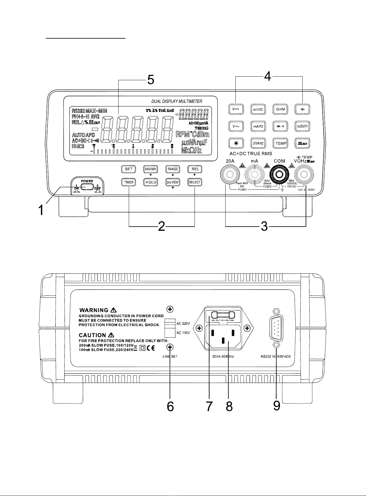
1. Power switch: turns the meter on or off
2. Auxiliary keys: SELECT, RANGE, SET, MAX/MIN, Timer/RS232/HOLD/2nd VIEW/ REL
△
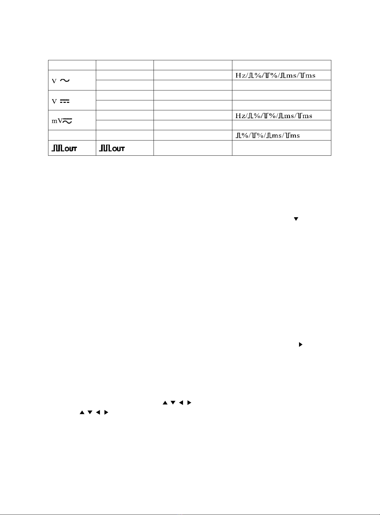
SELECT: Selects measurement mode
RANGE: Selects measurement range. The meter is default at auto range mode.
SET:
When the SET button is in operation, the RANGE button is used as a moving up button ( ), the 2nd VIEW
button as a moving down button ( ), the MAX/MIN as a moving left button ( ), and REL
△
as a moving
right ( ). In this case, the RANGE, 2nd VIEW, MAX/MIN and REL
△
buttons’ original functions are
disabled. buttons can be used to enter and adjust the setting values.
Press SET button for at least 2 seconds to start the backlight. Press this button again to turn off the backlight.
The backlight can auto off if this button is not engaged within 30 seconds.
MAX/MIN:
Presses this button to enter the dynamic record mode, with maximum record period of 36 hours.
In the dynamic record mode, the meter automatically records the maximum value (MAX), minimum value
(MIN), difference value (MAX-MIN) and calculate the average value (AVG) of all readings. Press this button
to cycle MAX, MIN, AVG, MAX-MIN on the secondary display.
Pressing this button for at least 2 seconds, the meter returns to auto range.
Timer/RS232:
TIME:
TIMER function is enabled only in the REL△andMAX/MIN measuring mode.
Press TIMER key to start the secondary display for counting time. Press TIMER key again to turn off the
counting time display.
When the secondary display is display counting time, press key SELECT to enter Beeper setup for setting up
a timer for beeper. Then, press key REL
△
( ), MIX/MIN ( ), RANGE ( ), 2nd VIEW ( ) to input the
time. Next press key TIMER to validate the new time data. When the counting time exceeds the preset time,
the beeper sounds.
In the above two modes, press key HOLD to stop timer function and turn off secondary display, but the
preset time remains unchanged.
The time is display in the format of 8.88.88 on the secondary display. The max.counting time is 9.59.59
RS232:
Pressing this button for at least 2 seconds, the RS232 remote control is enabled for PC control and
communication with other instruments. The LCD display “RS232’
Auto power off function is disabled in this RS232 programmable mode.
Pressing this button for at least 2 seconds again to exits this mode and return to normal mode.
HOLD:
Pressing this button, the meter enters auto data hold mode and “A-H” is displayed on the LCD.
The data hold mode allows users to hold the displayed value while the analog bar graph shows the current
reading.
Pressing this button again, the meter enters Peak+ hold mode and a “PH+” appears on the LCD display.
Pressing this button again, the meter enters Peak- hold mode and a “PH-” appears on the LCD display.
Pressing this button for at least 2 seconds, the meter exits HOLD mode and return to normal mode.
www.GlobalTestSupply.com
Find Quality Products Online at: sales@GlobalTestSupply.com

- 4 -
2nd VIEW: Selects the secondary display function. In various measuring mode, press 2nd VIEW button to cycle
the displayed data on secondary display. Se the follow table:
Function key
Measuring mode
Primary display
Secondary display
ACV+Hz ACV
AC dBm+Hz AC dBm ACV/Hz
(ACV+DCV)+Hz
ACV+DCV
ACV/Hz
dBm+Hz dBm Hz/ACV/DCV/ACV+DCV
ACmV+Hz ACmV
dBm+Hz dBm Hz/ACmV/DCmV/ACmV+DCmV
Hz/DUTY Hz Hz
Press key 2nd VIEW to
change output frequency
Press key SELECT to change
duty value
In square waveform output mode, press 2nd VIEW button to select frequency and trigger the square
waveform at the selected frequency:
0.5000Hz/1.0000Hz/2.0000Hz/10.00Hz/50.000Hz/60.240Hz/74.63Hz/100.00Hz/151.50Hz/200.00Hz/303.00
Hz/606.10Hz/1.2500kHz/1.6660kHz/2.5000kHz/5.0000kHz.
Press this key for at least 2 seconds to return to 606.10Hz, 50% duty output state.
When the SET button is in operation, 2nd VIEW button is using as a moving down button ( ). Pressing this
button moves the setting digit down
REL
△
:
Pressing this button, the meter enters relative measuring mode and “REL△” appears on the L CD display.
The relative measuring functions measures the difference between the testing value and the reference value.
The current readings on the secondary display are used as a relative value. The primary display displays the
relative measurement in two modes:
One is: REL△=measuring value – Reference value
The other is: REL%= (REL△/R eference val ue)x 100% (press SELECT button to select REL
△
or
REL% mode)
Press REL
△
button again, the testing value will be used as reference value and displayed on the secondary
display.
While the SET button is in operation, the REL
△
button is used as a moving right button ( ) to move the
setting digit to the right.
Press REL
△
for at least 2 seconds to exits reference mode and return to normal mode.
Set up reference value for measurement:
2. In every reference value, use RANGE button to select a proper range
3. When SET button is in operation, press SELECT button twice to set up reference value for
measurement. At the same time, the are enabled.
4. Use buttons to adjust the reference value.
Press SET button to validate the new setup.
3. Terminal
COM: Common terminal for all measurements
V Ω Hz: Volts, Ohn, Diode, Freq., Temp, and Cap. Measurement and square wave output terminal
mA: Milli ampere current measurement terminal
www.GlobalTestSupply.com
Find Quality Products Online at: sales@GlobalTestSupply.com

- 5 -
20A: Ampere current measurement terminal
4. Function Key
: ACV
: DCV
: DC/AC Milli voltage
: Diode & Continuity
Ω : Resistance
DUTY/Hz: Duty/Frequency
5. LCD Display: The following table gives description of the symbols displayed on the LCD.
Fig.2-3 LCD display
No. Symbol Description
1
Analog bar graph
2, 3, 17
Negative sign
4
Square wave output
5 Hi Hi frequency or thermocouple indicator
6
Low battery
7
Diode/Audible continuity function
8 REL△% Relative measurement
9, 19 DC, AC, DC+AC DC, AC, DC+AC voltage or current
10 PH+ PH- +Peak Hold, -Peak Hold
11 A-H Auto Hold
12 AV G Average reading
13
Auto
Auto mode
14 APO Auto power off sign
15 RS232 Communication on annunciation
16
MAX/MIN/MAX-MIN
MAX Rereading/MIN Reading/MAX-MIN Reading
20 mV/V/mA/A Voltage and current units on secondary display
21 Hz/kHz/MHz/Ω/kΩ/MΩ Frequency and resistance units on secondary display
22
Duty cycle unit and plus width unit
23 nF/μF Capacitance unit
24 mV/V/mA/A Voltage and current units on primary display
25 dBm dBm annunciation
26
Hz/kHz/MHz/Ω/kΩ/MΩ
Frequency and resistance units on primary display
27, 18 ℃ ℉ Temperature units and measurement indicator
28 RPM Round/per minute
www.GlobalTestSupply.com
Find Quality Products Online at: sales@GlobalTestSupply.com

- 6 -
6. AC110V/220V selector switch
7. Fuse
8. Power plug
9. RS232 interface
3. SPECIAL FUNCTIONS
3.1 Auto Power Off
The meter has two power off function. In normal conditions when the meter is power on, if there is no operation
on any of the buttons or function keys within 30 mints, the meter will be automatically powered off. Five mints
before auto power off, the audible five beepers give indication that the meter is gong to be power off.
3.2 Setting Upper and Lower Limits for Measurement
The upper and lower measurement limits can be set up in the following steps:
1. Set the upper limit: power on the meter select range press SET button press SELECT button to
start the upper setting mode (“ ” appears on secondary display) press buttons to adjust
the value press SET button to validate the new input.
2. Set the lower limit: power on the meter select range press SET button press SELECT button to
start the lower setting mode (“ ” appears on secondary display) press buttons to adjust
the value press SET button to validate the new input.
3. After setting up the upper and lower limits, measurement can be carried out and the LCD will have 3 kinds of
displays to the results:
a) If the measuring value exceeds the upper limit, the LCD displays the measuring value on the primary
display and “ ” on the secondary display.
b) If the measuring value exceeds the lower limit, the LCD display the measuring value on the primary
display and “ ” on the secondary display.
c) If the measuring value is between and upper and lower limit, the LCD displays the measuring value on
the primary display and “ ” on the secondary display.
3.3 Set up the Time for Measurement
1. Press TIMER button to set enter the setup of time. The secondary display displays “0.00.00”
2. Press SELECT button and the last digit of “0.00.00” on the secondary display glitters, which means this digit
can be adjusted. Use the buttons to adjust the digit value. (The first digit from the left is hour, the
second and third are minute, the fourth and fifth are second.)
3. Press TIMER button to validate the new setup. By now the measuring time is set.
3.4 Analog Bar Graph
The function of analog bar graph is imitating the analog needle of the meter but without the overshoot. The bar
graph refreshes data 40 times per second. Because the graph responds 10 times faster than the digital display, it is
widely used in the application of peak value test and zero calibration. It is also commonly used in observing the
rapid variation of input signals. The bar graph has 23 segments. The number of lit segments is relative to the
full-scale value of the selected range. One unit of the bar graph represents 4000 counts/bar except when in the
relative mode. The polarity is indicated at the left of the bar graph.
3.5 Square Wave Output
The square wave output is a very useful function. With adjustable square wave frequency and duty cycle, users
can carry out the pulse wave modulation (PWM) output, and adjust the voltage control, timer control and clock
www.GlobalTestSupply.com
Find Quality Products Online at: sales@GlobalTestSupply.com

- 7 -
syntherization.
3.6 Measurement Range
A measurement range determines the measuring limits. The meter has several measurement ranges.
1) Select a proper measurement range:
If the selected measurement range is too small (the testing signal exceeds the measurement range), the
meter will display “OL” on the LCD.
If the selected measurement range is to large, the testing results may have a relatively low resolution.
2) Auto range and Manual range
The meter has both auto range and manual range for the measurements.
In the AUTO measuring mode, the meter will automatically select a most suitable range for the testing
signal. In AUTO mode, the meter will display “AUTO” on the LCD.
In the MANUAL measuring mode, the measuring range is selected manually by pressing RANGE
button.
If there is more than one range in a measuring function, the meter will default in AUTO range. This
allows users to override the auto range and lock the meter in a specific range.
In HOLD or MAX/MIN recording mode, changing the measurement range manually will automatically
exit the HOLD or MAX/MIN mode.
3) Enter or exit mauran range mode
Press RANGE button to select manual range mode. Then, every press on the RANGE button, the meter
steps to a higher range and will return to the lowest range when the higher range is stepped into.
Pressing RANGE button for at least two seconds can also return to auto range mode.
4. OPERATION INSTRUCTIONS
4.1 DC Voltage Measurement (DCV)
The measurement of DC voltage has three modes: DCV,
DCV+ACV and dBm.
Set the function key to “ ” position.
Press SELECT button to select measurement mode.
According to practical demands, press REL
△
, MAX/MIN
and 2nd VIEW buttons to have relative measuring or
record.
Connect the black test lead to “COM” terminal and the read
test lead to “V Ω Hz” terminal.
The meter is in auto range mode and will automatically
select a most suitable range. To select a range manually for
DCV measurement, press RANGE button to select a proper range. There are four ranges to choose from:
8.0000V/80.000V/800.00V/1000.0V
Touch the test leads to the test points and read the display on both the primary and secondary display.
Press SELECT
Primary display
Secondary display
Press 2nd VIEW
DCV
DCV
DCV+ACV
DCV
dBm
dBm
Hz/ACV/DCV/DCV+ACV
www.GlobalTestSupply.com
Find Quality Products Online at: sales@GlobalTestSupply.com

- 8 -
NOTE:
1. In dBm measurement mode, the decimal point of dBm is fixed between the second and third digits.
2. When in dBm measurement, the impedance is default at 600Ω. To change the impedance, press RANGE
button to select a proper impedance. The impedance can be chosen from:
4/8/16/32/50/75/93/110/125/135/150/200/250/300/500/600/800/900/1000/1200Ω.
4.2 AC Voltage Measurement (ACV)
WANRNING: The testing AC voltage must not exceed AC750V!
The measurement of AC voltage has three modes: ACV,
ACV+Hz and dBm.
Set the function key to “ ” position.
Press SELECT button to select measurement mode.
According to practical demands, press REL
△
, MAX/MIN
and 2nd VIEW buttons to have relative measuring or
record.
The meter is in auto range mode and will automatically
select a most suitable range. To select a range manually for
ACV measurement, press RANGE button to select a proper
range. There are three ranges to choose from:
8.0000V/80.000V/750.00V
Connect the black test lead to “COM” terminal and the read test lead to “V Ω Hz” terminal.
Touch the test leads to the test points and read the display on both the primary and secondary display.
Press SELECT
Primary display
Secondary display
Press 2nd VIEW
ACV
ACV
ACV+Hz
ACV
dBm
dBm
Hz/ACV
NOTE:
1. In dBm measurement mode, the decimal point of dBm is fixed between the second and third digits.
2. When in dBm measurement, the impedance is default at 600Ω. To change the impedance, press RANGE
button to select a proper impedance. The impedance can be chosen from:
4/8/16/32/50/75/93/110/125/135/150/200/250/300/500/600/800/900/1000/1200Ω.
4.3 AC/DC Milli Voltage Measurement (ACmV, DCmV)
The measurement of AC/DC milli voltage have three modes:
D C m V, ACmV+Hz and dBm.
Set the function key to “ ” position.
Press SELECT button to select measurement mode.
According to poetical demands, press REL
△
, MAX/MIN
and 2nd VIEW buttons to have relative measuring or
record.
The meter is in auto range mode and will automatically
select a most suitable range. To select a range manually for
www.GlobalTestSupply.com
Find Quality Products Online at: sales@GlobalTestSupply.com

- 9 -
the measurement, press RANGE button to select a proper range. There are two ranges to choose from:
80.000mV/800.00mV
Connect the black test lead to “COM” terminal and the read test lead to “V Ω Hz” terminal.
Touch the test leads to the test points and read the display on both the primary and secondary display.
Press SELECT
Primary display
Secondary display
Press 2nd VIEW
DCmV
DCmV
ACmV+Hz
ACmV
dBm
dBm
Hz/ ACmV/ DCmV/ DCmV+ ACmV
NOTE:
1. In dBm measurement mode, the decimal point of dBm is fixed between the second and third digits.
2. When in dBm measurement, the impedance is default at 600Ω. To change the impedance, press RANGE
button to select a proper impedance. The impedance can be chosen from:
4/8/16/32/50/75/93/110/125/135/150/200/250/300/500/600/800/900/1000/1200Ω.
3. In dBm measurement mode, REL△, MAX/MIN, AVG, A-H functions are disabled.
4. In milli voltage measurement mode, in order to obtain DC+AC function, the input terminal of ADC does not
employ coupling capacitor. Therefore, never apply a voltage over double value of DC or AC voltage of the
rated value of this range.
4.4 AC/DC Milli Current Measurement (ACmA, DCmA)
WANRNING:
To avoid injury and damage to the meter, never attempt an in-circuit current measurement when the
fuse is blown, or when the voltage between open circuit and the ground is 1000V.
To avoid damage to the meter, check the meter’s fuse before proceeding.
Before current measurement, turn of the circuit power supply, discharge the high voltage capacitance.
Under no circumstances, do not test the voltage when the test leads are plugged in “mA” or “20A”
terminals.
Do not place the probes in parallel with a circuit or
component when the leads are plugged into the current
terminals.
The measurement of AC/DC milli current has three modes:
DCmA, ACmA, DCmA+ACmA, and ACmA +Hz
Set the function key to “mA ” position.
Press SELECT button to select measurement mode.
According to practical demands, press REL
△
, MAX/MIN
and 2nd VIEW buttons to have relative measuring or
record.
The meter is in auto range mode and will automatically
select a most suitable range. To select a range manually for the measurement, press RANGE button to select
a proper range. There are two ranges to choose from: 80.000mA/800.00mA
Connect the black test lead to “COM” terminal and the read test lead to “mA” terminal.
Break the circuit path to be tested. Tough the black test leas to the negative of the break and the red test lead
to the positive of the break. Read the display.
After finishing measurement, disconnect the power supply to the circuit and discharge all high voltage
www.GlobalTestSupply.com
Find Quality Products Online at: sales@GlobalTestSupply.com

- 10 -
capacitors. Remove the meter and restore the circuit to normal operation. Pull out the test lead from “mA”
terminal.
Press SELECT
Primary display
Secondary display
Press 2nd VIEW
DCmA
DCmA
ACmA
ACmA
DCmA+ ACmA
DCmA+ ACmA
ACmA
AcmA+Hz
ACmA
Hz
4.5 AC/DC Current Measurement (ACA, DCA)
The measurement of AC/DC current has four modes: DCA, ACA, DCA+ACA, and ACA +Hz
Set the function key to “A ” position.
Press SELECT button to select measurement mode.
According to poetical demands, press REL
△
, MAX/MIN and 2nd VIEW buttons to have relative
measuring or record.
The meter is in auto range mode and will automatically select a most suitable range. To select a range
manually for the measurement, press RANGE button to select a proper range. There are two ranges to
choose from: 8.0000A/20.000A
Connect the black test lead to “COM” terminal and the read
test lead to “20A” terminal.
Other operations apply the same as explained in section 4.4
Press SELECT
Primary display
Secondary display
Press 2nd VIEW
DCA
DCA
ACA
ACA
DCA+ACA
(DC+AC)A
ACA
ACA+Hz
ACA
Hz
4.6 Resistance Measurement (Ω)
WANRNING: To avoid damage to the meter or the testing equipments disconnect circuit power and
discharge all high voltage capacitors before measuring resistance. Use the DC function to confirm that the
capacitor is discharged.
NOTE: In measuring low resistance, the resistance of the test leads may cause an error of 0.1Ω~0.5Ω in the test
results. To avoid this error, first short the test leads, next press REL
△
button. The primary display will be null
and the secondary display displays the resistance of test lead.
Measure the to-be tested resistance and the result will be
displayed on the primary display.
The measurement of resistance has three modes: normal,
continuity and Hi resistance. Press SELECT button to choose
from these modes.
Normal mode
Set the function key to “Ω” position
According to practical demands, press REL
△
, MAX/MIN
and 2nd VIEW buttons to have relative measuring or
www.GlobalTestSupply.com
Find Quality Products Online at: sales@GlobalTestSupply.com

- 11 -
record.
The meter is in auto range mode and will automatically select a most suitable range. To select a range
manually for the measurement, press RANGE button to select a proper range. There are six ranges to choose
from: 800.00Ω/8.0000kΩ/80.000kΩ/800.00kΩ/8.0000MΩ/80.000MΩ
Connect the black test lead to “COM” terminal and the read test lead to “VΩ Hz” terminal.
Touch the probes to the test points and read the display.
Measurement mode
Primary display
Secondary display
Ω Ω/kΩ/MΩ MAX/MIN, REL△parameters
Continuity mode
Press SELECT button to select “ ” range.
If the testing points resistance falls below 50Ω. The beeper will sound.
Hi resistance
This function is used to measure the resistance above 80MΩ.
Press SELECT button to select “HiΩ” range. The primary display will display “Hi”.
A single range is 8000.0MΩ. If the testing points resistance falls below 10MΩ and above 8000.0MΩ, “OL”
will appears on the display.
4.7 Capacitance Measurement (CAP)
WANRNING: To avoid damage to the meter or the testing equipments disconnect circuit power and
discharge all high voltage capacitors before measuring capacitance. Use the DC function to confirm that the
capacitor is discharged.
NOTE:
Some capacitors have polarities. In measuring polarities capacitors, touch the red test lead to the positive
polarity and the black test lead to the negative polarity.
In measuring low capacitance, the resistance of the test leads may cause an error in the test results. To avoid
this error, first short the test leads, next press REL
△
button. The primary display will be null and the
secondary display displays the resistance of test lead. Measure the to-be tested resistance and the result will
be displayed on the primary display.
Capacitor is capable of storing electric charge. When testing capacitance, only the value on a stable display is the
correct result.
Set the function to “ ” position.
According to practical demands, press REL
△
, MAX/MIN and 2nd VIEW buttons to have relative
measuring or record.
The meter is in auto range mode and will automatically
select a most suitable range. To select a range manually for
the measurement, press RANGE button to select a proper
range. There are six ranges to choose from:
1.0000nF/10.000nF/100.00nF/1.0000μF/10.000μF/100.00μF
Connect the black test lead to “COM” terminal and the red
test lead to “VΩ Hz” terminal.
Touch the probes to the test points and read the display.
www.GlobalTestSupply.com
Find Quality Products Online at: sales@GlobalTestSupply.com

- 12 -
Measurement
mode
Primary display
Secondary display
CAP
nF/μF
MAX/MIN, REL
△parameters
4.8 Frequency (Hz) and Rotation Speed Measurement (RPM)
The measurement of frequency and rotation speed measurement
have three modes: normal, Hi Hz and RPM.
Set the function key to “Hz” position.
Press SELECT button to select measurement mode.
The meter is in auto range mode.
Normal mode
In normal mode, the frequency testing range is
0.5Hz~8.0000MHz, divided into six ranges:
999.99Hz/9.9999kHz/9.999kHz/999.99kHz/8.0000MHz.
The meter is in auto range mode and will automatically
select a most suitable range. To select a range manually for
the measurement, press RANGE button to select a proper range from the six ranges.
Touch the probes to the signal source and read the display.
Measurement
mode
Primary display
Secondary display
Press 2nd VIEW
Hz
Hz/kHz/MHz
High frequency mode (Hi Hz)
In Hi Hz mode, the frequency testing range is
8MHz~1000MHz, divided into four ranges:
8.0000MHz/80.000MHz/800.00MHz/1000.0MHz. Use the
high frequency accessories to measure frequency above
10MHz.
The meter is in auto range mode and will automatically select
a most suitable range. To select a range manually for the
measurement, press RANGE button to select a proper range
from the six ranges.
Touch the probes to the signal source and read the display.
Measurement mode
Primary display
Secondary display
HiHz
00000
00000MHz
NOTE:
1. The primary and secondary displays are using together to form a 10-digit display. The primary display
displays the higher 5 digits while the secondary display displays the lower 5 digits.
2. In high frequency measurement, a high frequency tuner is required to facilitate the measurement
www.GlobalTestSupply.com
Find Quality Products Online at: sales@GlobalTestSupply.com

- 13 -
RPM Measurement
In RPM mode, the testing range is 0~99999RPM, accuracy
±(0.05% of reading+5). Use the RPM accessory to test the
rotation speed and read the display.
Measurement mode
Primary display
Secondary display
RPM
RPM
No display
4.9 Temperature Measurement (TEMP)
The measurement of temperature has two modes: normal and Hi.
Measuring range: -50℃~1300℃, -58℉~2372℉
Display: Primary ℃, Secondary ℉
Set the function to “TEMP” position.
Press SELECT button to select Hi or normal mode.
In Hi mode, use K type thermocouple to measure temperature.
Press SELECT again, “Hi” disappears from the display, and the
displayed temperature is internal temperature of the meter.
Connect the black test lead to “COM” terminal and the red test
lead to “VΩ Hz” terminal. Read the display.
4.10 Diode and Continuity Check
WANRNING: To avoid damage to the meter or the testing equipments disconnect circuit power and
discharge all high voltage capacitors before measuring. Use the DC function to confirm that the capacitor is
discharged.
Set the function to “ ” position.
Connect the black test lead to “COM” terminal and the red
test lead to “VΩ Hz” terminal.
For diode check, touch the red test lead to the positive
polarity of the diode and the black test lead to the negative
polarity. Touch the probes to the test points and read the
display.
For continuity check, the beeper sounds if the resistance
falls below 60Ω
4.11 Square Wave Output
The meter can be used as a square waveform generator, output the waveform with frequency range of
0.5Hz~5000Hz.
Set the function key to “ ” position. The square waveform will be output on “COM” and “VΩ Hz”
terminals.
The output square waveform is default at 606.1Hz, duty cycle 50%
www.GlobalTestSupply.com
Find Quality Products Online at: sales@GlobalTestSupply.com

- 14 -
Connect the black test lead to “COM” terminal and the red test
lead to “VΩ Hz” terminal.
Press 2nd VIEW button to select the frequency from the
following ranges:
0.5000Hz/1.0000Hz/2.0000Hz/10.000Hz/50.000Hz/60.240Hz/74.
63Hz/100.00Hz/151.50Hz/200.00Hz/303.00Hz/606.10Hz/1.2500
kHz/1.6660kHz/2.5000kHz/5.0000kHz
Press SELECT button to select the duty cycle from 1% to 99%
Press 2nd VIEW button for at least 2 seconds to return to default
square wave output.
Function
Primary display
Press 2nd VIEW
Secondary display
Press SELECT
Hz
4.12 Backlight Display
Press “ ’ button to turn on backlight. Press it again to turn it off.
5. PROGRAMMABLE CONTROL
The unit is equipped with RS232 interface and relevant software, which allows easy connections to PC for PC
control.
Software operating environment: Windos9x/NT/2000/XP
Software version: V1.0
5.1 Installation
Plug the CD disk into the CD drive. Start up the setup.exe file to install the software. Select a desired installation
path.
5.2 RS232 Port Set
RS232 port is used for the data transfer between the multimeter and PC. There are two ports to be chosen from:
COM1 and COM2.
5.3 Connect
Click “Connect” to activate the communication between the multimeter and PC. To disconnect the communication,
click “Disconnect”.
5.4 Recording Size
User can store up to 8192 files to the multimeter memory。
5.5 Sampling Interval
The sampling interval can be set at any value between 0.1~99 seconds.
5.6 Alarm Setup
This function sets the upper and lower limits for alarm. If the testing results exceed the preset upper or lower
limits, the PC will send out alarm with sound.
www.GlobalTestSupply.com
Find Quality Products Online at: sales@GlobalTestSupply.com

- 15 -
5.7 Auto Schedule
In this function, user can set up the start and end time of recording.
5.8 Open File
This function opens the stored files (History.txt), which include text file and graph file. The files can be renamed
or printed out. Move the mouse to the graph area; click the right key to display details.
5.9 Exit
Exit the current system.
5.10 Digital Display Window
The digital display window displays exactly the same contents as the multimeter LCD display does. However, the
digital display window on the PC gives you an easier view.
5.11 Push Button Panel
Basically, the buttons on this panel function the same as the buttons on the multimeter. Double click on the button
functions the same as pressing the multimeter button for 2 seconds.
5.12 Analog Display Window
The analog display window displays exactly the same as the analog display area of the multimeter LCD display.
The function and range parts display the current communication status, which allows users understand the
millimeter’s working state.
When the value is positive, the analog needle turns to green; while the value is negative, the needle turns to blue.
When the value is close to zero, the needles changes between yellow and red colors.
www.GlobalTestSupply.com
Find Quality Products Online at: sales@GlobalTestSupply.com

- 16 -
5.13 Real-time Graph Window
Before applying this function, user must choose a desired measuring range. The X axis indicates system time,
while the Y axis indicates the range of testing data.
5.14 Recorder Control Panel
In this panel function, user can set up the recording time, max.and min. values. The Start, Stop and Reset buttons
are used to control the data recorder. Click Start button to start the data recording and Stop button to stop the data
recording. In the meanwhile, the data has been stored in the History.txt file.
Click the Reset button to clear the current data in History.txt file, and get ready for the next data recording.
Recorder, Record time and Record in the bottom part of the panel indicate the current status of the data recorder.
Battery indicates the power supply status of the multimeter. If power supply is in good status, it will display
“Battery: High”. Otherwise, it will display “Battery: Low”.
In the right corner of the bottom displays the system time.
Should you have any questions regarding this software or any suggestions to us, please write down and inform us.
We will do the utmost to improve the software.
6. SPECIFICATIONS
6.1 Electrical Specifications
The accuracy is specified for one year after calibration at operating temperature of 18℃ to 28℃, with humidity at
0%~75%.
Accuracy specifications take the form of: ±(a% of reading+number of least significant digits).
Table1. DCV
Range
Resolution
Accuracy
Remarks
80mV
1μV
±(3% rdg+10)
Input impedance:
80mV~800mV: >1000MΩ
8V~1000V: 10MΩ
800mV 10μV
±(0.05% rdg+5)
8V 0.1mV
80V
1mV
800V
10mV
±(0.08% rdg+10)
1000V
0.1V
www.GlobalTestSupply.com
Find Quality Products Online at: sales@GlobalTestSupply.com

- 17 -
Table 2. ACV (True RMS)
Range
Resolution
Accuracy
80mV 1μV <75% Range: 50Hz~20kHz <75% Range: 20kHz~50kHz >75% Range: 50Hz~20kHz
800mV
10μV
±(0.8% rdg+50) ±(6.0% rdg+50) ±(8.0% rdg+50)
8V
0.1mV
80V
1mV
750V
10mV
50Hz~1kHz: <90% Range ± (0.8% rdg+50); >90% Range: ± (5.0% rdg+50)
Remarks: Input impedance: 80mV~800mV: >1000MΩ; 8V~1000V: 10MΩ. Parallel capacitance: <100pF
Table 3. DCA
Range
Resolution
Accuracy
Remarks
80mA
1μA
±(0.2% rdg+10) Fuse: F750Ma/250v F13A/250V
Voltage drop: ≤800mV
Max.input current: 20A (up to15 seconds)
800mA
10μA
8A 0.1mA ±(0.5% rdg+10)
20A
1mA
Table 4. ACA (True RMS)
Range Resolution Accuracy Remarks
80mA
1μA
50Hz~5kHz
±(0.2% rdg+10) Fuse: F750Ma/250v F13A/250V
Voltage drop: ≤800mV
Max.input current: 20A (up to15 seconds)
800mA
10μA
8A
0.1mA
50Hz~500Hz
±(0.5% rdg+10)
20A
1mA
Table 5. dBm
Function
Range
Accuracy
Resolution
dBm
-80.00dBm~+80.00dBm
±1.0% rdg
0.01dBm
Table 6. Resistance (Ω)
Range
Resolution
Accuracy
Remarks
800Ω
0.01Ω
±(0.3% rdg+10)
Overload protection:
250V RMS
8kΩ
0.1Ω
±(0.3% rdg+5)
80kΩ
1Ω
800kΩ 10Ω
8MΩ 100Ω
80MΩ 1kΩ 0Ω~40MΩ: ±(2.5% rdg+10)
40MΩ~80MΩ: ±(3.5% rdg+10)
Table 7. Frequency (Hz)
Range Accuracy Resolution Remarks
999.99Hz
±(0.5% rdg+5)
0.01Hz
Overload protection: 250V RMS
Sensitivity: 0.7V RMS
9.9999kHz 0.1Hz
99.999kHz 1Hz
999.99kHz
10Hz
8.0000MHz 100Hz
10.0MHz
±(0.1% rdg+5)
1kHz
Plus adapter
100.0MHz
10kHz
1000.0MHz 100kHz
www.GlobalTestSupply.com
Find Quality Products Online at: sales@GlobalTestSupply.com

- 18 -
Table 8. Capacitance
Range Resolution Accuracy Remarks
1nF 1pF ±(5.0% rdg+50)
Overload protection: 250V RMS
10nF
10pF
±(2.5% rdg+50)
100nF 100pF
1μF 1nF
10μF
10nF
100μF
100nF
Table 9. Diode
Range Accuracy Resolution Remarks
3.0000V ±(3.0% rdg+5) 0.0001V
Diode positive voltage drop
Overload protection: 250V RMS
Table 10. Square Wave Output
Description
Voltage amplitude Approx.3V
Frequency 0.5Hz~5000Hz
Duty cycle 1%~99%
Table 11. Temperature
Range Accuracy Resolution Remarks
-50℃~1300℃ ±(1.5% rdg+10) 0.1℃ K type thermocouple
Overload protection: 250V RMS
-58℉~2372℉ 0.1℉
6.2 General Specifications
Max.voltage between terminal and ground: 1000V RMS
Continuity beeper: Approx.3kHz
Display: dual display 80000, update 4 time/Sec.
Bar graph: 23 segments, update 40 time/Sec.
Electromagnetic compatibility:
For all ranges and functions (except capacitance), in a RF field of 1V/m, total accuracy=specified
accuracy+5% of range.
In a RF field, the capacitance has no specified range.
or all ranges and functions, in a RF field above 1V/m, there is no specified range.
Safety/Compliance: IEC 61010 CAT II 1000V, and CAT III 600V
Input voltage: AC110V/220V selectable, 50/60Hz
Operating environment: temperature 0℃~50℃, altitude below 2000m
Storage environment: temperature -20℃~60℃, altitude below 5000m
Relative humidity: ≤75%, at 0℃~40℃; ≤45%, at 40℃~50℃
Dimension: 260x220x82mm
Weight: Approx.1.4KG
Accessories:
Manual: 1pcs
Test lead: 1pcs
K type thermocouple: 1pcs
RS232 package: 1set
www.GlobalTestSupply.com
Find Quality Products Online at: sales@GlobalTestSupply.com

- 19 -
7. MAINTENACE
The meter is a precise and intelligent instrument. It has been accurately calibrated in the factory before shipment.
Readjustment is recommended only if repairs have been made in a circuit affecting adjustment accuracy or if you
have a reason to believe the unit is out of adjustment.
The following instructions are for use by qualified personnel only. To avoid electrical shock, do not perform any
servicing other than contained in the operating instructions unless you are qualified to do so.
Do not verify the circuit to avoid damaging. Power fuse: 200mA/250V (located in input power socket); Fuse for
measuring current: 800mA/250V (located in the current input terminal), 13A/250V (located the main circuit). The
fuse must be replaced by qualified personnel.
NOTE:
Do not connect the voltage higher than DC1000V or AC 1000V rms.
Do not measure voltage at the Ω range.
When replacing fuse, please take away the test leads from the measuring point and power off at first.
Keep the instrument away from water, dust and shock.
Do not operate the meter in high temperature or strong magnetic place.
Do not use the abrasives or solvents to clean the meter.
7.1 Fuse replacement
NOTE: Please select fuse of the same specification to replace it.
Power fuse: 200mA/250V (located in input power socket); Fuse for measuring current: 800mA/250V (located in
the current input terminal), 13A/250V (located the main circuit).
1. Te st fuse replacement:
Press the function key to Ω range
Connect a test lead to “VΩHz” terminal, use the pen tip to touch the “mA” or “20A” terminal to test the
resistance of the fuse
If the tested fuse resistance is below 5Ω, it means the fuse is good.
If the tested result is “OL” (over load), the fuse needed to be replaced.
If the fuse is tested as good but the multimeter cannot carry measurement, please send the multimeter for
repair.
2. Fuse replacement
Disconnect the multimeter from AC power source, and take off all test leads.
2A fuse replacement
Press “mA” input jack by finger; take out the fuse jack after turning 90°angle anti-clockwise
Take off the fuse, and replace an equivalent then turn on the fuse jack.
After press the fuse into the fuse jack, turn 90°angle by an inverse hour direction.
13A fuse replacement (must be replaced by qualified personal.)
Screw off the four screws on the button shell by a screwdriver, take off the upper shell.
Take off the fuse, and replace an equivalent then turn on the fuse jack.
Take on the shell, .Screw on the four screws on the button shell by a screwdriver.
www.GlobalTestSupply.com
Find Quality Products Online at: sales@GlobalTestSupply.com
Table of contents
Other UNISource Corporation Multimeter manuals