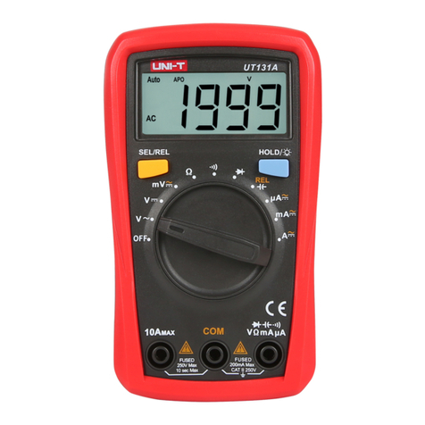
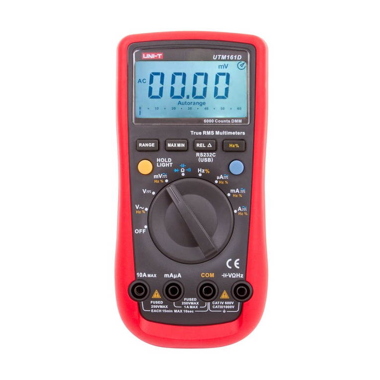
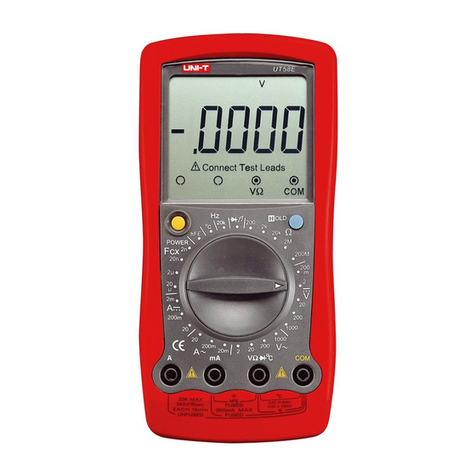
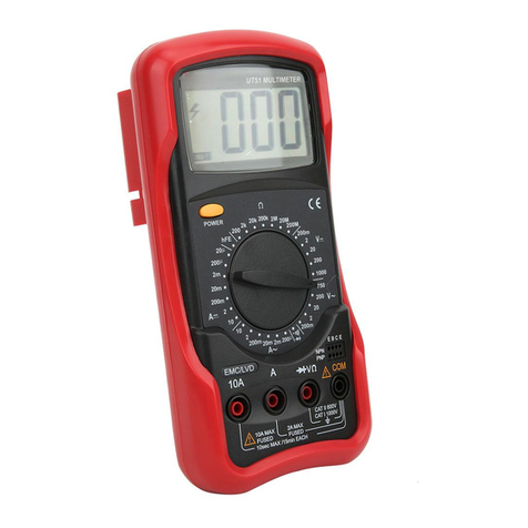
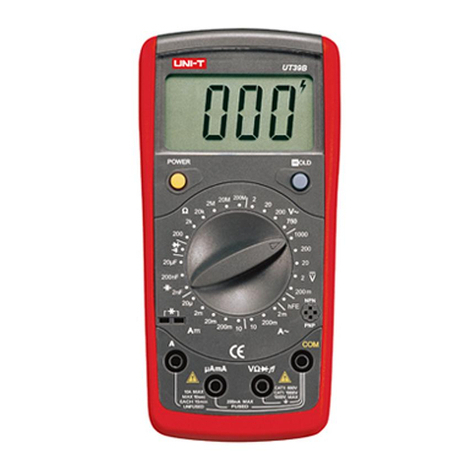
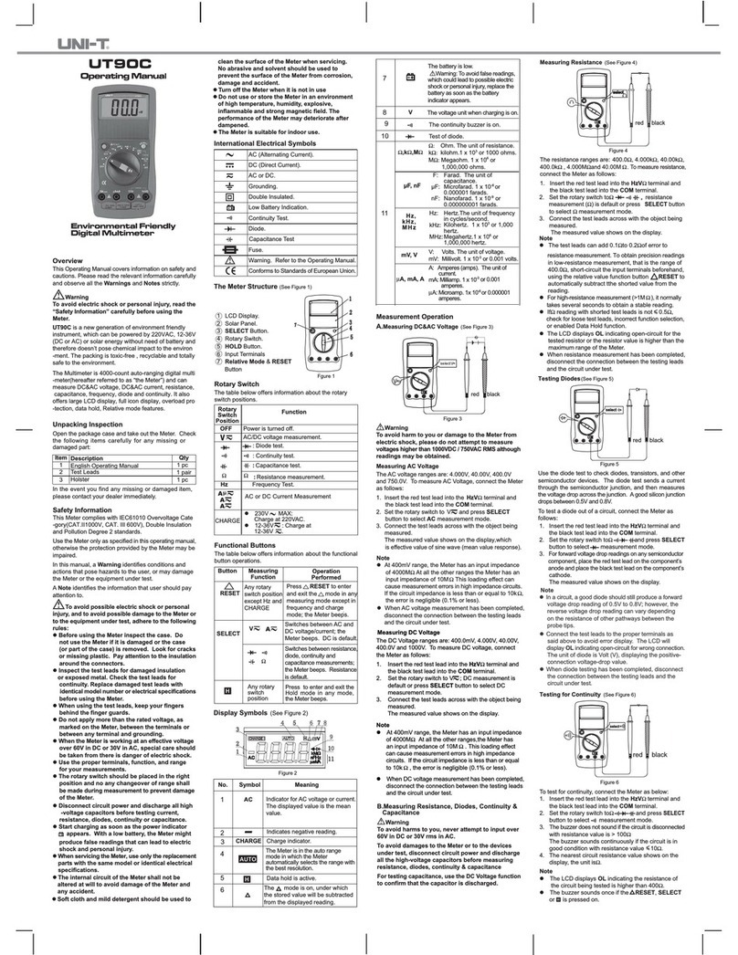
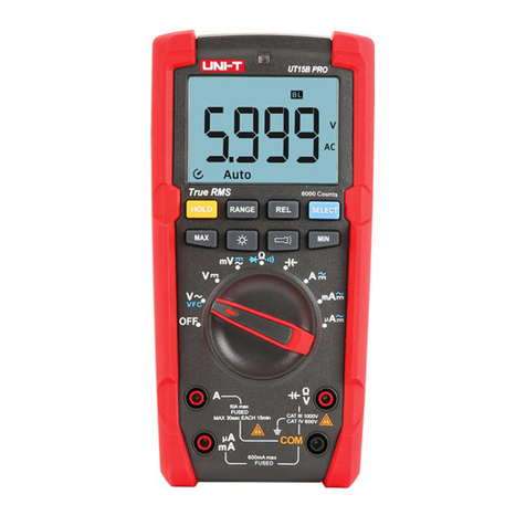
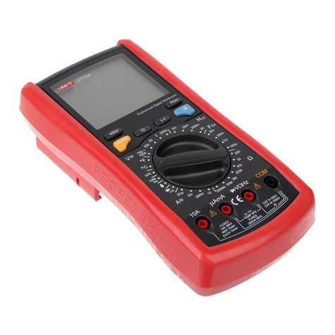
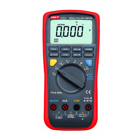
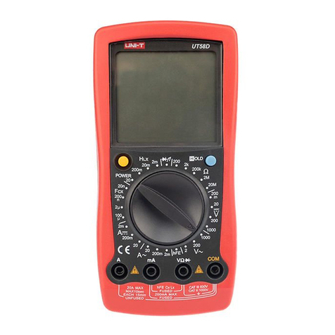
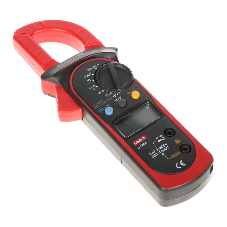
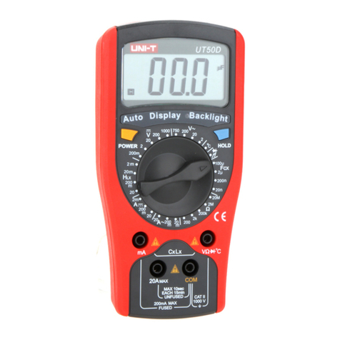
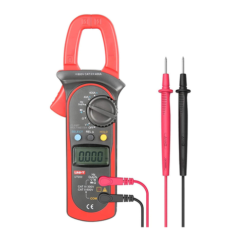
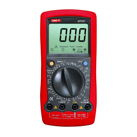
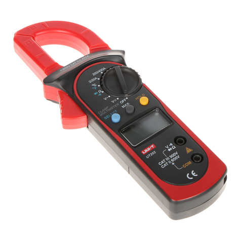
Unit UT61B User manual

®
UT61B
MANUAL
HANDLEIDING
MODE D’EMPLOI

®
1
UT61B MODERN DIGITAL MULTIMETER
• Illustrations and tables 1
• English Operating Manual 6
• Nederlandse handleiding 16
• Mode d’ emploi français
ILLUSTRATIONS
FIG 2: voltage measurement
FIG 7: Capacitance measurement
FIG 3: AC/DC
current Measurement
FIG 4: Resistance Measurement FIG 5: Diode measurement FIG 6: Continuity measurement
FIG 8: Frequency measurement
FIG 1: The meter’s structure
FIG 9: Temperature measurement

Model: UT61B MANUAL
2
DC VOLTAGE
Range Resolution Accuracy
40mV 0,01mV +/-(0.8%+3)
400mV 0.1mV
4V 0.001V
+/-(0.5%+1)40V 0.01V
400V 0.1V
1000V 1V +/-(1.0%+3)
AC VOLTAGE
Range Resolution Accuracy
40mV 0.01mV +/-(1.2%+5)
400mV 0.1mV
+/-(1.0%+3)
4V 0.001V
40V 0.01V
400V 0.1V
750V 1V +/-(1.2%+5)
TABLES
Accuracy: +/-(a% reading + b digits) - guaranteed for 1 year
Operating temperature: 23°C +/- 5%
Relative Humidity: < 75%
Input impedance (400mV): > 3000Mall other range: 10M
Maximum input voltage: 1000V DC
Input impedance (400mV): > 3000Mall other range: 10M
Maximum input voltage: 750V AC
Displays effective value of sine wave.
mv range is applicable from 5% of range to 100% of range.

®
DC CURRENT
Range Resolution Accuracy Overload
protection
400µA 0,1µA +/-(1%+2) Fuse: 1A / 250V
Fast type 6x25mm
4000µA 1µA
40mA 0.01mA +/-(1.2%+3)
400mA 0,1mA
4A 0.001mA +/-(1.5%+5) Fuse: 10A /250V
Fast type: 6x25mm
10A 0.01A
AC CURRENT
Range Resolution Accuracy Overload
protection
400µA 0,1µA +/-(1.2%+5) Fuse: 1A / 250V
Fast type 6x25mm
4000µA 1µA
40mA 0.01mA +/-(1.5%+5)
400mA 0,1mA
4A 0.001A +/-(2%+5) Fuse: 10A /250V
Fast type: 6x25mm
10A 0.01A
RESISTANCE
Range Resolution Accuracy Overload
protection
4000.1+/-(1.2%+2)
1000V DC
750V AC
4k0.001k
+/-(1%+2)40k0.01k
400k0,1k
4M0.001M+/-(1.2%+2)
40M0.01Mk+/-(1.5%+2)
3
When <5A: continuous measurement is allowed
When >5A: continuous measurement less than 10 seconds at an interval more than 15 minutes
When <5A: continuous measurement is allowed
When >5A: continuous measurement less than 10 seconds at an interval more than 15 minutes
Displays effective value of sine wave
When measuring below 2k, apply RELto ensure measurement accuracy

Model: UT61B MANUAL
DIODE & CONTINUITY TEST
Range Resolution Remark
0.001V Open circuit voltage around 2.8V
0.1Overload protection: 1000VDC
750VAC
Broken circuit is around > 35W, the buzzer does not beep. Good circuit resistance value is < 10,
the buzzer beeps continuously.
FREQUENCY
Range Resolution Accuracy
10Hz 0.01Hz
+/-(0.1%+4)
100Hz 0.1Hz
1kHz 0.001kHz
10KHz 0.01kHz
100KHz 0.1kHz
1MHz 0.001MHz
10MHz 0.01MHz
4
CAPACITANCE
Range Resolution Accuracy
40nF 0.01nF
+/-(3%+5)
400nF 0.1nF
4µF 0.001µF
40µF 0.01µF
400µF 0.1µF +/-(4%+5)
4000µF 1µF unspecified
There is around 10nF residual reading when the circuit is open

TEMPERATURE
Range Resolution Accuracy
°C 1°C (-40° ~ -20°C): -(8%+5)
(-20° ~ 0°C): +/-(1.5%+4)
(0° ~ 100°C): +/-(1.2%+3)
(100° ~ 1000°C): +/-(2.5%+2)
°F 1°F (-40°F ~4°F): -(8%+6)
(4°F ~32°F): +/-(1.2%+5)
(32°F ~212°F): +/-(1.2%+4)
(212°F ~1832°F): +/-(2.5%+3)
Broken circuit is around > 35W, the buzzer does not beep. Good circuit resistance value is < 10,
the buzzer beeps continuously.
®
5

CONTENTS
• Overview 7
• Unpacking inspection 7
• Safety information 7
• International electrical symbols 8
• The meter structure 9
• General specifications 9
• Functional buttons 10
• Measurement operation 10
A. AC/DC voltage measurement 10
B. AC/DC current measurement 11
C. Resistance measurement 11
D. Continuity measurement 12
E. Diodes measurement 12
F. Capacitance measurement 13
G. Frequency measurement 13
H. Temperature measurement 14
• Data outputting 14
• Sleep mode 14
• Maintenance and service 15
A. General service and maintenance 15
B. Replacing the battery 15
C. Replacing the fuses 15
Model: UT61B MANUAL
6

®
OVERVIEW
This operating manual covers information on safety and cautions. Please read the relevant
information carefully and observe all the Warnings and Notes strictly.
Digital multimeter model UT61B is an auto ranging multimeter. The meter can measure AC/
DC Voltage and Current, Resistance, Diode, Continuity buzzer, Capacitance, Frequency, and
temperature. In addition to the conventional measuring functions, there is a RS232C or
USB standard serial port, data hold, relative mode, peak measurement, low battery display,
display backlight and sleep mode.
UNPACKING INSPECTION
Open the packaging of the meter and inspect to see any missing parts.
SAFETY INFORMATION
Meter UT61B complies with the standard IEC/EN61010-1, in pollution degree 2, overvolt-
age category (CAT III 1000V, Cat IV 600V) and double insulation. Use the meter only as
specified in this operating manual, otherwise the protection provided by the meter may be
impaired.
• Before using the meter inspect the case. Do not use the meter if it is damaged or the
case (or part of the case) is removed. Look for cracks or missing plastic. Pay attention
to the insulation around the connections.
• Inspect the test leads for damaged insulation or exposed metal. Replace damaged test
leads with identical model number or electrical specifications before using the meter.
• Replace the battery as soon as the battery indicator “ ” appears. With a low
battery, the meter might produce false readings that can lead to electric shock and
personal injury.
7
Item Description Quanty
1 Operating manual 1 piece
2 Test leads 1 pair
3 Point Contact K type Temperature probe 1 piece
4 UT61 multi purpose socket 1 piece
5 9V battery 1 piece
6 RS232C interface cable 1 piece
7 Installation Guide & Computer Interface Software (CD ROM) 1 piece

Model: UT61B MANUAL
8
• Do not use or store the meter in an environment of high temperature and humidity.
The performance of the meter may deteriorate after dampened.
• Disconnect circuit power and discharge all high voltage capacitors before testing
resistance, continuity and diodes.
• Do not apply more that the rated voltage, as marked on the meter in order to avoid
possible electric shock or personal injury and avoid possible damage to the meter.
• Do not change the measuring range during the testing as it causes to damage the
meter.
• When the meter working at an effective voltage over 60V in DC and 30Vrms in AC,
special care should be taken
• When each measurement has been completed, disconnect between the test leads and
the circuit under test connection, then turn the meter power off and remove the test
leads away from the input terminals of the meter
• The internal circuit of the meter shall not be altered at will to avoid damage of the
meter and any accident
• Soft cloth and mild detergent should be used to clean the surface of the meter when
servicing. No abrasive and solvent should be used to prevent the surface of the meter
from corrosion, damage and accident.
• The meter is suitable for indoor use.
INTERNATIONAL ELECTRICAL SYMBOLS
Double Insulated
Grounding
Deficiency of Built in Battery
Warning: Refer to the Operating Manual
AC (Alternating Current)
DC (Direct Current)
Conforms to Standards of European Union

®
GENERAL SPECIFICATIONS
1. Maximum voltage between any terminals and grounding. Refer to different range
input protection voltage.
2. 10A terminal: 10A H 250V Fast Type Ceramic Fuse 6x25mm.
3. µA mA terminal: 1 A H 250V Fast Type Ceramic Fuse 6x25mm.
4. Maximum display 4000.
5. Analogue bar graph 41 segments
6. Measurement speed: Updates 2 ~3 times/second
7. Range: auto or manual
8. Overload indication: OL
9. Operating temperature: 0°C~40°C (32°F ~104°F)
10. Relative Humidity: 0°C~30°C : below 75%,
30°C~40°C : 50%
11. Storing temperature: -10°C ~50°C (14°F ~122°F)
12. Electromagnetism: Under 1V/m emission: Best Total Accuracy= Specific Accuracy +
Measurement 5%. Over 1V/m emission do not have any specific index
13. Elevation: 0~2000m
14. Battery in meter: 9V 6F22 or NEDA 1604 or IEC6LR6
15. Deficiency of Built in Battery: LCD display “ ”.
16. Product size: 180mm×87mm×47mm
17. Net Weight: About 370g (battery include)
18. Safety compliances: IEC61010 CATIII 1000V CATIV 600V overvoltage and double
insulation standard.
19. Conform: CE
9
THE METER STRUCTURE
See figure 1
1. LCD Display
2. Functional Buttons
3. Blue button
4. Rotary Switch
5. Input terminal

Model: UT61B MANUAL
FUNCTIONAL BUTTONS
1. LIGHT button
Press and hold for 2 seconds to turn the display backlight on or off.
2. HOLD button
Press HOLD to enter and exit hold mode. the symbol H is displayed.
3. BLUE button
Press to select the alternate feature.
4. RANGE button
Press range to enter the manual ranging mode - the meter beeps. Press range to step
through the ranges available for the selected function - the meter beeps. Press and
hold Range for 2 seconds to return to autoranging - the meter beeps
5. MAX/MIN
Press to select the maximum and minimum value. Press and hold for over 2 seconds
to exit MAX MIN for over 2 seconds to exit MAX MIN mode and return to the present
measurement range.
6. REL
Press to enter or exit the REL mode. Press and hold for 2 seconds to enter or exit
RS232C or USB mode.
MEASUREMENT OPERATION
A. DC/ AC Voltage Measurement (See figure 2)
1. Insert the red test lead into the V terminal and the black test lead into the COM
terminal.
2. Set the rotary switch to V. DC measurement is default or press the BLUE button to
switch between DC and AC measurement mode.
3. Connect the test leads across with the object being measured. The measured value
shows on the display. UT61B displays effective value of sine wave (mean value re-
sponse).
In each range, the meter has an input impedance of 10M. This loading effect can cause
measurement errors in high impedance circuits. If the circuit impedance is less than or
equal to 10k, the error is negligible (0.1% or less).
To avoid possibly damages to the meter, please do not attempt to input higher than
1000V.
10

®
B. DC/AC Current Measurement (See figure 3)
Before connecting the meter to the return circuit to be tested, cut off the current of the
circuit. If the fuse burns down during measurement, the meter may be damaged or the
operator himself may be hurt.
To measure current, do the following:
1. Insert the red test lead into the µA or A input terminal and the black test lead into the
COM terminal.
2. Set the rotary switch to µA, mA or A
3. The meter defaults to DC current measurement mode. To switch to AC current meas-
urement, press BLUE button.
4. Connect the test lead in serial to the circuit to be tested. The measured value shows
on the display.
5. Press Hz% to obtain the frequency and duty cycle value.
If the value of current to be measured is unknown, use the maximum measurement posi-
tion, and reduce the range step by step, until a satisfactory reading is obtained.
For the safety purpose, less than 10 seconds is for each measurement duration and keep
15 minutes duration for next measurement during the current measurement over 5A.
When current measurement has been completed, disconnect the connection between the
testing leads and the circuit under test, and remove the testing leads away from the input
terminals of the Meter.
C. Resistance Measurement (see figure 4)
To avoid damages to the meter or to other devices under test, disconnect circuit power
and discharge all the high voltage capacitors before measuring resistance.
To measure connect the meter as follows:
1. Insert the red test lead into the terminal and the black test lead into the COM
terminal.
2. Set the rotary switch to measurement
3. Connect the test leads across with the object being measured. If there is lead on the
resistor, it is more convenient to use included multipurpose socket to carry on testing.
11

Model: UT61B MANUAL
12
Note
• The test leads cause 0.2~0.5resistance variation during the measurement, In
order to obtain precision readings in low-resistance measurement, need to make the
short circuit on the test leads and mark the measurement value which show on LCD
display. Then deduct this variation value on the measurement value which come the
meter. It goes automaticaly if using the RELfunction.
• If reading with shortened test leads is not less than or equal to 0.5, check for
loose test leads, incorrect function selection or others.
• For high resistance measurement it is normal to take several seconds to obtain a
stable reading.
• The LCD display indicates OL for open circuit or if the tested resistor is of higher value
than the maximum range of the meter.
D. Continuity Measurement (see figure 5)
To maintain the diodes measurement accuracy disconnect circuit power and discharge all
the high voltage capacitors before the measuring. Do not input higher than DC 60V and
AC 30V rms voltage to prevent any damage and accident.
1. Insert the red test lead into the terminal and the black test lead into the COM
terminal.
2. Set the rotary switch to the continuity test function and press BLUE button to select
measurement mode.
3. The buzzer sounds continuously if the resistor to be tested is < 10
The buzzer does not sound if the resistor to be tested is > 35
Open circuit voltage is around 0.45V
E. Diodes Measurement (see figure 6)
Disconnect circuit power and discharge all the high voltage capacitors before measuring
resistance. Do not input higher than DC 60V and AC 30V rms voltage to prevent any dam-
age and to harm yourself.
1. Insert the red test lead into the terminal and the black test lead into the COM
terminal.
2. Set the rotary switch to diode test and press the BLUE button to select diode meas-
urement.

®
3. For forward drop readings on any semiconductor component place the red test
lead on the components anode and the black on the components cathode. The
measured value shows on the display.
• In a circuit, a good diode should still produce a forward voltage drop reading of 500
~ 800mV. However, the revers voltage drop reading can vary depending on the resist-
ance of other pathways between both tips.
• Connect the test leads to the proper terminals as said above to avoid error display. The
LCD will display OL indicating the diode being tested is open or polarity is reversed.
The unit of the diode is Volt, displaying the forward voltage drop readings
F. Capacitance Measurement (See figure 7)
To avoid damage to the meter, disconnect circuit power and discharge all high voltage
capacitors before measuring capacitance. Use the DC voltage function to confirm that the
capacitor is discharged.
1. Set the rotary switch in the capacitance function and press BLUE button to select nF
measurement mode. At that time, the meter will display a fixed value which is the
meter internal fixed distributed capacitance value. To ensure accuracy when measuring
a small value of capacitance, the tested value must subtract this value. Rel mode can
help on that. (around 10nF)
2. For more convenience, use the multi purpose socket for measuring capacitance with
leads. This method is more stable and correct for small value capacitance testing.
3. Connect the test leads across with object being measured. The measured value shows
on the display.
• It takes longer for capacitors > 100µF
• The LCD displays OL if the capacitor is shorted or it exceeds the maximum range
G. Frequency Measurement (see figure 8)
Do not input higher than AC 30V AC voltage to prevent any damage and accident.
To measure frequency, connect the meter as follows:
1. Insert the red test lead into the Hz terminal and the black into the COM terminal.
2. Set the rotary switch to Hz% frequency measurement.
3. Connect the test leads across with the object being measured.
13

Model: UT61B MANUAL
The measured value shows on the display.
4. If you need to measure duty cycle, press Hz% button to select % measurement.
Note:
• Input amplitude: When 10Hz~10MHz: 300mV < a < 30Vrms
H. Temperature measurement (see figure 9)
The included K type point contact temperature probe can only be used in the measurement
below 230°C. To avoid harm yourself, do not input voltages higher than DC 60V or AC
30Vrms.
To measure temperature, connect the meter as follows:
1. Set the rotary switch to °C °F
2. Insert the temperature probe into the input terminal as shown on figure 9
3. Place the temperature probe to the object being measured. After a few seconds, the
measured value shows on the display.
4. Press BLUE button to switch between °C and °F temperature.
Note:
• To avoid measurement error, especially for low temperature measurement, the operat-
ing temperature should not exceed 18°C ~28°C.
DATA OUTPUTTING
• Press and hold RELfor over 2 seconds to enter or exit RS232C or USB mode.
• The sleep mode feature will be disabled after entering RS232C or USB mode, the
symbol on the LCD display will disappear.
• If the meter is carrying out HOLD, MAX/MIN or REL measurement, the LCD will display
the corresponding readings, but the interface output will still be the random value of
the present input terminals measurement.
SLEEP MODE
To preserve battery life, the meter automatically turns off if you do not turn the rotary
switch or press any button for around 15 minutes. The meter can be activated by turning
the rotary switch or pressing any button. To disable the Sleep Mode function, press BLUE
button while turning on the meter.
14

®
MAINTENANCE AND SERVICE
Do not attempt to repair or service your meter unless you are qualified to do so and have
the relevant calibration, performance test and service information.
A. General Service and Maintenance
• Periodically wipe the case with a damp cloth and mild detergent. Do not use abrasives
or solvents. Clean the terminals with cotton bars with detergent, as dirt or moisture in
the terminals can affect readings.
• Turn of the power of the meter when it is not in use and take out the battery if it is
not used for a long time.
• Any abnormal on the meter, stop use the meter and return to service center.
• Do not use or store the meter in a place of humidity, high temperature, explosive,
inflammable and strong magnetic field.
B. Replacing the battery
LCD display “ ” sign indicating battery will be run out and need to be replaced by a
new battery. It causes the variance of the measuring result.
Battery Specification: 9V 6F22 or NEDA 1604 / IEC6LR61
Operating Steps:
1. Turn the power in “ off “situation, then remove the test lead out of the meter.
2. Use screwdriver to remove the screws from the battery compartment. Then you can
remove old battery for replacing.
C. Replacing the fuses
To test the fuses: the meter does not response when measuring current and transistor.
Operating steps to replace the fuses:
1. Turn the meter off and remove the test leads.
2. Use screwdriver to remove the screws from the battery compartment + remove 2 ad-
ditional screws to remove the case top from the case bottom.
3. Only replace by identical fuses:
A mA range F1 Fuse 6×25mm, F 1 A H 240V
10A range F2 Fuse 6×25mm, F 10 A H 240V
15

Model: UT61B HANDLEIDING
16
INHOUD
• Overzicht 17
• Nazicht van de verpakking 17
• Veiligheidsinformatie 17
• International elektrische symbolen 18
• Lay out van de meter 19
• Algemene specificaties 19
• Functietoetsen 20
• Metingen
A. Gelijk- en wisselspanningsmeting 20
B. Gelijk- en wisselstroommeting 21
C. Weerstandsmeting 21
D. Continuïteitstest 22
E. Diodetest 23
F. Capaciteitsmeting 23
G. Frequentie meting 24
H. Temperatuur meting 24
• Data output 25
• Slaap stand 25
• Onderhoud en service
A. Algemene service en onderhoud 25
B. Vervangen van de batterij 25
C. Vervangen van de zekeringen 26

®
17
OVERZICHT
Deze handleiding bevat alle veiligheidsvoorschriften en voorzorgsmaatregelen. Gelieve de
handleiding aandachtig en hou rekening met alle waarschuwen en notities.
De digitale multimeter model UT61B is een auto range multimeter. Het toestel meet AC/
DC spanning en stroom, weerstand, diode, Continuïteit, capaciteit, frequentie en temper-
atuur. Naast deze meetfuncties heeft het toestel een RS232C seriële poort aansluiting en
diverse functies als data hold, relatieve waarde, MAX/MIN waarde, lage batterij, backlight
en slaapstand.
NAZICHT VERPAKKING
Open de verpakking van het toestel en verifieer of de onderstaande items aanwezig zijn:
VEILIGHEIDSINFORMATIE
De UT61B multimeter voldoet aan de normen IEC/EN61010-1, vervuilingsgraad 2, overs-
panning categorie (CAT II 600V) en dubbele isolatie. Gebruik de meter alleen als omschre-
ven in deze handleiding, om beschadiging van het toestel te voorkomen.
• Inspecteer de behuizing van het meettoestel voor gebruik. Maak geen gebruik van het
toestel wanneer deze beschadigd is of een deel van de behuizing ontbreekt. Kijk het
toestel na op scheuren of ontbrekend plastic. Verifieer ook de isolatie rond de meet-
bussen.
• Inspecteer de isolatie van de meetsnoeren. Vervang beschadigde meetsnoeren onmid-
dellijk wanneer de beschadiging wordt vastgesteld door een identiek paar meetsno-
eren voor het meettoestel wordt in gebruik genomen.
Item Omschrijving Hoeveelheid
1 Handleiding 1 stuk
2 Testsnoeren 1 set
3 Punt Contact K type Temperatuur probe 1 stuk
4 UT61 multi purpose connector 1 stuk
5 9V batterij 1 stuk
6 RS232C interface kabel 1 stuk
7 Installatie instructies en Interface Software (CD ROM) 1 stuk

Model: UT61B HANDLEIDING
18
• Vervang de batterij wanneer de indicator voor lage batterijspanning op het LCD
scherm verschijnt: “ ”. Een lage batterij kan foute metingen als resultaat hebben,
wat op zijn beurt kan leiden tot elektrische schokken of kwetsuren.
• Bewaar de meter niet in een vochtige omgeving of in te hoge temperaturen. De
prestaties van het meettoestel kunnen hierdoor verslechteren.
• Schakel het te meten circuit steeds uit en ontlaad alle capaciteiten alvorens het testen
van weerstand, continuiteit en diode te starten.
• Breng niet meer dan de toegestane spanning aan, zoals weergegeven op het meet-
toestel, om een mogelijk elektrische schok, kwetsuren of schade aan het toestel te
vermijden
• Zet de draaischakelaar voor een meting in de juiste positie en bedien de draaischake-
laar niet gedurende een meting, ter voorkoming van een gevaarlijke situatie of schade
aan het meettoestel.
• Wanneer de multimeter gebruikt wordt op een spanning van 60V DC en 30Vrms in
AC, is extra voorzichtigheid aanbevolen.
• Ontkoppel de testsnoeren van het te meten circuit zodra een meting is uitgevoerd.
Schakel vervolgens het toestel uit.
• Het interne circuit van de meter mag niet worden gewijzigd, ter voorkoming van
ongevallen of schade.
• Reinig de meter steeds met een zachte doek en een mild schoonmaakmiddel. Gebruik
geen agressief middel of oplosmiddel om schade aan het toestel te voorkomen.
• Het toestel is enkel geschikt voor binnenshuis gebruik.
INTERNATIONALE ELECTRISCHE SYMBOLEN
Dubbele isolatie
Aarding
Lage batterijspanning
Opgelet: raadpleeg de handleiding
AC (Wisselspanning/stroom)
DC (Gelijkspanning/stroom)
Conform aan EU standaarden

®
19
ALGEMENE SPECIFICATIES
1. Maximale voltage tussen ingangsbussen en aarding - zie ingangsvoltage verschillende
bereiken.
2. 10A meetbus: 10A H 250V Fast Type Ceramic Fuse 6x25mm.
3. µA mA meetbus: 1 A H 250V Fast Type Ceramic Fuse 6x25mm.
4. Maximum display 4000.
5. Analoge bargraph 41 segmenten
6. Meetsnelheid: Update 2 ~3 x / seconde
7. Range: auto of manueel
8. Overspannings indicatie: OL
9. Werktemperatuur: 0°C~40°C (32°F ~104°F)
10. Relatieve vochtigheid: 0°C~30°C : onder 75%,
30°C~40°C : 50%
11. Opslag temperatuur: -10°C ~50°C (14°F ~122°F)
12. Electromagnetisme: Onder 1V/m emissie: Beste totale nauwkeurigheid = specifieke
nauwkeurigheid + 5% van de meting. Boven 1V/m emissie is er geen specifieke index.
13. Elevation: 0~2000m
14. Batterij in meter: 9V 6F22 of NEDA 1604 of IEC6LR6
15. Bij lage batterijspanning geeft LCD display “ ”.
16. Afmetingen: 180mm×87mm×47mm
17. Netto gewicht: ongeveer 370g (inclusief BTW)
18. Veiligheidsnormen: IEC61010 CATIII 1000V CATIV 600V overspanning en dubbele
isolatie standaard.
19. Conform: CE
LAY OUT VAN HET TOESTEL
Zie figuur 1
1. LCD Display
2. Functie toetsen
3. Blauwe toets
4. Draaischakelaar
5. Ingangsbussen
Table of contents
Languages:
Other Unit Multimeter manuals