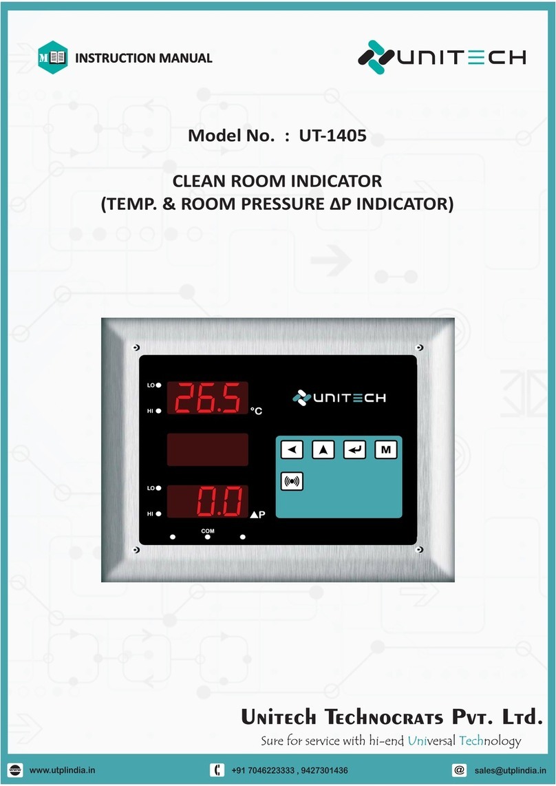
Unitech UT-1405 User manual

@
+91 7046223333 , 9427301436
www.utplindia.in
www
Model No. : UT-1405
TEMP. AND DIFF. PRESS. INDICATOR
[CLEAN ROOM INDICATOR]
INSTRUCTION MANUAL
M
UT-1405UT-1405
888.85.02
888803

@
+91 7046223333 , 9427301436
www.utplindia.in
www
UT-1405
TEMP. AND DIFF. PRESS. INDICATOR
I
WARNING
Electrical Consideration / Precautions
The controller is considered “rack and panel mounted equipment” per EN 61010-1, Safety Requirements for
electrical equipment for Measurement, Control and Laboratory Use, Part 1: General Requirements. Conformity
with 2/23/EEC Low Voltage Directive, requires the user to provide adequate protection against a shock hazard.
The user shall install this controller in an enclosure that prevents OPERATOR access to the rear terminals.
FAILURE TO COMPLY WITH THESE INSTRUCTIONS COULD RESULT IN DEATH OR SERIOUS INJURY.
Shielded twisted pair cable is required for all Analog Input & Output, Process Variables,
RTD, Thermocouple, DC volts-mV, low level signal, mA, Alarm Outputs, and Computer
communication interface circuits.
CAUTION
FAILURE TO COMPLY WITH THESE INSTRUCTIONS MAY RESULT IN PRODUCT DAMAGE.
Power Supply / Wiring Requirements
Applying 240V AC to a controller rated for 12-24VDC will severely damage the controller
and is a fire and smoke hazard.
This controller is suitable for connection to 12 / 24 VDC, power mains.
It is the user responsibility to provide the following
12 / 24 VDC – a switch, fuse (1A, 125A) or a circuit breaker.
The above items should be installed together with UT-1405 for the products electrical protection.
The switch, Fuse or circuit-breaker should be located close to the controller, within easy reach
operator. The switch or Circuit-breaker should be marked as the disconnecting device for the
controller. applying power to Multiple instruments, make sure that sufficient current is supplied,
Otherwise, the instruments may not start up normally due to the voltage drop caused by the in-
rush current.
FAILURE TO COMPLY WITH THESE INSTRUCTIONS MAY RESULT IN PRODUCT DAMAGE.
Disposal action of Instruments follows as per country and regional law and rules & regulation also same in
international. Company might be follows as per rules.
DISPOSAL ACTION
PRE CAUTIONS, WARNING AND DISPOSAL ACTION
Line voltage Wiring

@
+91 7046223333 , 9427301436
www.utplindia.in
www
1
CONTENTS
2. NSTALLATIONI
2.1 EXTERNAL DIMENSION
2.2 MOUNTING
2.3 TECHNICAL SPECIFICATIONS
2.5 WIRING DIAGRAM
3. PROGRAMMING
3.1 OPERATION INTERFACE
3.2 MODE ACCESS FLOW CHART
4.1 CONFIGURATION MODE
4. OPERATIONAL MODES
4.2 SETUP MODE
4.3 CALIBRATION MODE
4.4 CHANGE PASSWORD MODE
4.5 BUZZER MODE.
5. COMMUNICATION [MODBUS RTU] PROTOCOL
5.1 INTRODUCTION
5.2 MODBUS CONFIGURATION BASIC SETTINGS
5.3 REGISTER ADDRESSES FOR MODBUS / RTU PROTOCOL
1. OVERVIEW
1.1 INTRODUCTION
2
2
2
2
3
4
5
6
6
7
8
8
12
13
14
14
15
15
15
15
15
5.4 MODBUS SYSTEM SCHEMATIC.
...................................................................................................
........... ..............................................................................
...................................................................................................
...................................................................................
..............................................................................................................
...................................................................................................
...................................................................................................
...........................................................................................
.............................................................................
....................................................................
...................................................................................
...........................................................................
............................................................................................
.................................................................................
.....................................................................
...........................................................................................
...............................................
.........................................................................................
.............................................
. ..................................
....... ..............................................................
2.4 TECHNICAL FEATURES 5
..........................................................................................
UT-1405
TEMP. AND DIFF. PRESS. INDICATOR

@
+91 7046223333 , 9427301436
www.utplindia.in
www
UT-1405
TEMP. AND DIFF. PRESS. INDICATOR
2
1. Introduction1
Function
Mount Anywhere
Various different configuration levels provide easy access to parameters. There are 4 digit security code
perverts unauthorized changes. Parameters can also be hidden to user to prevent improper configuration
of the unit. There are 4 keys provided for easy configuration and setup.
The UT-1405 product group is Clean Room instruments that must be Flush or Wall mounted. The wiring
terminals must be provided. the UT-1405 is environmentally hardened and, if suitably handled, can be
mounted virtually anywhere in clean room or enclosure wall mounted or Flameproof enclosure or even on
the AHU or Technical Area.
Easy to Configure
1. OVERVIEW
2.1 Dimensions
2. INSTALLATION
Indicator Frame
NOTE : All Dimensions are in mm
The UNITECH's “Clean Room Indicator(T+DP) [UT-1405]” has been specially developed keeping process
measurement requirements of Clean rooms parameters like Temperature & DIFF. PRESS. in Pharmaceutical
industries. The Process Monitor can measure these parameters through inbuilt sensors. The Monitor has
LEDs for Alarms. Temp. and DP will display individually and data transfers to any master device on Modbus
RS-485 communication. It also has communication diagnosis LED. The monitor has inbuilt buzzer for audible
Alarm. It has keypad to programming the instrument by end user. It has Stainless steel Modular Face plate,
which is designed as a mounting accessory for monitor suited for Modular wall Clean Room applications
where you need flush mounting mechanism. This instrument enables you to measure parameters.
UT-1405
888.8
888.85.
5.05
02
100
145
2.4189
18
125
125
90
110
75
136
110
155
30
155
115
90
110
Front ViewSide View Front ViewSide View

@
+91 7046223333 , 9427301436
www.utplindia.in
www
UT-1405
TEMP. AND DIFF. PRESS. INDICATOR
3
2. Mount the frame in the Surface cutout.
1. Cutout required in the back wall or partition : 125[H] X 100[W]
3. Fix the frame on surface by screws.
4. Insert the Power & Communication Cables.
100
125
100
145
155
110
100
145
155
110
Wall OR Partition
surface
FRAME
Indicator
3. Mount the Indication in the Frame.
4. Terminate the Supply and Comm. wires to Indicator.
7. Fix the Indicator on Frame by screws.
2.2 Mounting
Cut Out

@
+91 7046223333 , 9427301436
www.utplindia.in
www
UT-1405
TEMP. AND DIFF. PRESS. INDICATOR
4
2.3 Technical Specifications
Accuracy and
Response Time
Temperature :
DIFF. PRESS. :
0 to 60 °C
-10 to 10 mmWC / -25 to 25 mmWC / -200 to 200 mmWC
Temperature :
Press. Diff. :
0.1 °C
In mmWC : 0.1mmWC / PASCAL : 1 Pa / Hpa : 0.01Hpa
+ 0.25 % on FS Response time : 8 sec
1.0 % on FS Response time : 4 sec+
DIFF. PRESS.
Temperature
4 Digit Seven segment 0.56” Red display
4 Digit Seven segment 0.56” Red display
Input No. of Input 2 Nos. Temperature and DIFF. PRESS.
Display Resolution
“ ” or “ ” indication on displayOPEN OVER
Sensor Break Info.
TECHNICAL SPECIFICATIONS
Indication
Status indication
Alarm modes
Each Channel has 2 LEDs for High [HI] & Low [LO] Alarm status and
Single LED for active Communication. It has also Buzzer for audioable Alarm
Audio Alarm In-built Buzzer for Audio Alarm
Output
Very Low / Low / High / very High (Selectable) in each channel.
High scale / Low scale Full range as per input selection
General
Specificaion
Power Supply 24VDC
Power Consumption 4 Watts Maximum
Prog. parameters
Modbus RTU RS- 485 Isolated Communication
Baud rate, Parity, Node address, Stop bit
Protocols & method
Max Slave Connections
Communication Up to 256 Units
Programmable
Parameters
Alarm Logic
Prog. of Para.
Full Scale high OR Full Scale low
Programming of parameters are done through 4 front keys.
MOC Full SS316 plate and Box, Back Side Wall Mounting MS Cover Frame
Ch-1 [Temperature] :
Ch-2 [DIFF. PRESS.] :
Display [PV]
Display Range
Standard Ranges are :
Range
Other Output Transmitter Power Supply : 24VDC@30mA ,Max. Isolated [If Required]
Read / Write Para. Read : Write :Process value, Decimal point. High - Low set point
Set Point Full range as per input selection
Operating Ambient Temp. : 0~50˚C, DIFF. PRESS. : Below 90% Non condensing
Cable Entry 5 X ” ET⁄
Display Glass Clear glass thougnet type A as per IS 2206
Degree Protection IP 65 as per IS 2147
Enclose Certification
Gas Group
Enclosure is certified by C.M.R.I.
I IIA IIB as per IS 2148/1981
MOC Aluminium Alloy
FlameProof
Temp + DP Input Integral Remote [External]OR

@
+91 7046223333 , 9427301436
www.utplindia.in
www
UT-1405
TEMP. AND DIFF. PRESS. INDICATOR
5
2.4 Technical Features
ØFDA 21 CFR part 11 - GAMP-4 compatible.
Micro controller-based indicator with inbuilt DP measurement.
Ø
Incorporates highly stable built-in sensor.Ø
3 Digit, 0.56" Bright LED display for displaying parameter.Ø
Process parameter Hi and Low LEDs. Status indication for one channel.Ø
User selectable set limits for process value violation.Ø
Inbuilt buzzer to audible process value violation.Ø
Password protection for calibration and programming mode.Ø
Software Calibration for both channels.Ø
MODBUS RTU multi drop RS-485 serial communication for PLC, SCADA, etc.Ø
Programmable devise address, baud rate, (max no. of device is 1-256).Ø
Remote programmable from master device.Ø
Compact, All Stainless Steel enclose with 35 mm depth for installation in prefab panels.Ø
Brick and modular wall mounting and flush mounting.Ø
User programmable offset correction.Ø
Ex. Flameproof model available for Hazardous applications.Ø
.ØThis instrument enables you to measure parameters in the following fields:
HVAC System (Heating, ventilation, Air conditioning, cooling)
Pharmaceutical industry.
Blood Storage stations, pharmacies.
2.5 Wiring Diagram
CAUTION
LINE VOLTAGE
This product is suitable for Supply connection 24 VDC main power supply. It is user
responsibility to provide proper protection for the products electrical protection .
when applying power to various instruments, make sure sufficient current is supplied.
otherwise the instruments may not start up due to the Voltage drop.
AILURE TO COMPLY WITH THESE INSTRUCTION MAY RESULTF
IN INSTRUMENT DAMAGE
CAUTION
WIRING CONSIDERATION
Shielded twisted pair wire is used for all analog I/P, Process sensors RTD,
Thermo-couple, mV-mA DC, Volt DC, Linear input and Communication.
AILURE TO COMPLY WITH THESE INSTRUCTION MAY RESULTF
IN INSTRUMENT DAMAGE
SUPPLY
24 VDC
DC SUPPLY
12
COMMUNICATION
RS-485
34
COMMNICATION
D+D-
INPUT SENSOR
TEMP SENSOR
5678
YELLOW
BLACK
GREEN
RED
UT-1405
1 2 3 4
RS - 485
D- D+
24VDC
24V
SUPPLY
0V
TEMP+DP INDICATOR
COMM.
DP
HL
5 6 7 8
GBYR
TEMP SENSOR
INPUT

@
+91 7046223333 , 9427301436
www.utplindia.in
www
UT-1405
TEMP. AND DIFF. PRESS. INDICATOR
6
3. PROGRAMMING
3.1 Operation Interface
FRONT VIEW
Present Value Displays 4 Digit 7 segment dedicated to display the present value of particular
Channel. In Programing mode it shows Parameter and its values.
Low (LO) LED It indicates the status of Low alarm, LED is activated when value crosse Low
alarm selected value.
COM LED It indicates the active Communication between devices. When LED is Blink,
the communication of device is active.
KEYS
MODE KEY MODE or Function key allows to access the programming Mode groups or
parameters. Press this key to Exit one step in Programming Mode
NORMAL VIEWS
ENTER KEY ENTER Key allows enter into the Parameter, moving from one parameter
to another and accept saving a new value of parameter or a status of
parameter.
UP KEY UP Key allows increasing the value of a selected value digit. It is also used to
UP the parameter in programming mode.
PASS KEY PASS Key allows pass the digit of a value from right to left of a selected
parameter and for EXIT from programming mode. This key is also used for
Acknowledgment of audio buzzer in Normal Mode.
BUZZER ACK.
INCREMENT
PASS Key
UP Key
MODE Key
ENTER Key
COM LED
CH-1 Low Alarm LED
CH-1 High Alarm LED
CH-2 Low Alarm LED
CH-2 High Alarm LED
www.utplindia.in
[ 2 Nos.]
[ 2 Nos.]
[ 2 Nos.]
High (HI) LED It indicates the status of High alarm, LED is activated when value crosse High
alarm selected value.
Display-1 TEMP.
Display-2 DP
UT-1405
888.8
888.85.
5.05
02

@
+91 7046223333 , 9427301436
www.utplindia.in
www
UT-1405
TEMP. AND DIFF. PRESS. INDICATOR
7
PV
SV
3.2 Mode Access Flow Chart.
8888
8888
Normal Mode
Mode Selection
Configuration Setup
Mode Mode
Change
Password Mode
Calibration
Mode
Password Protected
COnf
0000
MODE
aLTY
MODE
ALST
MODE
ALDE
MODE
DeC1
MODE
T1ME
MODE
COMM
MODE
DAMP
SETP
0000
CAL
0000
PASC
0000
Press key to enter into the
Programming mode from
Normal mode
MODE MODE MODE MODE
pass pass pass pass
MODE
1PTY
* PASS CODES
: Default -> 1357.oCOnF
: Default -> 1111.oSEtP
: Default -> 1234.oCAL
: Default -> 1234.oPASC
: Default -> 1234.ob ZZ
1SP1
****
1SP2
****
1SP3
****
1SP4
****
2SP1
****
2SP2
****
2SP3
****
2SP4
****
Password Protected
CAL
CAL1
CAL
RANG
WARNING
INJURY
Programming parameter should be accessed only by Personnel who are
technically competent to do so. Local regulations regarding electrical &
safety must be observed.
FAILURE TO COMPLY WITH THESE INSTRUCTION COULD BE RESULT IN SERIOUS INJURY OR DEATH
Password Protected
1357
CONF
1111
setp
1234
CAL1
1234
b ZZ
1234
PASC
Password Protected
Password Protected
B ZZ
0000
MODE
pass
B ZZ
EN
FREQ
0025
Buzzer
Mode
There will be auto exit to Normal mode facility if no
key is pressed within 1 min.
Press key to Exit from Programming Mode to
Normal mode .
*
*
*
*
These are the whole parameter list. Parameters
can be very as per Type Requirement by User.or
Press key to exit a level in Programming Mode.
NOTE :
MODE
nOnG

@
+91 7046223333 , 9427301436
www.utplindia.in
www
UT-1405
TEMP. AND DIFF. PRESS. INDICATOR
8
ON
OFF PV
Low-Low & Low
NORMAL
VALUE
LOLL
ON
OFF PV
High & High-High
NORMAL
VALUE
High HH
Values are : - Low Low, - Low, - High, - High High.LL Lo H1GH HH
‘Configuration Mode’ will shown by pressing key in the Normal Mode.
4.1 Configuration Mode
4. OPERATIONAL MODES
Scroll the digit by key, Increase by key.
1. : CONFIGURATION MODE PASSWORDPASS
Password for Mode ParametersConf
Default Password for access Config. mode : 1357
2. : ALARM TYPEaLTY
Alarm type of particular Input.
Press key to access sub parameters, the alarm type are as follows :
I. : Input 1 [TEMP.] Alarm 1 Type.1sp1
Default type should be : Lo
Values are : - Low Low, - Low, - High, - High High.LL LO H1GH HH
II. : Input 1 [TEMP.] Alarm 2 Type.
1sp2
Values are : - Low Low, - Low, - High, - High High.LL LO H1GH HH
III. : Input 1 [TEMP.] Alarm 3 Type.
1sp3
Values are : - Low Low, - Low, - High, - High High.LL LO H1GH HH
IV. : Input 1 [TEMP.] Alarm 4 Type.
1sp4
Values are : - Low Low, - Low, - High, - High High.LL Lo H1GH HH
Values are : - Low Low, - Low, - High, - High High.LL LO H1GH HH
VI. : Input 2 [DP] Alarm 2 Type.
2sp2
Values are : - Low Low, - Low, - High, - High High.LL LO H1GH HH
VII. : Input 2 [DP] Alarm 3 Type.
2sp3
Values are : - Low Low, - Low, - High, - High High.LL LO H1GH HH
VIII. : Input 2 [DP] Alarm 4 Type.
2sp4
V. : Input 2 [DP] Alarm 1 Type.2sp1
Default type should be : H1GH
Default type should be : LL
Default type should be : HH
Default type should be : Lo
Default type should be : H1GH
Default type should be : LL
Default type should be : HH

@
+91 7046223333 , 9427301436
www.utplindia.in
www
UT-1405
TEMP. AND DIFF. PRESS. INDICATOR
9
Values are between to Seconds.0000 9999
I. : Input 1 [TEMP.] Alarm 1 Delay Time.
1sp1
Values are between to Seconds.0000 9999
II. : Input 1 [TEMP.] Alarm 2 Delay Time.
1sp2
Values are between to Seconds.0000 9999
III. : Input 1 [TEMP.] Alarm 3 Delay Time.
1sp3
Values are between to Seconds.0000 9999
IV. : Input 1 [TEMP.] Alarm 4 Delay Time.
1sp4
Values are between to Seconds.0000 9999
V. : Input 2 [DP] Alarm 1 Delay Time.
2sp1
Values are between to Seconds.0000 9999
VI. : Input 2 [DP] Alarm 2 Delay Time.
2sp2
Values are : - Enable, - DisableEn D1s
II. : Input 1 [TEMP.] Alarm 2.
1sp2
3. : ALARM STATUS ENABLE/DISABLEaLST
Enable OR Disable Alarm of particular Input.
Press key to access sub parameters, the sub parameters are :
I. : Input 1 [TEMP.] Alarm 1.1sp1
Values are : - Enable, - DisableEn D1s
Values are : - Enable, - DisableEn D1s
Values are : - Enable, - DisableEn D1s
IV. : Input 1 [TEMP.] Alarm 4.
1sp4
III. : Input 1 [TEMP.] Alarm 3.1sp3
Values are : - Enable, - DisableEn D1s
Values are : - Enable, - DisableEn D1s
Values are : - Enable, - DisableEn D1s
VIII. : Input 2 [DP] Alarm 4.
2sp4
VII. : Input 2 [DP] Alarm 3.2sp3
Values are : - Enable, - DisableEn D1s
VI. : Input 2 [DP] Alarm 2.
2sp2
V. : Input 2 [DP] Alarm 1.2sp1
4. : ALARM DELAY IN SECONDSaLde
Delay Time for Alarm Activation of particular Input in Seconds.
Press key to access sub parameters, the sub parameters are :
VIII. : Input 2 [DP] Alarm 4.2sp4
VII. : Input 2 [DP] Alarm 3.2sp3
Values are between to Seconds.0000 9999
Values are between to Seconds.0000 9999

@
+91 7046223333 , 9427301436
www.utplindia.in
www
UT-1405
TEMP. AND DIFF. PRESS. INDICATOR
10
I. : Second.SEC
II. : Minute.M1n
8. : TIME AND DATE SETTINGT1Me
Real Time Date and Clock setting.
Press key to access sub parameters, the sub parameters are :
Real time Second.
Values are between to .0000 0059
Values are between to .0000 0059
Real time Minutes.
I. : Node Address.NoDE
Baud rate for active communication.
II. : Baud Rate.
baud
Parity check for active communication.
III. : Parity.
parI
Stop bit setting for communication.
IV. : Stop Bit.
stOp
5. : COMMUNICATION PARAMETERCOMM
Device Active Master-Slave Communication configuration parameter.
Press key to access sub parameters, the sub parameters are :
Device Address for Communication
6. : INPUT DAMPING.daMp
Damping parameter for input Present value.
Press key to access sub parameters, the sub parameters are :
I. : Input 1 [TEMP.] Damping.11p
Damping for input-1[TEMP.]
II. : Input 2 [DP] Damping.21p
Damping for input-2[DP]
7. : DECIMAL POINT.deC1
Decimal Point for input Present value reading.
Press key to access sub parameters, the sub parameters are :
I. : Input 1 [TEMP.] Decimal Point.11p
Damping for input-1[TEMP.]
II. : Input 2 [DP] Decimal Point.21p
Damping for input-2[DP]
Values are between to .0000 9999
Values are : , , , ,4800 9600 1920 2880 1152
Values are : - None, - Even, - Odd012
Default Value : , don’t Change.1

@
+91 7046223333 , 9427301436
www.utplindia.in
www
UT-1405
TEMP. AND DIFF. PRESS. INDICATOR
11
9. : INPUT CHANNEL ENABLE / DISABLE.1PTY
Set to display the Input channel show or not show.
Press key to access sub parameters, the sub parameters are :
I. : Input 1 [TEMP.] Display.11p
Show Display of input-1[TEMP.]
II. : Input 2 [DP] Display.21p
7. : NO NEGATIVE VALUE.NONG
No negative value for Present input reading. Only zero and positive PV
Press key to access sub parameters, the sub parameters are :
III. : Hours[24Hr.].hour
Values are between to .0000 0024
Real time Hours.
Present Calender Date.
IV. : Day / Date.day
Values are between to .0000 0031
Present Month.
IV. : Month.MOn
Values are between to .0000 0024
Present Year.
V. : Year.year
Values are between to .0000 9999
Enable OR disable Real time setting.
VI. : Real Time Clock Setting.RTCS
Values are between to .0000 9999
Values are : - Enable, - DisableEn D1S
Values are : - Enable, - DisableEn D1S
Show Display of input-2[DP]
I. : Input 1 [TEMP.] Display.11p
Show Positive Display of input-1[TEMP.]
II. : Input 2 [DP] Display.21p
Values are : - Enable, - DisableEn D1S
Values are : - Enable, - DisableEn D1S
Show Positive Display of input-2[DP]

@
+91 7046223333 , 9427301436
www.utplindia.in
www
UT-1405
TEMP. AND DIFF. PRESS. INDICATOR
12
4.2 Setup Mode
‘Setup Mode’ Mode will shown by pressing key, after Mode display.Conf
Scroll the digit by key, Increase by key.
1. : SETUP MODE PASSWORDPASS
Password for Mode ParametersSETP
Default Password for access Setup mode : 1111
ASSIGN SET POINTS FOR EACH INPUT ALARMS
Set the alarm Set Point for Audio [Buzzer] front LED.
Alarm action is as per Configuration Mode Alarm Type [ ]ALTP
Set point for Input-1[TEMP.] Alarm-1
II. : Input 1 [TEMP.] Alarm 2 Set Point.
1sp2
III. : Input 1 [TEMP.] Alarm 3 Set Point.1sp3
IV. : Input 1 [TEMP.] Alarm 4 Set Point.1sp4
VI. : Input 2 [DP] Alarm 2 Set Point.2sp2
VII. : Input 2 [DP] Alarm 3 Set Point.2sp3
VIII. : Input 2 [DP] Alarm 4 Set Point.2sp4
V. : Input 2 [DP] Alarm 1 Set Point.2sp1
2. : Input 1 [TEMP.] Alarm 1 Set Point.1sp1
Set any value between Input-1 Low value to high value.
Set any value between Input-1 Low value to high value.
Set point for Input-1[TEMP.] Alarm-2
Set any value between Input-1 Low value to high value.
Set point for Input-1[TEMP.] Alarm-3
Set any value between Input-1 Low value to high value.
Set point for Input-1[TEMP.] Alarm-4
Set any value between Input-2 Low value to high value.
Set point for Input-2[DP] Alarm-3
Set any value between Input-2 Low value to high value.
Set point for Input-2[DP] Alarm-4
Set point for Input-2[DP] Alarm-1
Set any value between Input-2 Low value to high value.
Set any value between Input-2 Low value to high value.
Set point for Input-2[DP] Alarm-2

@
+91 7046223333 , 9427301436
www.utplindia.in
www
UT-1405
TEMP. AND DIFF. PRESS. INDICATOR
13
I. : Input 1 [TEMP.] Low Calibration.1p12
Apply to Low / Zero signal to Input 1 [TEMP.] and press key.
Calibration of Individual input(Only applicable to External analog input)
2. : CALIBRATION OF INPUT.
CAL1
4.3 Calibration Mode
‘Calibration Mode’ Mode will shown by pressing key, after Mode display.SETP
Scroll the digit by key, Increase by key.
1. : CALIBRATION MODE PASSWORDPASS
Password for Mode ParametersCAL
Default Password for access Setup mode : 1234
II. : Input 1 [TEMP.] High Calibration.1p1s
Apply to High / Span signal to Input 1 [TEMP.] and press key.
IV. : Input 2 [DP] High Calibration.1p2s
Apply to High / Span signal to Input 2 [DP] and press key.
III. : Input 2 [DP] Low Calibration.
1p22
Apply to Low / Zero signal to Input 2 [DP] and press key.
II. : Input 1 [TEMP.] High Calibration.
r1s
IV. : Input 2 [DP] High Calibration.r2s
III. : Input 2 [DP] Low Calibration.r22
I. : Input 1 [TEMP.] Low Range.r12
Set Low / Zero Display Range to Input 1 [TEMP.]
Display range Of Individual input(Only applicable to External analog input)
2. : DISPLAY RANGE OF INPUT.
rEnG
Set High / Span Display Range to Input 1 [TEMP.]
Set Low / Zero Display Range to Input 2 [DP]
Set High / Span Display Range to Input 2 [DP]

@
+91 7046223333 , 9427301436
www.utplindia.in
www
UT-1405
TEMP. AND DIFF. PRESS. INDICATOR
14
Set the new Password for Configuration [ ] ModeCONF
2. : CONFIGURATION MODE PASSWORD.
Conf
Scroll the digit by key, Increase by key.
1. : CHANGE PASSWORD MODE PASSWORDPASS
Password for Mode ParameterspAsC
Default Password for access Setup mode : 1234
‘Change Password Mode’ Mode will shown by pressing key, after Mode display.CAL
4.4 Change Password Mode
Configuration Mode default password : 1357
Setup Mode default password : 1111
Set the new Password for Setup [ ] Modesetp
3. : SETUP MODE PASSWORD.
Setp
Calibration Mode default password : 1234
Set the new Password for Calibration [ ] ModeCAL1
4. : CALIBRATION MODE PASSWORD.
CAL1
Buzzer Mode default password : 1234
Set the new Password for Buzzer [ ] ModeB ZZ
5. : BUZZER MODE PASSWORD.
B ZZ
Change Password Mode default password : 1234
Set the new Password for Change Password [ ] ModepASC
6. : CHANGE PASSWORD MODE PASSWORD.
pASC
‘Buzzer Mode’ Mode will shown by pressing key, after Mode display.CAps
4.5 Buzzer Mode
Set this parameter to Enable OR Disable the audible buzzer alarm
2. : ENABLE OR DISABLE BUZZER.
B ZZ
Scroll the digit by key, Increase by key.
1. : CALIBRATION MODE PASSWORDPASS
Password for Mode ParametersB ZZ
Default Password for access Setup mode : 1234
Values are : - Enable, - DisableEn D1s
Default value is : 0025
Set the On-off Frequency of Buzzer.
3. : SET BUZZER FREQUENCY.
FREQ
CAUTION
PASSWORD PRECAUTIONS
FAILURE TO COMPLY WITH THESE INSTRUCTION MAY RESULT IN INSTRUMENT DAMAGE
*
*
After Changing old password, all parameter are locked. All Modes are not
accessible without new password.
Changed password should be remembered , it cannot be Reset at site.

@
+91 7046223333 , 9427301436
www.utplindia.in
www
UT-1405
TEMP. AND DIFF. PRESS. INDICATOR
15
5. COMMUNICATION [MODBUS RTU] PROTOCOL
5.1 Introduction
The unit can be connected in MODBUS/RTU communication data link protocol to messaging
structure, widely used to establish master - slave communications between devices. Each
device must have unique No. node address. Before starting any communication, choose a
baud rate compatible to the host device. A Modbus data sent from a master to slave tells the
selected slave what to do and what information to send back.
5.2 MODBUS Configuration Basic settings
The Basic settings for RS-485 Modbus protocol are as follows :
Band rate
Start bit
Data bit
Stop bit
Parity
9600
1
8
1
none
5.3 Register addresses for MODBUS / RTU Protocol
The addressees for RS-485 Modbus protocol are as follows :
5.4 MODBUS system schematic.
DATA+
The system schematic for RS-485 Modbus protocol are as follows :
DATA-
Ethernet
RS-232
or
RS-485
CONVERTER
D- D+
34
UT-1405 Device-1
D- D+
34
D- D+
34
D- D+
34
RS-485 BUS
ADD:1 ADD:2 ADD:3 ADD:N
RS-485 BUS
Upto 256
devices
UT-1405 Device-2 UT-1405 Device-3 UT-1405 Device-256
2 core 1 sq/mm shielded cable
COMPUTER- SCADA
TEMP ALARM-2 SET POINT
TEMP ALARM-3 SET POINT
TEMP ALARM-4 SET POINT
40007
40009
40008
40010
40011
40012
40013
40014
READ / WRITE
READ / WRITE
READ / WRITE
READ / WRITE
READ / WRITE
READ / WRITE
DP ALARM-2 SET POINT
DP ALARM-3 SET POINT
DP ALARM-4 SET POINT
DP ALARM-1 SET POINT
READ ONLY
SR.
1 TEMP PRESENT VALUE [PV]
PARAMETER ABSOLUTE ACCESS
40001
READ / WRITE
3 40003
READ ONLY
2 TEMP DECIMAL POINT 40002
READ / WRITE
4 40004
READ ONLY
5 40005
READ ONLY
6 40006
NO. ADDRESS TYPE
DP PRESENT VALUE [PV]
DP DECIMAL POINT
READ ONLY
READ ONLY
7
9
8
10
11
12
13
14
TEMP ALARM-1 SET POINT
TEMP ALL 4 ALARM STATUS
MINUTES AND SECONDS
DAY AND HOURS
40021
40023
40022
40024
40025
40026
40027
40028
40029
READ / WRITE
READ / WRITE
YEARS AND MONTH
SR.
16
PARAMETER ABSOLUTE ACCESS
40015
18
4001717
40016
19
40018
20
40019
40020
NO. ADDRESS TYPE
21
22
23
25
24
READ / WRITE
READ / WRITE
26
27
29
28
15
DP ALL 4 ALARM STATUS
AHU RUN STATUS [IF APP.]
READ ONLY
READ ONLY
READ ONLY
READ ONLY
READ ONLY
READ ONLY
READ ONLY
WRITE ONLY
WRITE ONLY
WRITE ONLY
WRITE ONLY
MINUTES AND SECONDS
DAY AND HOURS
YEARS AND MONTH
SAVE ABOVE [26~28] DATA
NOTE : Sr. no. 22 is applicable if AHU Status digital signal is available.
N/A
N/A
N/A
N/A
N/A
N/A
N/A

Other manuals for UT-1405
2
Table of contents
Other Unitech Measuring Instrument manuals
Popular Measuring Instrument manuals by other brands

Ista
Ista ultego III eco manual
iET
iET PRS-300 Series Operation manual
Santec
Santec OptoTest OP760 Series instruction manual

Humboldt
Humboldt GeoGauge product manual
Hanna Instruments
Hanna Instruments 96711C instruction manual
Dwyer Instruments
Dwyer Instruments TP2-10 Specifications-installation and operating instructions
BRUEL & KJAER
BRUEL & KJAER B&K 2245 Getting started

Aquametro Oil & Marine
Aquametro Oil & Marine CONTOIL DFM Series Mounting and operating instructions
EXFO
EXFO FTB-5230S user guide
Rotronic
Rotronic CF1 Series Short instruction manual
BEKA
BEKA FOUNDATION BA444NDF-F manual

Biolase
Biolase epic V series user manual

