Unitech UT-1405 User manual

Model No. : UT-1405
Model No. : UT-1405
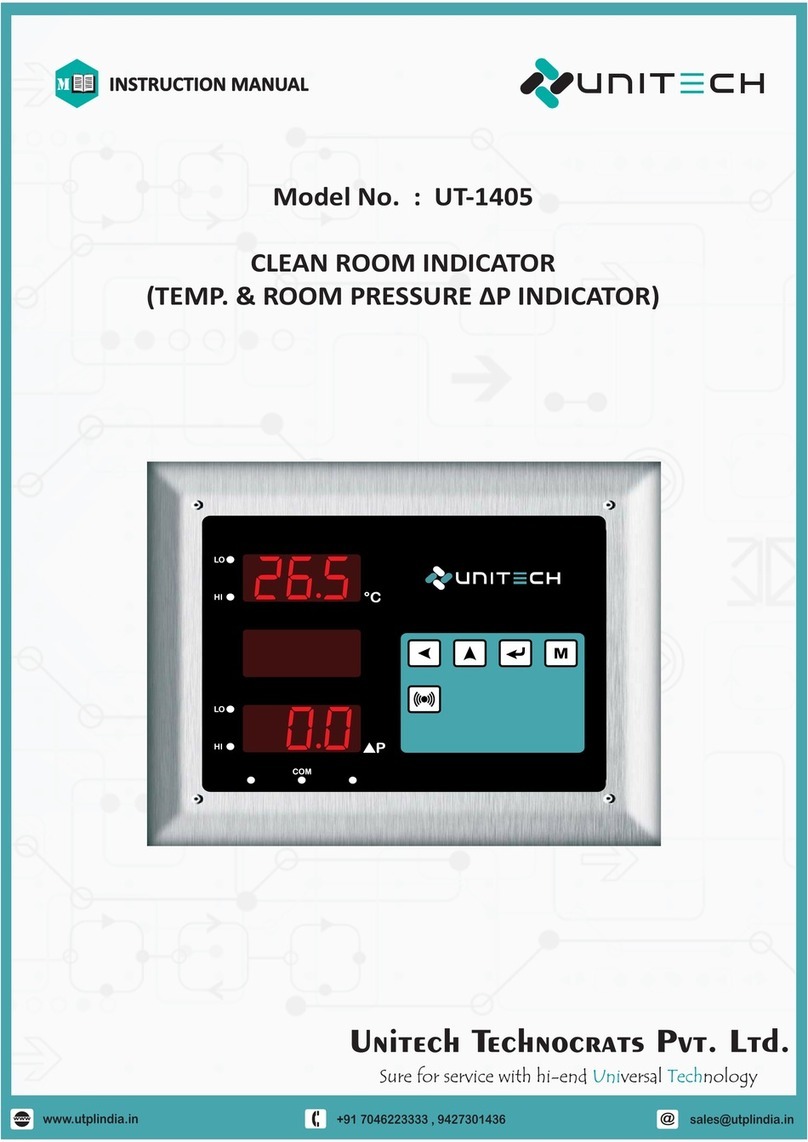
CLEAN ROOM INDICATOR
zOPERATION MANUAL z
(TEMP. & P INDICATOR)Δ
+91 94273 01436
Sales:
www.utplindia.in
Website:
Sure for service with hi-end versal nologyUni TechSure for service with hi-end versal nologyUni Tech
E-mail :
Add.-78/1/Z/3, Makarpura GIDC, Makarpura, Vadodara Ph : +91 7046223333

CLEAN ROOM INDICATOR
Model No. : UT-1405
These instrument accepts inputs from standard Temp. sensor or
internal sensor. The instrument displays the temperature (ºC) in the
range of 0 to 100ºC and press. diff. in 0 to 100 pascal on Three digit
segment Red LEDs.with High and Low alarm led outputs and are
settable using programming modes.
Unitech Instrument’s Clean Room Indicator is designed to display
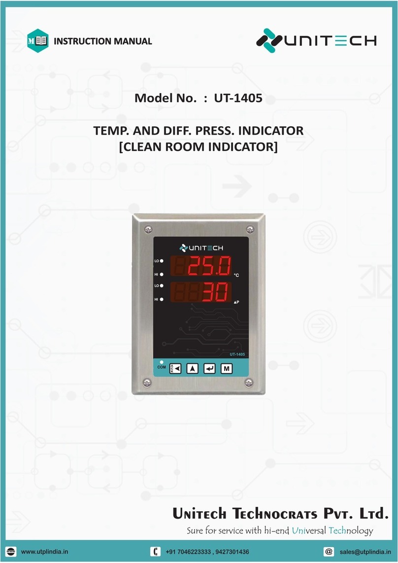
Temperature and Room Pressure Difference in one unit.
INTRODUCTION
zz
CONTENTS
zz
Features:
Micro based design.
Elegant appearance, easy to operate and compact in size.
Highly accurate and sturdy in operation.
T display for simultaneous indication of T .
processor
wo & P
RS-485 Communication available.
Δ
PAGE:1
PROGRAMMING FLOW CHART
TECHNICAL SPECIFICATION
FRONT PANEL DESCRIPTION
INTRODUCTION
TERMINAL ARRANGEMENT
INSTALLATION
5
3
2
4
4
OPERATION 6
ERROR MESSAGE AND TROUBLESHOOTING 9
COMMUNICATION PROTOCOL 9
1
F
F
F
F
F
F
F
F
F
+91 94273 01436
Sales:
www.utplindia.in
Website:
Sure for service with hi-end versal nologyUni TechSure for service with hi-end versal nologyUni Tech
E-mail :
Add.-78/1/Z/3, Makarpura GIDC, Makarpura, Vadodara Ph : +91 7046223333

Model No. : UT-1405 PAGE:2
SR
SR
1
2
4
5
3
6
7
8
NO
9
NO
DISPLAY
888
KEY
Low
COM
Sensor
High
PARTICULAR
FUNCTION(M)
Red LED will blink when there is a Communication.
Internal Temp. Sensor if applicable.
Red LED will glow on low Process values of ºC & PΔ
ENTER
DESCRIPTION
Seven Segment LED displays of Temp and Diff. Press.
DESCRIPTION
Press to access the programmable
Parameter.
(UP)
(PASS)
FRONT PANEL DESCRIPTION
zz
Press to change Temp Set point in Normal
Mode and increase selected digit or value
in Programming Mode.
Acknowledgment of Buzzer ring at Low &
High Values of ΔºC,%Rh, and P
Red LED will glow on high Process values of ºC & PΔ
Press to change Rh Set point in Normal
Mode and to change digit selection or
selected value in Programming Mode.
M
ACK. BUZZER
10
Press to change Set point in Normal
Mode and
dP
to accept modified digit or
value in Programming Mode.
314
Low
High
115
Low
High
ºC
P
M
1
2
3
4
5
6
7
8
9
10
COM
+91 94273 01436
Sales:
www.utplindia.in
Website:
Sure for service with hi-end versal nologyUni TechSure for service with hi-end versal nologyUni Tech
E-mail :
Add.-78/1/Z/3, Makarpura GIDC, Makarpura, Vadodara Ph : +91 7046223333

zTECHNICAL SPECIFICATION z
+91 94273 01436
Sales: Email :
www.unitechinstrument.com
Website:
“Sure for service with hi-end versal nology”Uni Tech
Add.-503/504,Helix Complex , Opp. Surya Hotel, Sayajigunj, Vadodra-05. Gujrat. INDIA, PH-0265 6623551
Model No. : UT-1405 PAGE:3
FDA 21 CFR part 11 - GAMP-4 compatible.
LEDs. S both
Microcontroller based indicator with inbuilt Temperature & DP measurement in single enclosure.
Incorporates highly stable built-in or Remorte Temp. & DP sensor.
3 Digit, 0.56" bright LED display for displaying Temperature and DP
Process parameter Hi and Low tatus indication For channel.
User selectable set limits for process value violation.
Inbuilt buzzer to audible process value violation.
Password protection for calibration and programming mode.
Software Calibration for both channels.
MODBUS RTU multi drop RS-485 serial communication for PLC, SCADA, etc.
Programmable devise address, baud rate, (max no. of device is 1-256).
Remote programmable from master device.
User programmable offset correction.
Compact, All Stainless Steel enclosure with 35 mm depth for installation in prefab panels.
Brick and modular wall mounting and flush mounting.
FDA21 CFR part 11 compliance data logging software available
Ex. Flameproof model available for Hazardous applications.
Technical Specification
Flame
Proof
Material of constructions
Cable entery
Gas group
Enclose certification
Display glass
Degree protection
I IIA IIB as per IS 2148/1981
Enclosure is certifies by C.M.R.I. dhanbad
Clear glass thognet type A as per Is 2206
IP 65 as per IS 2147
5x3/4“ET
Aluminum alloy
Technical data
Nos. of input
Input
Indication
Range
Accuracy
Transmitter power supply
Comunication
Programmable
Parameters
Other
Supply voltage Power consumption
24 v DC @ 4 watts maximum
Operating ambient temperature and humidity
Temperatures input
2 nos .(TEMP + DP)
- 0~50 °C
- Below 90%, non condensing
Mounting
Bricks and modules wall Flush panel mounting.
DP input
Integral Or Remote (external)
Integral Or Remote (external)
24V/5V DC @ 30 mA max, isolated from I/p & O/P.
Temperatures
DP
Channel-1 : 3 digit Seven segments 0.56” RED display.
Channel-2 : 3 digit Seven segments 0.56” RED display.
LEDs for visual alarms, Buzzer for audible alarm, LED for 485-comm.
Temperatures 0 to 60.0 *C with decimal point.
Display Resolution
Temperatures 0.25 % on FS Response time : 8 sec
Status indication
Read /write parameter Read: Procces value ,decimal point. Write: Hi Low set point.
Programmable parameter
Modbus RTU RS- 485 Isolated communications.
Baud rate , Parity , Node address , stop bit.
Communication Protocol
Full range as per input selection.
Programming of parameters Through 4 tactile keys (with password protections)
No. of slave ID Total 1-256 unit.
Alarm logic Full Scale HI OR Full scale Low
MOC Full S S 316 plate and box , back side wall mounting M S covers.
Set point / High scale / Low scale
-10 to 10 mm / -25 to 25mm / -100-100 mm /-200 to 200 mm wc
mm wc : 0.1 / PA : 1 / Hpa :0.01
1 % on FS in all unit Response time : 1 sec
DP
DP

Model No. : UT-1405 PAGE:4
INSTALLATION
zz
zTERMINAL CONNECTION z
COMMUNICATION : RS-485 interface Terminal
POWER SUPPLY : 24VDC Supply Voltage.
Terminal Detail
NOTE : FOR INTERNAL SENSOR TEMP / RH / DP TERMINALS ARE NOT AVAILABLE
TEMP & RH SENSOR : 4 Wire TEMP. + HUMIDITY
SENSOR WITH WIRE CODE.
T + RH SENSOR
YELLOW
BLACK
RED
GREEN
T + RH SENSOR
YELLOW
BLACK
RED
GREEN
+91 94273 01436
Sales:
www.utplindia.in
Website:
Sure for service with hi-end versal nologyUni TechSure for service with hi-end versal nologyUni Tech
E-mail :
Add.-78/1/Z/3, Makarpura GIDC, Makarpura, Vadodara Ph : +91 7046223333

Model No. : UT-1405 PAGE:5
PROGRAMMING FLOW CHART
zz
PasswordSelection
Mode
MOD
seL
-
Configuration
Mode
Change
pas
MOD
-
CH6
000
oLd
pas
---
PAS
new
-
Calibration
Mode
Setup
Mode
oFF
15
prs
08
prs
GEn
no
FCt
SEt
MM
p-u
n1t
dmp
-
03
Prs
GEn
04
tmp
-
01
Add
nod
rAt
bud
96
MOD
Con
F1G
000
Ent
pas
Lo
AL1
tMp
tmp
-
Lo
AL2
Prs
Lo
AL2
Lo
AL1
Prs
non
1tY
PAr
Password Protected
Ct1
445
Ct7
Mxf
518
oFF
tm-
000
oFF
Pr-
000
Mnf
-
MOD
set
000
Ent
pas
200
sp1
tmp
tmp
sp2
Prs
sp2
sp1
Prs
400
020
050
UP
-
-
Password Protected
1br
MOD
-
CAL
000
Ent
pas
---
Lo
Prs
prs
H1
---
Password Protected
Press key
MPress key Press key Press key Press key
+91 94273 01436
Sales:
www.utplindia.in
Website:
Sure for service with hi-end versal nologyUni TechSure for service with hi-end versal nologyUni Tech
E-mail :
Add.-78/1/Z/3, Makarpura GIDC, Makarpura, Vadodara Ph : +91 7046223333

Model No. : UT-1405 PAGE:6
Parameter Description Range Default Value
CONFIGURATION MODE PARAMETER
Password for Parameter Setting
Values between 000
Password for Configuration Parameter
000 to 999
Scroll the digit by key, increase by key
1. CONFIGURATION MODE
non
1tY
PAr
000
Ent
pas
Temperature Alarm-1 type
To Activate Buzzer on this value.
Change the type by key or key.
Lo
AL1
tmp
-
: Active in Low Lo
Lo
: Active in Very Low
vLo
: Active in Very High
vH1
: Active in High
H1
: Disabled
dsb
Temperature Alarm-2 type
To Activate Buzzer on this value.
Lo
AL2
tmp
-
: Active in Low Lo
Lo
: Active in Very Low
vLo
: Active in Very High
vH1
: Active in High
H1
: Disabled
dsb
Pressure Diff. Alarm-1 type
To Activate Buzzer on this value.
Lo
AL1
prs
: Active in Low Lo
Lo
: Active in Very Low
vLo
: Active in Very High
vH1
: Active in High
H1
: Disabled
dsb
Pressure Diff. Alarm-2 type
To Activate Buzzer on this value.
Lo
AL2
prs
: Active in Low Lo
Lo
: Active in Very Low
vLo
: Active in Very High
vH1
: Active in High
H1
: Disabled
dsb
01
Add
nod
Node Address
Node address for Communication.
Scroll the digit by key, increase by key
Values between 01
00 to 99
Baud Rate.
Baud Rate for Communication.
Change the Value by key or key
rAt
bud
96
Change the type by key or key.
Change the type by key or key.
Change the type by key or key.
48
96
192
: Baud rate 4800
: Baud rate 9600
: Baud rate 19200
96
Parity
Parity for Communication.
Change the Value by key or key Evn
odd
non
: Even Parity
: Odd Parity
: None
non
03
PRS
dmp
-
Pressure Damping
Note: Factory set Value
Values between 03
00 to 10
Temperature Gain
Note: Factory set Value
Values between 04
00 to 14
GEn
04
tmp
-
Change the value by key or key.
Change the value by key or key.
+91 94273 01436
Sales:
www.utplindia.in
Website:
Sure for service with hi-end versal nologyUni TechSure for service with hi-end versal nologyUni Tech
E-mail :
Add.-78/1/Z/3, Makarpura GIDC, Makarpura, Vadodara Ph : +91 7046223333

PAGE:7
Description Range Default Value
Pressure Offset Factory set Value
Note: Factory set Value
Values between
Change the value by key or key.
Pressure Gain Factory set Value
Note: Factory set Value
Change the value by key or key.
15
00 to 62
Values between 08
00 to 14
Change the value by key or key. Yes
no
:Yes
:No no
Pressure Diff. Unit Selection
Change the value by key or key. mmw
pa
:mmWC
:PASCAL
Unit for Press. Diff. Display Value
--- mmw
---
2. SETUP MODE
Password for Parameter Setting
Description Range Default Value
Values between 000
Password for Configuration Parameter
000 to 999
Scroll the digit by key, increase by key
SETUP MODE PARAMETER
Temperature Alarm 1 Set point
Values between
Set point for buzzer activation.
000 to 999
Scroll the digit by key, increase by key
Temperature Alarm 2 Set point
Values between
Set point for buzzer activation.
000 to 999
Scroll the digit by key, increase by key
200
400
Pressure Diff Alarm 1 Set point
Values between
Set point for buzzer activation.
000 to 999
Scroll the digit by key, increase by key
Pressure Diff Alarm 2 Set point
Values between
Set point for buzzer activation.
000 to 999
Scroll the digit by key, increase by key
020
050
+91 94273 01436
Sales:
www.utplindia.in
Website:
Sure for service with hi-end versal nologyUni TechSure for service with hi-end versal nologyUni Tech
E-mail :
Add.-78/1/Z/3, Makarpura GIDC, Makarpura, Vadodara Ph : +91 7046223333
Model No. : UT-1405

Model No. : UT-1405 PAGE:8
Parameter Description Range Default Value
Factory set Value
445
Ct1
mnf
-
Factory set Value
518
Ct7
mxf
-
oFF
tm-
000
-
Temperature Offset
Values between
Offset to Temp. value
000 to 999
Scroll the digit by key, increase by key 000
000
pr-
off
-
Pressure Offset
Values between
Offset to Humidity value
000 to 999
Scroll the digit by key, increase by key 000
3. CALIBRATION MODE
PASSWORD PROTECTED
Parameter Description Range Default Value
Password for Parameter Setting
Values between
Password for Configuration Parameter
000 to 999
Scroll the digit by key, increase by key
000
Ent
pas
Pressure Low Calibration
Apply Press. Low signal and press key
---
Lo
Prs
Pressure Low
---
Pressure High Calibration
Apply Press. High signal and press key
---
H1
prs
Pressure High
---
CALIBRATION MODE
+91 94273 01436
Sales:
www.utplindia.in
Website:
Sure for service with hi-end versal nologyUni TechSure for service with hi-end versal nologyUni Tech
E-mail :
Add.-78/1/Z/3, Makarpura GIDC, Makarpura, Vadodara Ph : +91 7046223333

Model No. : UT-1405 PAGE:9
4. CHANGE PASSWORD MODE
Parameter Description Range Default Value
000
Pas
oLd
New Password.
Scroll the digit by key, increase by key. Values between 000 to 999
New Desired Password
Old Password.
000
Scroll the digit by key, increase by key. Values between 000 to 999
Existing Password
As reqd.
---
000
Pas
oLd
Symptom Probable Solution
-Sensor break error
-Sensor not connected
-Replace sensor
-Check the sensor is connected correctly
Keypad no
function
-Keypads are locked
-Keypads defective
-Check Keypad continuity?
All LED’s
and display
not light
-No power to controller
-Control circuit failure
-Check power lines connection
-Check Control Supply Voltages.
-Replace keypads
OPEn
ERROR MESSAGE AND TROUBLESHOOTING
zz
REGISTER ADDRESS FOR MODBUS RTU PROTOCOL
zz
SR NO PARAMETERS ABSOLUTE ADDRESS ACCESS TYPE
1 PRESS 40001 READ ONLY
2 TMP 40002 READ ONLY
3 PRESS SET POINT 1 40003 READ / WRITE
4 PRESS SET POINT 2 40004 READ / WRITE
5 TEM P SET POINT 1 40005 READ / WRITE
6 TEM P SET POINT 2 40006 READ / WRITE
7 PRESS ALARM 1 STATUS 40007 R EAD O NLY
8 PRESS ALARM 2 STATUS 40008 R EAD O NLY
9 TEM P ALARM 1 S TATUS 40009 R EAD ONLY
10 TEMP ALARM 2 STATUS 40010 READ ONLY
+91 94273 01436
Sales:
www.utplindia.in
Website:
Sure for service with hi-end versal nologyUni TechSure for service with hi-end versal nologyUni Tech
E-mail :
Add.-78/1/Z/3, Makarpura GIDC, Makarpura, Vadodara Ph : +91 7046223333

PAGE:10
NOTES :
+91 94273 01436
Sales:
www.utplindia.in
Website:
Sure for service with hi-end versal nologyUni TechSure for service with hi-end versal nologyUni Tech
E-mail :
Add.-78/1/Z/3, Makarpura GIDC, Makarpura, Vadodara Ph : +91 7046223333
Model No. : UT-1405

Other manuals for UT-1405
2
Table of contents
Other Unitech Measuring Instrument manuals
