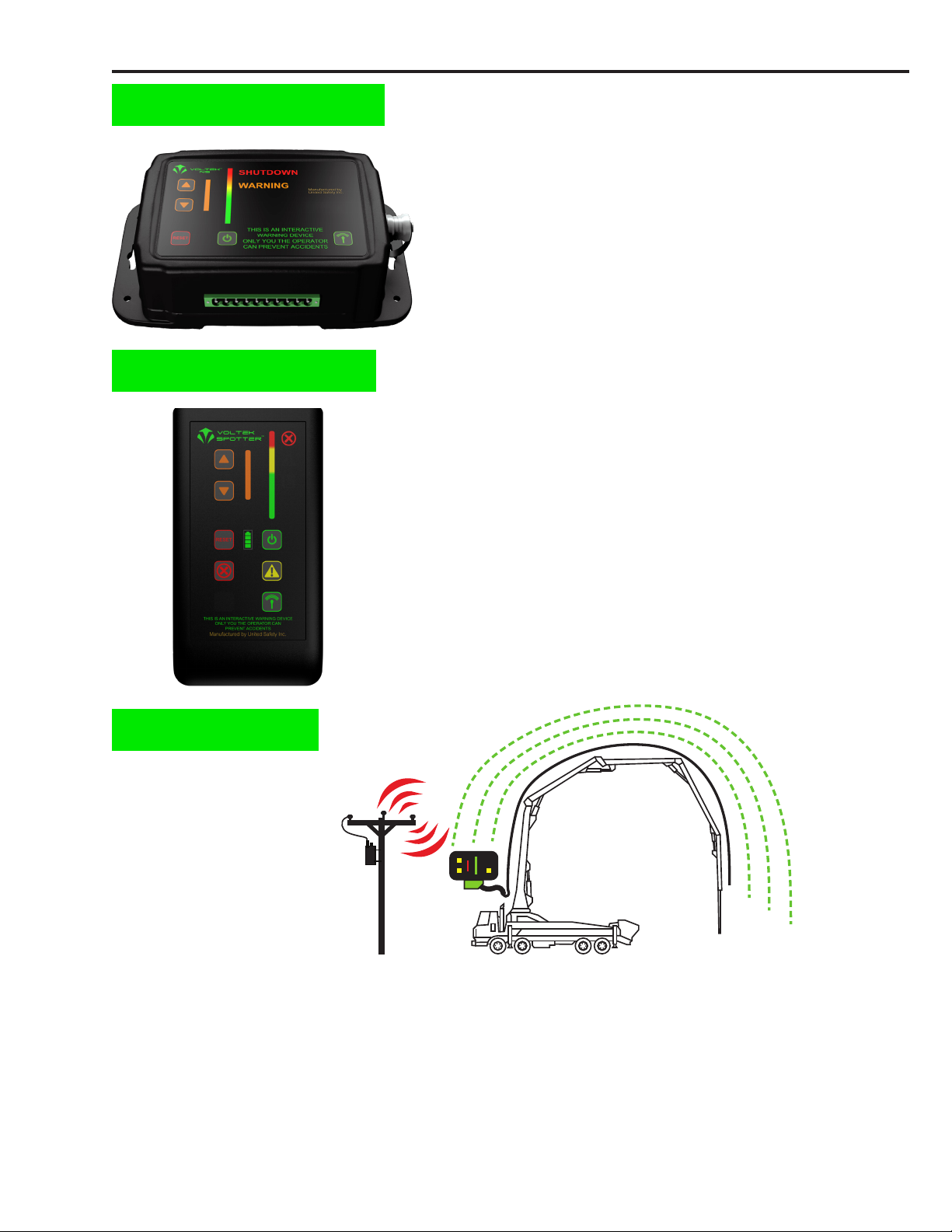
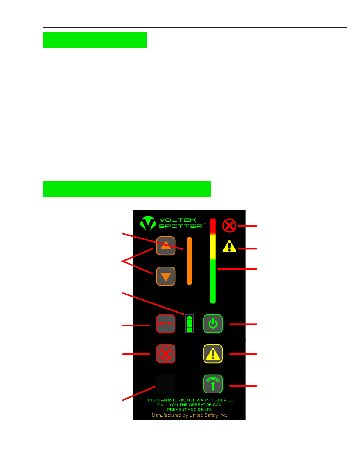
E-Field strength meter:
The antenna of the Voltek NS is sensitive to certain frequencies within the E-eld surrounding overhead
power lines. The NS measures the relative intensity of these frequencies and displays this information on
the color coded E-eld strength meter.
• GREEN – Indicates relatively low E-eld strength: you are within a safe distance of operation.
• YELLOW – Indicates strong E-eld presence: you are operating within close proximity of a power
line–work carefully and remain alert. When the Voltek NS indicates WARNING on the meter, the
external siren will alert you with a pulsating tone with increasing frequency as you move closer to the
power line.
• RED – Indicates very strong E-eld - the Voltek NS will indicate SHUTDOWN and the siren will be in
full alarm with a constant tone (If installed, the E-stop/hydraulic circuits will be interrupted, stopping or
shutting down machine).
Setting the sensitivity level:
Always start with the Voltek with sensitivity set to maximum until you are able to locate nearby power
lines. Once an overhead power line has been identied, adjust sensitivity accordingly. Move equipment
to the closest proximity to the power line while maintaining a safe distance (no closer than 20 feet) and
set the Voltek NS sensitivity to indicate SHUTDOWN, then move equipment away. Now the Voltek NS is
set to your specic job-site and will prevent you from encroaching on your predetermined proximity to the
power line.
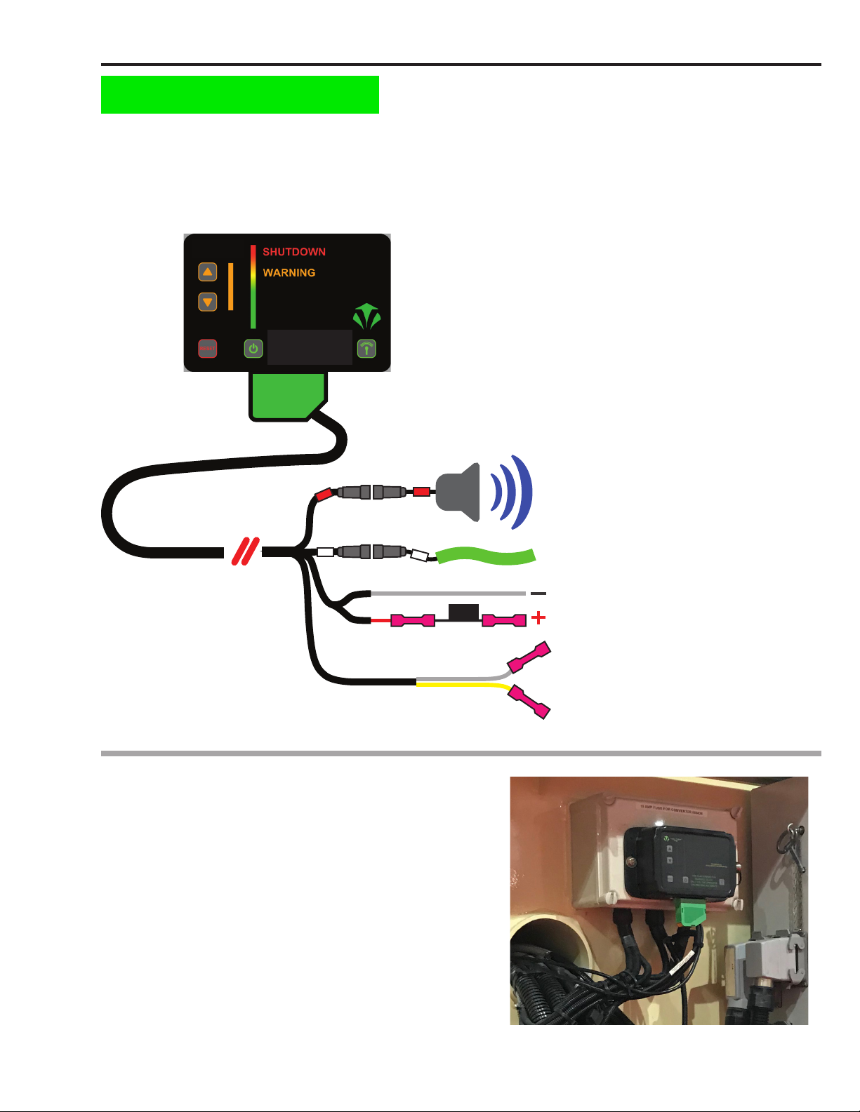
Hydraulic system/E-stop integration:
The Voltek NS has a built in relay circuit which can integrate and control the hydraulic cut out or E-stop
systems on your equipment and stop or shut down your machinery before it contacts a power line. When
the Voltek NS E-eld strength meter is in the red, it will indicate SHUTDOWN and break continuity with
the circuit it is integrated with, which will disable your machine. Once this occurs, hold down the RESET
button and move your equipment away from the E-eld until meter is back in the yellow or green. If
the reset button is released before you are back in the yellow or green, the Voltek NS will go back into
shutdown mode.
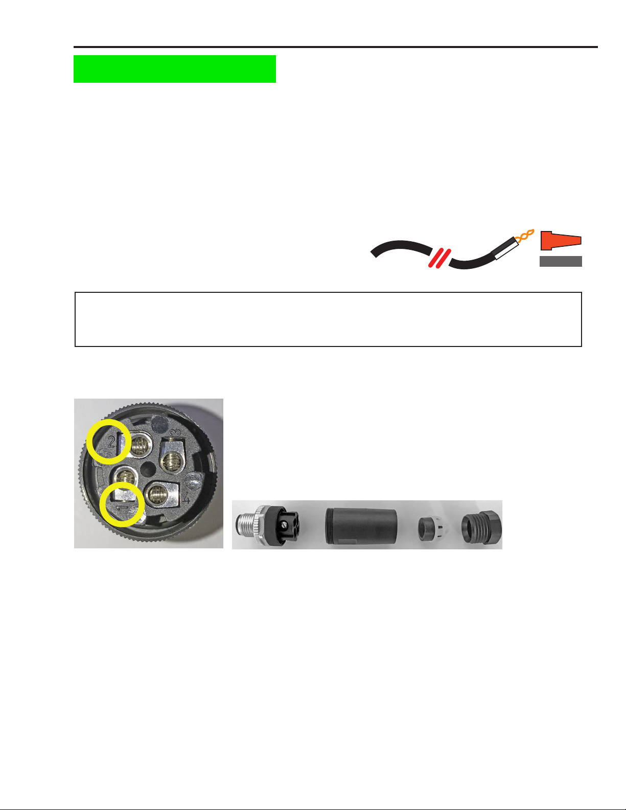
Antenna self check:
The Voltek NS conducts a self check of the antenna every 30 seconds to ensure proper operation and to
detect any faults with the system. The sensitivity meter will briey display a dashed line when the antenna
self check occurs. If a fault is detected, the sensitivity meter will continue to display a dashed line and you
will hear an intermittent tone from the siren. A fault is usually caused by damage to the antenna. If this
occurs, inspect antenna for cuts or other damage and replace if necessary.
Resetting SHUTDOWN alert: (if feature has been integrated with your equipment)
If the SHUTDOWN alert has been activated and the machinery has stopped operating or moving, press
and HOLD the RESET button to allow the operator to move the equipment away from the power line until
the E-eld strength meter is in the yellow “warning” or green level. If the button is not held until the meter
indicates yellow or green the SHUTDOWN mode will still be active.
Turning the Voltek NS off:
Press and hold the power button until the unit turns off (approximately two seconds).
System Overview and operation: (continued)
IMPORTANT NOTE: This feature is optional. For some applications, the sudden
stopping of equipment due to this feature can potentially be hazardous. It is up to
your discretion whether or not you wish to use this feature.
Voltek NS User Guide Page 8