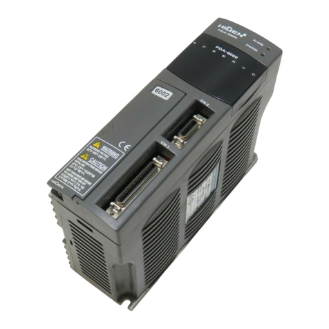
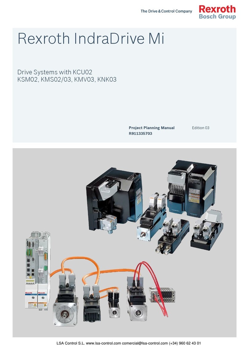
Higen FDA7000 Series User manual

OPERATION MANUAL
AC Servo Drive
FDA7000/FDA7000-H Series
Ver 1.5 (Soft. Ver. 2.40 ~)
FDA7000EX Series
Ver 1.5 (Soft. Ver. 3.29 ~)
FDA7000 Series
Servo Drive User Manual

Essential notes before use
A. Checking Motor ID certainly.
: Enter the motor ID indicated on the motor name plate to the parameter of “P01-01”.
For details on the motor ID, refer to Chapter 3 of this manual.
B. Checking Power of servo drive.
: FDA7001 ~ FDA7150 : AC 220V 50/60[Hz]
: FDA7020-H0 ~ FDA7750-H0 : AC 380V 50/60[Hz]
: FDA7020-H1 ~ FDA7150-H1 : AC 440V 50/60[Hz]
C. Checking Encoder ID certainly.
Encoder
Type
Manual
setting
INC
2000
INC
2500
INC
3000
INC
5000
INC
6000
INC
2048
ABS
11/
13bit
INC
17/
33bit
ABS
17/
33bit
P01-12
[Encoder ID]
Enc-0
Enc-A
Enc-b
Enc-C
Enc-d
Enc-E
Enc-F
Enc-G
Enc-P
Enc-R
When you set the encoder ID to “Enc-0”, you can change the value of P01-13 (Encoder pulse
rate). But if you set the encoder ID to “Enc-A ~ Enc-R”, you cannot change the value of P01-13.
Never connect the encoder cable to COM port.
D. Operate servo system after auto-tuning is off. (P02-17)
: Always cancel the autotuning during normal operation after gain setting using autotuning.
E. Motor handling
: Avoid impacting to the encoder in connecting coupling to the Motor shaft or operating.
F. Recommended specification of Encoder wiring.
Encoder type
Page of wiring explanation
15 line incremental encoder
2-24
9 line incremental encoder
2-25
Absolute encoder 11bit
2-26
Absolute/Incremental encoder 17bit
2-27
G. Separate GND24 (CN1-24, 25) and GND (CN1-1, 8, 26, 33, 34, 36).
: If connected in common, it may cause malfunction and damage of servo drive.
H. Treatment of the servo motor attached holding brake .
: The brake built in the servo motor is a normal closed type brake. Which is used only to hold
and can't be used for braking. Use the holding brake only to hold a stopped servo motor.
I. Do not supply AC at N, P connector when connect the power line to
Small and Medium capacity servo drive.
: If main power is DC power, because N connector (-) voltage and P connector (+) voltage,
burnout of servo drive when N, P connector is supplied AC power.
Choose positively necessary AC and DC power, and use.

Contents
Contents
Chapter 1. Model check and handling
1.1. Model check................................................................................. 1-1
1.1.1. Servo drive model classification .............................................. 1-1
1.1.2. Servo motor model classification............................................. 1-1
1.2. Servo drive specification ............................................................ 1-2
1.2.1. Power specification of AC 220V Series ................................... 1-2
1.2.2. Power specification of AC 380V Series ................................... 1-2
1.2.3. Common specifications. .......................................................... 1-3
1.3. Combination table of servo drive and motor ............................ 1-4
1.3.1. AC220V series servo drive and motor..................................... 1-4
1.3.2. AC380V series servo drive and motor..................................... 1-5
1.3.3. Explosion proof series servo drive and motor ......................... 1-6
1.4. Rated specification of servo motor............................................ 1-7
1.4.1. AC220V series servo motor .................................................... 1-7
1.4.2. AC380V series servo motor .................................................. 1-16
1.4.3. Explosion proof series servo motor ....................................... 1-21
1.5. Installation ................................................................................. 1-24
1.5.1. Installation of servo drive....................................................... 1-24
1.5.2. Servo motor installation......................................................... 1-24
1.6. Handling ..................................................................................... 1-27
1.6.1. Handling precaution .............................................................. 1-27
1.7. Safety Symbols and Cautions .................................................. 1-29
Chapter 2. Wiring and connection
2.1. Main circuit and peripheral device connection........................ 2-2
2.1.1. Connection of AC220V Series................................................ 2-3
2.1.2. Connection of AC380V Series................................................ 2-4
2.2. Connection terminal of AC220V Series servo drive ................ 2-5
2.2.1. Small type servo drive............................................................ 2-5

Contents
2.2.2. Medium type servo drive ........................................................ 2-6
2.2.3. Large type servo drive............................................................ 2-8
2.3. Connection terminal of AC380V series servo drive............... 2-10
2.3.1. Large type servo drive.......................................................... 2-10
2.3.2. Extra large type servo drive.................................................. 2-12
2.4. Power handling......................................................................... 2-15
2.4.1. Wiring................................................................................... 2-15
2.4.2. Timing chart of power........................................................... 2-16
2.5. CN1 I/O signal explanation ...................................................... 2-18
2.5.1. CN1 terminal arrangement ................................................... 2-18
2.5.2. CN1 I/O wiring...................................................................... 2-19
2.5.3. Input signal function table (manufactured default)................ 2-20
2.5.4. Output signal function table (manufactured default)............. 2-21
2.5.5. Fixed I/O signal function table .............................................. 2-22
2.5.6. Analog input/output signal.................................................... 2-23
2.6. Encoder wiring and signal explanation .................................. 2-24
2.6.1. 15line Incremental encoder .................................................. 2-25
2.6.2. 9line Incremental encoder .................................................... 2-26
2.6.3. 11bit absolute encoder ......................................................... 2-27
2.6.4. 17bit absolute/incremental encoder ..................................... 2-28
2.6.5. 17bit absolute encoder data transmission............................ 2-29
2.6.6. Wiring of FDA7000EX (Explosion proof) .............................. 2-32
2.7. COM(CN3) wiring and signal explanation .............................. 2-34
2.7.1. COM(CN3) wiring................................................................. 2-34
2.7.2. Wiring of RS232C Common Cable....................................... 2-34
2.7.3. Wiring of RS485 Common Cable ......................................... 2-35
Chapter 3. Parameter setting
3.1. Status display parameter[StE-].................................................. 3-2
3.2. Motor and operating device setting[P01-]................................ 3-5
3.3. General control parameter setting[P02-] ................................ 3-11
3.4. Speed control parameter setting[P03-]................................... 3-22
3.5. Input contact point digital speed and torque setting[P04-] .. 3-26
3.6. Position control parameter setting[P05-] ............................... 3-27
3.7. Torque control parameter setting[P06-].................................. 3-30
3.8. Input contact point function setting[P07-].............................. 3-32
3.9. Output contact point function setting[P08-]........................... 3-38

Contents
3.10. Analog monitor function setting[P09-] ................................... 3-45
3.11. Jog operation parameter setting[JOG-].................................. 3-46
3.12. Alarm display setting[ALS-] .................................................... 3-49
Chapter 4. Servo using method and Gain adjustment
4.1. Gain adjustment method for speed control mode................... 4-1
4.1.1. CN1 wiring diagram for speed control servo .......................... 4-2
4.1.2. Speed servo gain adjustment ................................................. 4-3
4.2. Gain adjustment method for position control mode ............... 4-7
4.2.1. CN1 wiring diagram for position control servo........................ 4-8
4.2.2. Position servo gain adjustment .............................................. 4-9
4.3. Gain adjustment method for torque control mode ................ 4-15
4.3.1. CN1 wiring diagram for torque control servo........................ 4-16
4.3.2. Gain adjustment of torque servo .......................................... 4-17
4.4. Auto-tuning ............................................................................... 4-18
4.4.1. System response setting...................................................... 4-18
4.4.2. Auto-tuning setting sequence............................................... 4-19
4.4.3. Precaution during Auto-tuning.............................................. 4-20
4.5. Important Points of Gain Adjustment ..................................... 4-20
4.6. Precaution for absolute encoder ............................................ 4-23
4.6.1. Battery handling ................................................................... 4-23
4.6.2. Absolute value encoder initialization .................................... 4-25
Chapter 5. Servo operating
5.1. Basics of loader.......................................................................... 5-1
5.2. Operation of internal mount loader........................................... 5-2
5.2.1. Display flow............................................................................ 5-2
5.2.2. Parameter change.................................................................. 5-3
5.2.3. Alarm related processing part ................................................ 5-4
5.2.4. Jog operation ......................................................................... 5-7
5.2.5. I/O contact point function parameter setting........................... 5-9
Chapter 6. Troubleshooting and check
6.1. Troubleshooting ......................................................................... 6-1
6.1.1. Servo motor............................................................................ 6-1
6.1.2. Servo drive............................................................................. 6-2
6.2. Precautions................................................................................. 6-5

Contents
6.3. Check........................................................................................... 6-6
6.4. Part replacement ........................................................................ 6-7
6.5. Preservation................................................................................ 6-8
6.5.1. Servo Motor............................................................................ 6-8
6.5.2. Servo Drive ............................................................................ 6-9
Chapter 7. Connection with host controller
7.1. Example of connection with host controller ............................. 7-1
Chapter 8. External View
8.1. External view of AC220V model servo drive ............................ 8-1
8.2. External view of AC380V model servo drive ............................ 8-5
Appendix . Servo system application
I.1. Position control application ................................................... -2
I.2. Example of other application ................................................. -4
Appendix . Noise control
II.1. Wiring Precautions.................................................................. -1
II.2. Wiring for noise control .......................................................... -1
Appendix . All parameters table
III.1. Parameters table...................................................................... -1
III.1.1. StE- parameters .................................................................. -1
III.1.2. P01- parameters ................................................................. -1
III.1.3. P02- parameters ................................................................. -2
III.1.4. P03- parameters ................................................................. -2
III.1.5. P04- parameters ................................................................. -3
III.1.6. P05- parameters ................................................................. -3
III.1.7. P06- parameters ................................................................. -4
III.1.8. P07- parameters ................................................................. -4
III.1.9. P08- parameters ................................................................. -4
III.1.10. P09- parameters ................................................................. -5
III.1.11. JOG- parameters ................................................................ -5
III.1.12. ALS- parameters ................................................................. -5
Appendix . Revision history

Chapter 1
Model check and handling
Chapter 1 explains the details to check before using the servo drive and motor that you have
purchased. Before assembling the product, check whether name plate is as ordered. Mishandling
can disable normal operation or can significantly reduce the operating life depending on the
situation. Because it can damage the servo in the worst case, please read the details and
precautions of each article for handling.
Chapter 1. Model check and handling
1.1. Model check................................................................................. 1-1
1.1.1. Servo drive model classification .............................................. 1-1
1.1.2. Servo motor model classification............................................. 1-1
1.2. Servo drive specification ............................................................ 1-2
1.2.1. Power specification of AC 220V Series ................................... 1-2
1.2.2. Power specification of AC 380V Series ................................... 1-2
1.2.3. Common specifications. .......................................................... 1-3
1.3. Combination table of servo drive and motor ............................ 1-4
1.3.1. AC220V series servo drive and motor..................................... 1-4
1.3.2. AC380V series servo drive and motor..................................... 1-5
1.3.3. Explosion proof series servo drive and motor ......................... 1-6
1.4. Rated specification of servo motor............................................ 1-7
1.4.1. AC220V series servo motor .................................................... 1-7
1.4.2. AC380V series servo motor .................................................. 1-16
1.4.3. Explosion proof series servo motor ....................................... 1-21
1.5. Installation ................................................................................. 1-24
1.5.1. Installation of servo drive....................................................... 1-24
1.5.2. Servo motor installation......................................................... 1-24
1.6. Handling ..................................................................................... 1-27
1.6.1. Handling precaution .............................................................. 1-27
1.7. Safety Symbols and Cautions .................................................. 1-29

1. Model check and handling
1-1
1.1. Model check
1.1.1. Servo drive model classification
HF D A 7
AC Servo Drive
7000 Series
Symbol Power(W) Power(W) Power(W)
001 100
002 200
400
005 500
SymbolSymbol
Symbol TYPE
None Standard
EX Explosion proof
004/004B
150 15000
11000110
075 7500
4500045
1500
2000
3000
015/015B
020/020B
030/030B
1000010
Symbol TYPE
None Standard
B BOOK
Power(W)
Symbol
450 45000
37000370
300 30000
22000220
Power(W)
Symbol
750 75000
55000550
Symbol Input Voltage
None AC 220V
H0 AC 380V
H1 AC 440V
1.1.2. Servo motor model classification
M A - -
AC Servo Motor
Encoder Type
Symbol Type
A Straight &No Key
B Straight & Key
C Taper & Key
Symbol Type
0 None
1 Oil seal attached
Symbol Type
0 None
1
Brake attached
40,60,80 Fr. : DC24[V]
130,180,220 Fr. : DC90[V]
Brake Type
Oil Seal Type
Shaft Type
2Brake attached
130,180,220 Fr.: DC24[V]
Symbol Input voltage
F AC 220V
H AC 380V~440V
(Note2)
Symbol pulse Type
A 2000
B 2500
C 3000
D 5000
E 6000
F 2048
Incremental
(15line)
P131072 Absolute,
Incremental
17/33bit
K 2048 Incremental
(9line)
8192H
Series
Symbol Use
CN, CJ
EX,EC High-speed, low torque type
KF, KN
EK Medium-speed, standard type
TF, TN
ET Medium-speed, high torque type
LF, LN
EL Low-speed, large torque type
Explosion-proof model : EX,EC,EK,ET,EL
07 700
08 800
Rated Power(W)
Symbol Power(W)
01 100
02 200
03 300
04 400
05 500
06 600
Symbol PowerW)
09 900
13 1300
30 3000
35 3500
12 1200
15 1500
16 1600
20 2000
22 2200
Symbol Power(W)
50 5000
55 5500
75 7500
110 11000
150 15000
220 22000
300 30000
10 1000
40 4000
44 4400
370 37000
450 45000
550 55000
750 75000
(Note1) When using as a serial 17bit Absolute encoder, use the battery as an option and
change P01-12 (Encoder ID) to “Enc-r”.
(Note2) When using a brake-attached type servo motor, you must select the brake supply
voltage according to the brake type specified on the servo motor.

1. Model check and handling
1-2
1.2. Servo drive specification
1.2.1. Power specification of AC 220V Series
Servo Drive Model[FDA7___]
001
002
004/
004B
005
010
015/
015B
020/
020B
030/
030B
045
075
110
150
Main
circuit
power
Input voltage frequency
(Note1)
3 phase AC200~230V, 50/60Hz ±5%
Single phase AC 230V, 50/60Hz ±5%
3 phase AC200~230V, 50/60Hz ±5%
Permitted voltage
variance rate
3 phase AC 170~253V
(Input range +10/-15%)
Single phase AC 207~253V
(Input range +10/-10%)
3 phase AC 170~253V(Input range +10/-15%)
Control
circuit
power
Input voltage frequency
No input
Single phase AC 200~230V, 50/60Hz ±5%
Permitted voltage
variance rate
Single phase AC 170~253V(Input range +10/-15%)
Regenerative resistance(W/Ω)
50/50
70/50
250/
25
500/12.5
1000/
6.25
1600/
4
2000/
3
Weight[kg]
1.0
1.0
1.5
1.9
1.9
4.3
4.4
4.5
4.6
15
23
24
Note1 Indicates the input voltage and frequency range that guarantee the rated motor output and
rated speed. There is no guarantee in case of voltage drop.
Note2 Regenerative resistor applied to FDA7075 ~ FDA7150 is an optional product, please
purchase separately.
1.2.2. Power specification of AC 380V Series
Servo Drive Model[FDA7___-H]
020
030
045
075
110
150
220
300
370
450
550
750
Main
circuit
power
Input voltage frequency
(Note1)
H0 : 3 phase AC 380V 50/60Hz +10%/-15%
H1 : 3 phase AC 440V 50/60Hz +10%/-10%
Permitted voltage variance
rate
Input rage +10/-15%
Control
circuit
power
Input voltage frequency
H0 : Single phase AC 380V, 50/60Hz ±5%
H1 : Single phase AC 440V, 50/60Hz ±5%
Permitted voltage variance
rate
Input rage +10/-15%
Regenerative resistance(W/Ω)
250/40
500/20
1600/15
2000/1
5
3600/9
5000/5
10000/5
Weight[kg]
6.0
6.2
6.4
15
23
24
35.4
51.7
52.3
52.3
55
60.0
Note1 Indicates the input voltage and frequency range that guarantee the rated motor output and
rated speed. There is no guarantee in case of voltage drop.
Note2 Regenerative resistance is an optional product, please purchase separately.

1. Model check and handling
1-3
1.2.3. Common specifications.
Encoder
Type
17/33bit Serial encoder, 11/13bit Absolute encoder,
Incremental 2000 ~ 6000 [ppr] (15line), 8192 [ppr] (9line)
Interface
Serial communication, Differential Line Driver
Resolution
Maximum of 131072 [pulse] per 1 encoder revolution
Input voltage
DC 5[V], 0.3 [A]
Drive system
Sine wave PWM control ( using by IPM )
Speed
control
specification
Speed control range
Internal speed command 1:5000, analog speed command 1:2000
Frequency response
600 [Hz]
Speed command
Analog Speed Command : DC -10 ~ +10 [V]
Digital Speed Command with combination SPD1 ~ SPD3
Speed accuracy
± 0.01 % or below (rated load condition : 0 ~ 100 % )
± 0.01 % or below (rated voltage condition : ± 10 %)
± 0.1 % or below (temperature fluctuation condition: 25 ± 25 C )
Acceleration/
Deceleration time
Straight, S-curve ( 0 ~ 100 [sec] )
Position
control
specification
Input frequency
Line drive type : 500 [kpps], open collector type : 250 [kpps]
Input type
Direction + pulse, Forward pulse + reverse pulse
2 phase pulse (A phase + B phase )
Input method
Open Collector, Line Driver
Torque
control
specification
Torque command
Analog torque Command : DC -10 ~ +10 [V]
Digital torque Command with combination TRQ1 ~ TRQ3
Torque linearity
4 [%] or below
Speed limit
Analog Speed limit Command : DC -10 ~ +10 [V]
Digital Speed limit Command with combination SPD1 ~ SPD3
Internal
function
Protection
Over current, over voltage, over temperature, over speed, motor miss
wiring,
encoder problem, insufficient voltage, follow error, CCW/CW limit, IPM
fault,
memory problem, emergency stop etc.
Monitor output
Command/current position, speed, torque ( -5 ~ +5 [V] )
Dynamic brake
Built-in
Additional function
Key JOG, 8 pattern Auto JOG alarm history, rotation direction, encoder
signal division pulse out, auto-tuning, 2-notch filter, speed ripple
suppress
etc.
Option
Motor power cable, encoder cable, CN1 cable
RS232/485 COM cable, absolute encoder battery pack, P-dori ,
user manual
Environ-
mental
specification
Operating temperature
0 ~ 50 []
Operating humidity
90[] or below (no condensation)
Storage temperature
-20 ~ +80 []
Insulation Resistance
DC 500[V] 10 [M] or more

1. Model check and handling
1-4
1.3. Combination table of servo drive and motor
1.3.1. AC220V series servo drive and motor
Servo
Drive
[FDA7_ ]
Servo Motor[FMA__]
CN/CJ
Series
3000/5000
[rpm]
KN Series
2000/3000
[rpm]
TN Series
1500/3000
[rpm]
LN Series
1000/2000
[rpm]
KF Series
2000/3000
[rpm]
TF Series
1500/3000
[rpm]
LF Series
1000/2000
[rpm]
001
CJZ5
CN01
CJ01
-
-
-
-
-
-
002
CN02
CJ02
-
-
-
-
-
-
004/004B
CN03
CN04
CJ04
CN04A
CN05
KN03
KN05
-
LN03
-
-
LF03
005
CN06
CN08
KN06
KN06A
TN05
LN06
-
TF05
LF06
010
CN09
CN10
KN07
KN11
TN09
LN09
KF08
KF10
TF09
LF09
015/015B
CN15
KN16
TN13
LN12
LN12A
KF15
TF13
LF12
020/020B
CN22
KN22
KN22A
TN17
TN20
LN20
KF22
TF20
LF20
030/030B
CN30
CN30A
KN35
TN30
LN30
KF35
TF30
LF30
045
CN50
CN50A
KN55
TN44
LN40
LN55
KF50
TF44
-
075
TN75
110
TN110
(1500/2000
[rpm])
150
TN150
(1500/2000
[rpm])

1. Model check and handling
1-5
1.3.2. AC380V series servo drive and motor
Servo
drive
[FDA7_ ]
Servo motor[HMA__]
CN/CJ
Series
3000/5000
[rpm]
KN Series
2000/3000
[rpm]
TN Series
1500/3000
[rpm]
LN Series
1000/2000
[rpm]
020-H
CN09
CN10
CN15
CN22
KN11
KN16
KN22
TN09
TN13
TN20
LN12
LN20
LN22
030-H
CN30
KN35
TN30
LN30
045-H
CN40
CN50
TN44
TN55
LN40
LN44
LN55
075-H
TN70
TN75
LN55
110-H
TN100
TN110
150-H
KN150
TN150
220-H
KN200
TN220
300-H
TN300
LN300
370-H
TN370
LN370
450-H
TN450
LN450
550-H
TN550
750-H
TN750

1. Model check and handling
1-6
1.3.3. Explosion proof series servo drive and motor
Servo
drive
[FDA7- ]
Servo motor[FMA/HMA]
EX/EC
Series
3000/5000
[rpm]
EK Series
2000/3000
[rpm]
ET Series
1500/3000
[rpm]
EL Series
1000/2000
[rpm]
002EX
FMAEX02
-
-
-
004EX
/004BEX
-
FMAEK05
-
-
005EX
FMAEC06
FMAEC08
FMAEK06
-
-
010EX
-
-
-
FMAEL09
015EX
/015BEX
-
FMAEK16
FMAET13
-
020EX
/020BEX
FMAEC22
-
FMAET20
-
030EX
/030BEX
-
FMAEK30
-
-
045EX
FMAEC40
-
-
-
020EX-H
HMAEC22
HMAEK16
HMAET13
HMAET20
-
030EX-H
HMAEK30
045EX-H
HMAEC40

1. Model check and handling
1-7
1.4. Rated specification of servo motor
1.4.1. AC220V series servo motor
Model
Spec.
Motor
CJZ5
CJ01
CJ02
CJ04
Drive
7001
7001
7002
7004
Flange Size ( □ )
40
60
Rated Power ( W )
50
100
200
400
Rated Current (Arms)
0.81
0.90
1.80
2.65
Instantaneous Max.
Current (Arms)
2.43
2.70
5.40
7.95
Rated Torque
( N·m )
0.16
0.32
0.64
1.27
( kgf·cm )
1.62
3.25
6.5
13.0
Instantaneous
Max. Torque
( N·m )
0.48
0.95
1.92
3.81
( kgf·cm )
4.87
9.74
19.5
39.0
Rated Speed ( r/min )
3000
Maximum Speed ( r/min )
5000
Rotator
Inertia
( = GD2/4 )
( gf·cm·s2)
0.049
0.081
0.251
0.449
(kg·m210-4)
0.048
0.079
0.246
0.440
Allowable load inertia
ratio (versus rotor)
15 times or below
Rated Power Rate ( kW/s )
5.3
12.8
16.5
36.8
Encoder
Standard
Incremental 2000~6000 P/rev
Option
Absolute/incremental 17/33bit, 131072 P/rev
Weight ( kg )
0.42
0.55
1.0
1.73
Torque-Speed characteristics
CJ02
1000 2000 3000 4000 5000
Speed (r/min )
0.8
Torque(N·m )
4.0
3.2
2.4
1.6
CJ04
Continuous
Intermittent
1000 2000 3000 4000 5000
Speed (r/min )
0.4
Torque(N·m )
2.0
1.6
1.2
0.8
1000 2000 3000 4000 5000
Speed (r/min )
0.2
Torque (N·m )
1.0
0.8
0.6
0.4
CJ01
Continuous
Intermittent
1000 2000 3000 4000 5000
Speed (r/min )
0.1
Torque(N·m )
0.5
0.4
0.3
0.2
CJZ5
Continuous
Intermittent
Continuous
Intermittent

1. Model check and handling
1-8
Model
Spec.
Motor
CN01
CN02
CN03
CN04
CN05
CN04A
CN06
CN08
CN10
Drive
7001
7002
7004
7005
7010
Flange Size ( □ )
60
80
Rated Power ( W )
100
200
300
400
500
400
600
800
1000
Rated Current (Arms)
1.25
2.1
2.8
2.85
3.2
2.8
3.5
4.65
5.8
Instantaneous Max.
Current (Arms)
3.75
6.3
8.4
8.55
9.6
8.4
10.5
12.54
17.4
Rated Torque
( N·m )
0.32
0.64
0.96
1.27
1.59
1.27
1.91
2.54
3.18
( kgf·cm )
3.25
6.5
9.75
13.0
16.2
13.0
19.5
26.0
32.5
Instantaneous
Max. Torque
( N·m )
0.96
1.92
2.88
3.81
4.77
3.81
5.3
6.85
9.53
( kgf·cm )
9.75
19.5
29.3
39.0
48.7
39.0
54.5
70.2
97.5
Rated Speed ( r/min )
3000
Maximum Speed ( r/min )
5000
Rotator
Inertia
( = GD2/4 )
( gf·cm·s2)
0.061
0.095
0.129
0.163
0.208
1.1
1.5
1.77
2.11
(kg·m210-4)
0.06
0.093
0.126
0.160
0.204
1.08
1.47
1.74
2.07
Allowable load inertia
ratio (versus rotor)
30 times or below
20time or below
Rated Power Rate ( kW/s )
17.0
43.6
72.2
101.6
124.3
15.0
24.8
37.4
49.0
Encoder
Standard
Incremental 2000~6000 P/rev
Option
Absolute/incremental 17/33bit, 131072 P/rev
Weight ( kg )
0.85
1.14
1.43
1.73
2.03
2.1
2.55
3.1
3.7
Torque-Speed characteristics
1000 2000 3000 4000 5000
Speed (r/min )
0.2
Torque(N·m )
1.0
0.8
0.6
0.4
CN01
Continuous
Continuous
전영역
Intermittent
1000 2000 3000 4000 5000
Speed (r/min )
0.4
Torque (N·m )
2.0
1.6
1.2
0.8
CN02
Continuous
Intermittent
1000 2000 3000 4000 5000
Speed (r/min )
0.6
Torque (N·m )
3.0
2.4
1.8
1.2
CN03
Continuous
Intermittent
1000 2000 3000 4000 5000
Speed (r/min )
0.8
Torque (N·m )
4.0
3.2
2.4
1.6
CN04
Continuous
Intermittent
1000 2000 3000 4000 5000
Speed (r/min )
1.0
Torque (N·m )
5.0
4.0
3.0
2.0
CN05
Continuous
Intermittent
1000 2000 3000 4000 5000
Speed (r/min )
1.1
Torque (N·m )
5.5
4.4
3.3
2.2
CN06
Continuous
Intermittent
1000 2000 3000 4000 5000
Speed (r/min )
2
Torque (N·m )
10
8
6
4
CN10
Continuous
Intermittent
CN08
1000 2000 3000 4000 5000
Speed (r/min )
7.0
1.4
Torque (N·m )
5.6
4.2
2.8
Intermittent
Continuous
1000 2000 3000 4000 5000
Speed (r/min )
0.8
Torque (N·m )
4.0
3.2
2.4
1.6
CN04A
Continuous
Intermittent

1. Model check and handling
1-9
Model
Spec.
Motor
CN09
CN15
CN22
CN30
CN30A
CN50A
KN03
KN05
KN06
KN07
Drive
7010
7015
7020
7030
7030
7045
7004
7004
7005
7010
Flange Size ( □ )
130
180
80
Rated Power ( W )
900
1500
2200
3000
3000
5000
300
450
550
650
Rated Current (Arms)
4.6
8.8
12.1
17.2
19.2
23.3
2.5
3.1
3.7
4.6
Instantaneous Max.
Current (Arms)
13.8
26.4
36.3
51.6
57.6
69.9
7.5
9.3
10.7
13.8
Rated Torque
( N·m )
2.86
4.77
7.0
9.54
9.54
15.9
1.43
2.15
2.63
3.10
( kgf·cm )
29.2
48.7
71.4
97.4
97.4
162.3
14.6
21.9
26.8
31.7
Instantaneous
Max. Torque
( N·m )
8.6
14.3
21
28.6
28.6
47.7
4.29
6.45
7.88
9.31
( kgf·cm )
87.6
146
214
292
262
486.9
43.8
65.7
80.3
94.9
Rated Speed ( r/min )
3000
2000
Maximum Speed ( r/min )
5000
4500
3000
Rotator
Inertia
( = GD2/4 )
( gf·cm·s2)
4.12
7.63
11.12
14.63
26.1
43.8
1.1
1.5
1.77
2.11
(kg·m210-4)
4.04
7.48
10.9
14.34
25.6
42.9
1.08
1.47
1.74
2.07
Allowable load inertia
ratio (versus rotor)
10 times or below
20 times or below
Rated Power Rate ( kW/s )
20.4
30.6
45.1
63.9
35.7
58.9
18.9
31.3
38.0
44.6
Encoder
Standard
Incremental 2000~6000 P/rev
Option
Absolute/incremental 17/33bit, 131072 P/rev
Weight ( kg )
5.5
7.0
8.5
10.0
12.9
18.2
2.1
2.55
3.1
3.7
Torque-Speed characteristics
1000 2000 3000
Speed (r/min )
1
Torque (N·m )
5
4
3
2
KN03
1000 2000 3000
Speed (r/min )
1.3
Torque (N·m )
6.5
5.2
3.9
2.6
KN05
1000 2000 3000
Speed (r/min )
1.5
Torque (N·m )
7.5
6.0
4.5
3.0
KN06
1000 2000 3000
Speed (r/min )
2
Torque (N·m )
10
8
6
4
KN07
1000 2000 3000 4000 5000
Speed (r/min )
6
Torque (N·m )
30
24
18
12
6
CN30
1000 2000 3000 4000 5000
Speed (r/min )
2
Torque (N·m )
10
8
6
4
CN09
1000 2000 3000 4000 5000
Speed (r/min )
3
Torque (N·m )
15
12
9
6
6
CN15
1000 2000 3000 4000 5000
Speed (r/min )
5
Torque (N·m )
25
20
15
10
6
CN22
1000 2000 3000 4000 5000
Speed (r/min )
2
Torque (N·m )
10
8
6
4
6
CN50A
1000 2000 3000 4000 5000
Speed (r/min )
6
Torque (N·m )
30
24
18
12
6
CN30A
Continuous
Intermittent
Continuous
Intermittent
Continuous
Intermittent
Continuous
Intermittent
Continuous
Intermittent
Continuous
Intermittent
Continuous
영역
Intermittent
Continuous
Intermittent
Continuous
Intermittent
Continuous
Intermittent

1. Model check and handling
1-10
Model
Spec.
Motor
KN06A
KN11
KN16
KN22
KN22A
KN35
KN55
KN70
Drive
7005
7010
7015
7020
7020
7030
7045
7075
Flange Size ( □ )
130
180
Rated Power ( W )
600
1100
1600
2200
2200
3500
5500
7000
Rated Current (Arms)
3.7
6.7
10.2
14.1
15.2
20.2
31.6
36.0
Instantaneous Max.
Current (Arms)
11.1
18.1
30.3
42.3
45.6
60.6
79
90.0
Rated Torque
( N·m )
2.86
5.25
7.64
10.5
10.49
16.67
26.18
340
( kgf·cm )
29.2
53.6
77.9
107
107
170
267
34.0
Instantaneous
Max. Torque
( N·m )
8.6
14.2
22.5
31.5
31.3
50.1
65.4
83.6
( kgf·cm )
87.6
145
230
321
321
510
667.5
852
Rated Speed ( r/min )
2000
Maximum Speed ( r/min )
3000
Rotator
Inertia
( = GD2/4 )
( gf·cm·s2)
4.12
7.63
11.12
14.63
26.1
43.8
67.8
100.1
(kg·m210-4)
4.04
7.48
10.9
14.34
25.6
42.9
66.4
98.1
Allowable load inertia
ratio (versus rotor)
10 times or below
Rated Power Rate ( kW/s )
20.4
30.6
47.3
63.9
43.0
64.7
103.0
113.7
Encoder
Standard
Incremental 2000~6000 P/rev
Option
Absolute/incremental 17/33bit, 131072 P/rev
Weight ( kg )
5.5
7.0
8.5
10.0
12.9
18.2
26.8
36.1
Torque-Speed characteristics
30
1000 2000 3000
Speed
(r/min )
3
Torque (N·m )
15
12
9
6
KN11
Continuous
Intermittent
1000 2000 3000
Speed
(r/min )
5
Torque (N·m )
25
20
15
10
KN16
Continuous
Intermittent
1000 2000 3000
Speed
(r/min )
6
Torque (N·m )
30
24
18
12
KN22
Continuous
Intermittent
1000 2000 3000
Speed
(r/min )
2
Torque (N·m )
10
8
6
4
KN06A
Continuous
Intermittent
1000 2000 3000
Speed
(r/min )
Torque (N·m )
KN35
10
50
40
30
20
Continuous
Intermittent
1000 2000 3000
Speed
(r/min )
Torque (N·m )
KN55
15
75
60
45
30
Continuous
Intermittent
1000 2000 3000
Speed
(r/min )
Torque (N·m )
KN22A
Continuous
Intermittent
6
30
24
18
12
1000 2000 3000
Speed
(r/min )
20
Torque (N·m )
100
80
60
40
KN70
Continuous
Intermittent

1. Model check and handling
1-11
Model
Spec.
Motor
TN05
TN09
TN13
TN17
TN20
TN30
TN44
TN55
TN75
TN110
TN150
Drive
7005
7010
7015
7020
7020
7030
7045
7045
7075
7110
7150
Flange Size ( □ )
130
180
220
Rated Power ( W )
450
850
1300
1700
1800
2900
4400
5500
7500
11000
15000
Rated Current (Arms)
3.7
6.9
10.9
14.4
16.4
22.6
33.1
37.0
51.8
54.5
73.7
Instantaneous Max.
Current (Arms)
11.1
18.1
29.65
39.2
49.2
56.6
94.67
93.0
129.5
131
184.3
Rated Torque
( N·m )
2.87
5.41
8.27
10.8
11.5
18.6
27.9
35.0
47.7
70
95.4
( kgf·cm )
29.3
55.2
84.4
110
117
190
285
35.7
486.9
714
974
Instantaneous
Max. Torque
( N·m )
8.61
14.2
22.5
29.4
34.5
46.2
69.9
88
119.3
175
229
( kgf·cm )
89.5
145
230
300
351
471
712.5
893
1217
1785
2434
Rated Speed ( r/min )
1500
Maximum Speed ( r/min )
3000
2000
Rotator
Inertia
( = GD2/4 )
( gf·cm·s2)
4.12
7.63
11.12
14.63
26.1
43.8
67.8
100.1
126.4
211
308
(kg·m210-4)
4.04
7.48
10.9
14.34
25.1
42.9
66.4
98.1
123.9
207
302
Allowable load inertia
ratio (versus rotor)
10 times or below
Rated Power Rate ( kW/s )
20.5
43.3
68.2
91.7
51.5
80.8
117.4
124.8
183.8
236
301
Encoder
Standard
Incremental 2000~6000 P/rev
Option
Absolute/incremental 17/33bit, 131072 P/rev
Weight ( kg )
5.5
7.0
8.5
10.0
12.9
18.2
26.8
36.1
45.7
59
84
Torque-Speed characteristics
TN110
TN150
TN75
1000 2000 3000
Speed
(r/min )
2
Torque(N·m )
10
8
6
4
TN05
Continuous
Intermittent
1000 2000 3000
Speed
(r/min )
3
Torque (N·m )
15
12
9
6
TN09
Continuous
Intermittent
1000 2000 3000
Speed
(r/min )
5
Torque (N·m )
25
20
15
10
TN13
Continuous
Intermittent
Speed
(r/min )
50
Torque (N·m )
250
200
150
100
500 1000 1500 2000
Continuous
Intermittent
Speed
(r/min )
40
Torque (N·m )
200
160
120
80
Continuous
Intermittent
500 1000 1500 2000
125
25
100
75
50
Torque (N·m )
1000 2000 3000
Speed
(r/min )
TN20
6
35
24
18
12
Continuous
Intermittent
Torque (N·m )
1000 2000 3000
Speed
(r/min )
1000 2000 3000
Speed
(r/min )
6
Torque (N·m )
30
24
18
12
TN17
Continuous
Intermittent
TN30
10
50
40
30
20
Continuous
Intermittent
Torque (N·m )
1000 2000 3000
Speed
(r/min )
TN55
20
80
60
40
Torque (N·m )
1000 2000 3000
Speed
(r/min )
Continuous
Intermittent
100
Continuous
Intermittent
15
75
60
45
30
TN44
Continuous
Intermittent
Torque (N·m )
1000 2000 3000
Speed
(r/min )

1. Model check and handling
1-12
Model
Spec.
Motor
LN03
LN06
LN09
LN12
LN12A
LN20
LN30
LN40
LN55
Drive
7004
7005
7010
7010
7020
7030
7045
7075
Flange Size ( □ )
130
180
Rated Power ( W )
300
600
900
1200
1200
2000
3000
4000
5500
Rated Current (Arms)
2.6
4.8
7.3
9.7
8.9
17.2
24.9
32.2
36.5
Instantaneous Max.
Current (Arms)
7.8
12.0
18.76
29.0
22.2
51.6
62.34
96.6
91.3
Rated Torque
( N·m )
2.86
5.72
8.6
11.5
11.5
19.1
28.6
38.2
52.5
( kgf·cm )
29.2
58.4
87.7
116.9
116.9
194.8
292.2
389.6
535.5
Instantaneous
Max. Torque
( N·m )
8.6
14.3
22.1
34.4
28.7
57.3
71.6
114.6
131.2
( kgf·cm )
87.6
146
226
351
292.3
584.4
730.5
1168.8
1338.8
Rated Speed ( r/min )
1000
Maximum Speed ( r/min )
2000
Rotator
Inertia
( = GD2/4 )
( gf·cm·s2)
4.12
7.63
11.12
14.63
26.1
43.8
67.8
100.1
126.4
(kg·m210-4)
4.04
7.48
10.9
14.34
25.6
42.9
66.4
98.1
123.9
Allowable load inertia
ratio (versus rotor)
10 times or below
Rated Power Rate ( kW/s )
20.5
43.3
68.2
91.7
51.4
84.9
123.4
148.6
226.9
Encoder
Standard
Incremental 2000~6000 P/rev
Option
Absolute/incremental 17/33bit, 131072 P/rev
Weight ( kg )
5.5
7.0
8.5
10.0
12.9
18.2
26.8
36.1
45.7
Torque-Speed characteristics
500 1000 1500 2000
Speed (r/min )
8
Torque (N·m )
40
32
24
16
LN12
Continuous
Intermittent
500 1000 1500 2000
Speed (r/min )
4
Torque (N·m )
16
12
8
LN06
Continuous
Intermittent
500 1000 1500 2000
Speed (r/min )
5
Torque (N·m )
25
20
15
10
LN09
Continuous
Intermittent
6
30
24
18
12
LN12A
Torque (N·m )
500 1000 1500 2000
Speed (r/min )
Continuous
Intermittent
15
75
60
45
30
LN30
Torque (N·m )
500 1000 1500 2000
Speed (r/min )
Continuous
Intermittent
20
120
90
64
40
LN40
Torque (N·m )
500 1000 1500 2000
Speed (r/min )
Continuous
Intermittent
10
50
40
30
20
LN20
Torque (N·m )
500 1000 1500 2000
Speed (r/min )
Continuous
Intermittent
30
150
120
90
60
LN55
Torque (N·m )
500 1000 1500 2000
Speed
(r/min )
Continuous
Intermittent
500 1000 1500 2000
Speed (r/min )
2
Torque (N·m )
10
8
6
4
LN03
Continuous
Intermittent

1. Model check and handling
1-13
Model
Spec.
Motor
KF08
KF10
KF15
KF22
KF35
KF50
Drive
7010
7015
7020
7030
7045
Flange Size ( □ )
130
180
Rated Power ( W )
750
1000
1500
2200
3500
5000
Rated Current (Arms)
5.3
6.2
9.2
14.1
20.5
33.8
Instantaneous Max.
Current (Arms)
15.9
18.6
27.6
42.3
61.5
101.4
Rated Torque
( N·m )
3.58
4.77
7.16
10.5
16.7
23.9
( kgf·cm )
36.53
48.7
73.1
107
170
244
Instantaneous
Max. Torque
( N·m )
10.74
14.31
21.56
31.4
50.0
71.7
( kgf·cm )
109.5
146.0
220.0
321
510
732
Rated Speed ( r/min )
2000
Maximum Speed ( r/min )
3000
Rotator
Inertia
( = GD2/4 )
( gf·cm·s2)
10.5
15.5
25.3
65.3
100.5
159.1
(kg·m210-4)
10.3
15.2
24.8
64.0
98.5
156
Allowable load inertia
ratio (versus rotor)
5 times or below
Rated Power Rate ( kW/s )
12.3
15.0
20.7
17.2
28.2
36.4
Encoder
Standard
Incremental 2000~6000 P/rev
Option
Absolute/incremental 17/33bit, 131072 P/rev
Weight ( kg )
8.2
11.6
15.8
17.2
27.4
38.3
Torque-Speed characteristics
1000 2000 3000
Speed (r/min )
3
Torque (N·m )
15
12
9
6
KF08
Continuous
Intermittent
1000 2000 3000
Speed (r/min )
3
Torque (N·m )
15
12
9
6
KF10
Continuous
Intermittent
1000 2000 3000
Speed (r/min )
5
Torque (N·m )
25
20
15
10
KF15
Continuous
Intermittent
1000 2000 3000
Speed (r/min )
7
Torque (N·m )
35
28
21
14
KF22
Continuous
Intermittent
1000 2000 3000
Speed (r/min )
10
Torque (N·m )
50
40
30
20
KF35
Continuous
Intermittent
1000 2000 3000
Speed (r/min )
15
Torque (N·m )
75
60
45
30
KF50
Continuous
Intermittent
Other manuals for FDA7000 Series
1
This manual suits for next models
45
Table of contents
Other Higen Servo Drive manuals
Popular Servo Drive manuals by other brands
Allen-Bradley
Allen-Bradley Kinetix 5700 quick start guide
Kollmorgen
Kollmorgen AKD series installation manual
Siemens
Siemens SIMOREG DC Master 6RA7028-6DS22 operating instructions
Rockwell Automation
Rockwell Automation Kinetix 300 manual
Baldor
Baldor VS1SD Installation and operation
AMCI
AMCI SV160E2 user manual
