D700C120UVT‐Vx
ProgrammableTunedOutputSettings
•ThisEverlineLEDDrivercanbeconfigured
tosetitscurrentoutputtoaselected
fractionoftheirmaximumrateddesign
level.Thisfunctioniscalledtuning(oralso
SET
Value
Output
Current
(A)
SET
Value
Output
Current
(A)
SET
Value
Output
Current
(A)
100 0.700 80 0.534 60 0.384
99 0.690 79 0.526 59 0.376
98 0.681 78 0.518 58 0.369
97 0.673 77 0.510 57 0.362
high‐endtrim)anditcanbeimplemented
withtheLDTC01AusingtheSelectorrotary
switches.Tuningassignmentsarestoredin
drivermemoryandarenotlostwhenpower
isremoved.Allfactoryproduceddriversare
tunedtomaximumoutputunlessotherwise
notedonthelabel.
.
.
.
95 0.656 75 0.495 55 0.348
94 0.648 74 0.487 54 0.341
93 0.639 73 0.480 53 0.334
92 0.631 72 0.472 52 0.327
91 0.623 71 0.465 51 0.321
90 0.614 70 0.457 50 0.314
89 0.606 69 0.449 49 0.307
•TuningSETLevelsarelistedinthetableto
theright.TheSETLevelcorrespondstoan
associatedOutputCurrentvalue.
•RefertoapplicationnoteEVD06at
www.unvlt.com foradditionalinformation.
87 0.590 67 0.435 47 0.293
86 0.582 66 0.427 46 0.287
85 0.574 65 0.420 45 0.280
84 0.566 64 0.413 44 0.274
83 0.558 63 0.405 43 0.267
82 0.550 62 0.398 42 0.260
81 0.542 61 0.391 41 0.254
40 0.247
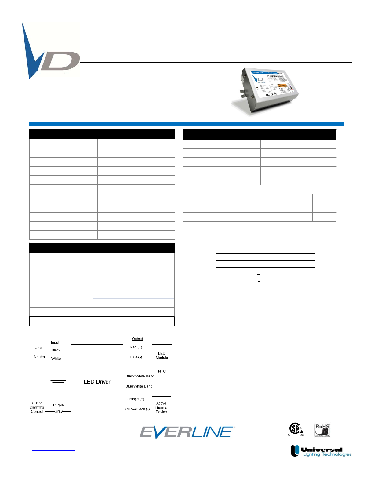
0‐10VAnalogDimmingInterface
Analog0to10vDC VoltageControl
‐UseViolet(+)&Gray(‐)forconnectionto0‐10vDC.
0.7
0.8
OutputCurrentDimmingCurve
‐10v=maximumoutput,0v=minimumoutput
‐Driverprotectediflinevoltageisapplied.
‐WiringViolet&Graytogetherprovidesmin.light
output.
‐CappingViolet&Grayseparatelyprovides100%
lightoutput.
‐0‐10VinterfacecanbewiredasClass1orClass2
0
0.1
0.2
0.3
0.4
0.5
0.6
OutputCurrent(A)
•Driverwillsourceamaximumof250uAforcontrol
needs.
012345678910
0‐10VControlVoltage
Page2of3
www.unvlt.com
February6,2014
Applicationandoperationperformancespecificationinformationsubjecttochangewithoutnotification.