manuals.online logo
Brands
  1. Home
  2. •
  3. Brands
  4. •
  5. Universal Tool
  6. •
  7. Paint Sprayer
  8. •
  9. Universal Tool UT59A Specifications

Universal Tool UT59A Specifications

Read these instructions carefully before installing, operating,
servicing or repairing this tool. Keep these instructions in a safe
accessible place.
Important
Includes - Foreseen Use, Work Stations, Putting Into Service, Operating,
Dismantling, Assembly and Safety Rules
Operator Instructions
Manufacturer/Supplier Product Type RPM
Cycles Per Min
Model No/Nos Serial No
Product Nett Weight
lbs
Kg
Recommended Use Of
Balancer Or Support
Recommended Hose Bore
Size - Minimum
Recommended Max.
Hose Length
Ins M/M Ft M
No
Page No 1
1mm Spray Gun - Touch Up
Gravity Feed Cup (125cc)
UT59A
0.73
0.33 5/16 8 30 10
N/A
Universal Air Tool Company Limited
Unit 8
Lane End Industrial Park
High Wycombe
Bucks
HP14 3BY
Work Stations
The spray gun should only be used as a handheld hand-operated
device. It is always recommended that the spray gun is used when
standing on the solid floor. It can be used in other positions provided the
spray gun is kept near vertical and the operator has a firm grip and
footing. Any work station must take account that the liquid being
sprayed should not be breathed in and the liquid can be highly
flammable and spraying should never be undertaken near naked flames
or hot surfaces. Do not smoke. It
should also takeaccount that not all of
the liquid being sprayed will be
applied to the object being sprayed
and account must be taken that this
Foreseen Use of Tool
This model is a mini touch-up with an external mix, high capacity spray
gun, designed for high quality production spraying of paint and other
finishing material from a gravity plastic cup. Spray all of small area,
touch-up, detail and miniature artwork spraying.
The material inlet is located directly on the top of the spray gun and the
air inlet is located at the bottom of the spray gun handle.
The fluid control knob located at the rear of the spray gun, the pattern
control knob is located at the left side of the spray gun.
Tel No Fax No(01494) 883300 (01494) 883237
Noise Level Sound Pressure Level TBA dB(A)
Test Method Tested in accordance with ISO
Standard 3744
Sound Power Level TBA dB(A)
N/A
Vibration Level
Test Method Vibration testing not required for a
spray gun
N/A Metres / Sec²
Operating
Prior to shipment, this gun was
treated with an anti corrosive agent,
before using this gun make sure that it
is carefully flushed with thinners.
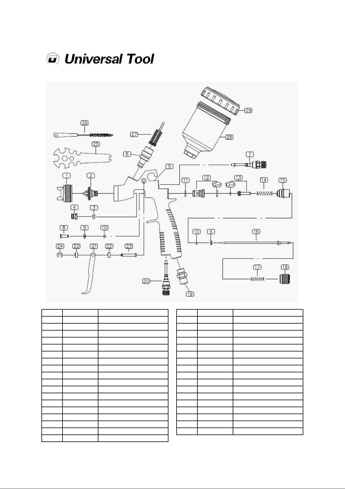
To use the gun, tighten the air cap
with its stamping number in an
upward direction. Attach material cup to the gun. Attach an air supply
line to the ¼” BSP air inlet. Check for the correct tightening of nut (4) so
that no air will escape but air valve stem (16) still slides. Caution:
Never point spray gun at yourself or any other person. Accidental
discharge of material may result in serious injury. Adjust air pressure to
spray gun. Caution: Do Not exceed 100 psi. Depress spray gun
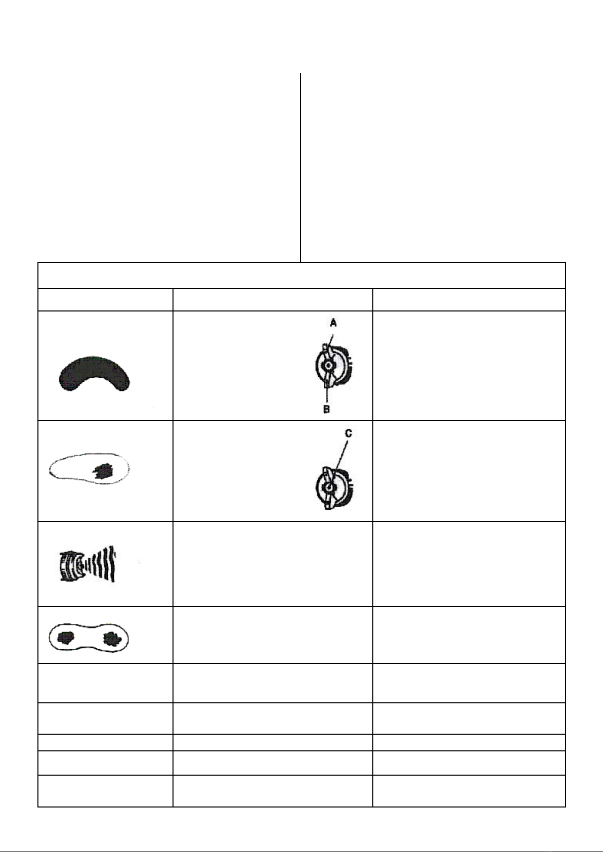
trigger to spray material. To adjust the amount of material released
(density of fan spray), turn the fluid control knob (7) (counter clockwise
to increase, or clockwise to decrease). To adjust the width of fan spray,
turn the pattern control knob (15) (counter clockwise to increase, or
clockwise to decrease). To adjust the air quality turn the Air Volume
control knob (20) (counter clockwise to increase, or clockwise to
decrease). Note: Care should be exercised when handling spray gun
to avoid damage to the orifice of the air cap and tip of fluid nozzle,
damage to these parts will result in irregular spray patterns
Personal Safety Equipment
Use - Safety Glasses
Yes
Use - Safety Gloves
Yes
Use - Safety Boots
Use - Breathing Masks
Yes
Use - Ear Protectors
Air Pressure
Recommended Working 2.06 bar 30 psi
Recommended Minimum n/a bar n/a psi
Maximum 2.76 bar 40 psi
Page No 2
Troubleshooting
Defective Pattern Likely Cause Suggested Remedy
Dried material is clogging side-port “A” and
causing side-port “B” to blow spray towards
the clogged side.
Soak side-ports in thinner to clean clog. Do not poke any open-
ing with metal objects.
Dired material at fluid nozzle “C” restricts air
flow.
Loose air nozzle
Air Pressure set too high.
Remove air nozzle. Wipe off fluid tip using a cloth soaked in
thinner or soft brush.
Fasten nozzle securely.
Reduce air pressure.
Spitting, irregular or fluttering spray Fluid nozzle cracked or worn.
Leak at thread of fluid nozzle.
Leak at fluid needle.
Needle Packing worn out.
Insufficient fluid in cup.
Vent hole in container cover clogged.
Tighten or replace.
Tighten fluid nozzle.
Tighten compression nut assembly or replace needle packing.
Replace packing.
Fill cup with fluid.
Clean out vent.
Split spray pattern. Air Pressure too high. Turn pattern knob c/w to decrease fan width. Turn fluid needle
adjusting nut c/w to increase fluid flow.
Unatomised or splattered spray. Material too heavy.
Insufficient air pressure.
Fluid pressure too high.
Dried material on tip of fluid nozzle or air jets of air cap.
Thin material or use larger orifice fluid nozzle set.
Increase pressure to within limit.
Reduce pressure.
Clean.
Inadequate air delivery Air needle partially closed.
Dried material in air jets of air cap.
Obstruction in air line.
Open control knob.
Clean.
Remove obstruction.
Excessive fog Air pressure too high for viscosity of fluid. Reduce air pressure and/or open fluid control knob.
Material leaking from fluid inlet cup Loose cup or foreign substances on/between cup thread and fluid
inlet.
Tighten and clean or replace it.
Material leak from nozzle when trigger is
released.
Worn fluid needle.
Dried material in tip of nozzle.
Loose packing nut.
Replace.
Clean.
Tighten Needle packing nut by turning counterclockwise.
Dismantling & Assembly Instructions
It is important that the spray gun is cleaned after daily use. Cleaning is accomplished by
spraying an appropriate solvent or thinners through the system. Wipe the exterior of
the spray gun with a solvent soaked cloth or use the provided brush to remove any
accumulated material.
Exchange of nozzle set
When changing to another nozzle, make sure that the complete nozzle set is
changed. A set comprises of air cap, paint nozzle, and fluid needle.
Assemble fluid nozzle before putting in fluid needle.
Cleaning
Empty any material from the gravity feed cup and replace with a suitable solvent.
Operate trigger until material traces have disappeared and gun is thoroughly clean.
Wipe gun exterior with a solvent dampened cloth or use provided brush.
Note: If fluid nozzle (2) is to be removed for thorough cleaning squeeze trigger to
prevent damaging the fluid needle tip (7) when unscrewing nozzle.
Caution: Always exercise extreme care when using any solvent or thinners. Never
clean gun near fire, flames or any source of heat or sparks. Properly dispose of used
cleaning material.
Caution: Do Not soak entire spray gun insolvent or thinners for a long period of time
as this will destroy lubricants and possibly makes motion unsmooth.
Never use lye or caustic alkaline solutions for cleaning; such solutions will attack the
aluminium alloy parts of the gun.
Important: Make certain that the air cap and fluid nozzle are kept clean at all times. If
necessary, remove these two components and soak them in solvent.
Do Not use metal instruments to clean air cap or fluid nozzles as an irregular spray
pattern may result.
After a thorough cleaning of the gun, the following lubrication procedures must be
observed to ensure affective high quality performance of the spray gun. Lubricate
working points (13) with straight mineral oil or caster oil. Periodically place a few drops
of oil on tapered sections of fluid nozzle (2) to ensure easy operation of the air cap.
When spraying water bases materials coat fluid nozzle inside and out with straight
mineral oil after use. Outer diameter of needle sleeve (7) of fluid needle assembly must
be lubricated occasionally with straight mineral oil.
UT59A Spray Gun - Touch Up Gravity Feed
Page No 3
May 2008 Ver 1.10
Ref No Part No Description
1 9920000401 Air Cap
2 9930000401 Fluid Nozzle 0.8
2 9930000402 Fluid Nozzle 1.0
2 9930000404 Fluid Nozzle 1.2
3 9000005100 Needle Packing Set
4 9000005200 Needle Packing Seat
5 9910000800 Body Set
6 9000005300 Fluid Nipple
7 9000005401 Pattern Adj.Set
8 9000005500 Air Valve Shaft
9 9000005600 Packing Holder
10 9000005700 O-Ring
11 9000005800 Gasket
12 9000005900 Air Valve Seat Set
12-1 9000005910 O-Ring
13 9000006000 Air Valve Seat Set
13-1 9000005700 O-Ring
14 9000006100 Air Valve Spring
Ref No Part No Description
15 9000006200 Fluid Adj.Guide Set
16 9940000201 Fluid Needle 0.8
16 9940000202 Fluid Needle 1.0
16 9940000204 Fluid Needle 1.2
17 9000006300 Needle Spring
18 9000006401 Fluid Adj.Knob
19 9000006500 Air Inlet Nipple
20 9000006601 Air Adj.Set
21 9000006700 Trigger
22 9000006800 Gasket
23 9000001900 Trigger Stud
24 9000002000 E-Ring
25 9710001400 Spanner
26 9720002100 Brush
27 9750000100 Material Sleeve
28 9810000120 Plastic Cup
29 9810000130 Cover
Distributor
Notes
Page No 8
Declaration of Conformity
Universal Air Tool Company Limited
Unit 8, Lane End Industrial Park, High Wycombe, Bucks, HP14 3BY, England
declare under our sole responsibility that the product
Model UT59A Touch Up Spray Gun, Serial Number
to which this declaration relates is in conformity with the following standard(s) or other normative document(s)
EN792 (Draft), EN292 Parts 1 & 2, ISO 8662/1
following the provisions of 89/392/EEC as amended by 91/368/EEC & 93/44/EEC Directives
Place and date of issue Name and signature or equivalent marking of authorised person
Lane End D.H.Moppett (Man. Director)
This document may not be copied wholly or in part by anyone without the consent of the Directors of Universal Air Tool Company Limited
©Copyright of Universal Air Tool Company Limited, established in the United Kingdom, 1994
Designed & Written in the U.K.
Safety Rules
Do not assume that you are totally familiar with this unit until after
having read all warning tags, labels, nameplates, instruction sheets and
any other explanatory material completely and thoroughly. To avoid
accidents, this should be done by all persons before attempting to
operate, assemble or disassemble the gun or any other part of the
system.
Before disassembly or removal of any part of the gun or attached
components; shut off compressor, release pressure by depressing the
trigger and disconnect power source.
Never assume system pressure is zero!
Protect all lines against damage. Avoid Risk. If uncertain as to safe
conditions of hoses, replace with the same type of a suitable
replacement. (Do Not Repair).
To avoid creating an explosive atmosphere, work only in a well
ventilated area.
Use of a face mask is recommended to prevent inhalation of toxic
material.
Do Not attempt to unclog (back flush) spray gun by squeezing trigger
while holding your finger in front of the fluid nozzle.
Pressure may vary according to viscosity of material used. Maximum
working pressure is 40 psi.
Do not exceed pressure limit of gun or any other component
in system.
Prior to daily operation, make certain that all connections and fittings are
secure.
Check hose and all connections for weak or worn condition that could
render system unsafe. All replacement components such as hose or
fittings must have a working pressure equal to or greater than system
pressure.
Recommended spray distance 8” to 10”.
Warning
Halogenated hydrocarbon solvents for example: 1,1,1- trichloroethane
and methylene chloride- can chemically react with the aluminium in this
gun and cause an explosion hazard. Read the label or data sheet for the
material you intend to spray. Do not use spray material containing these
solvents with this spray gun.
Accessories
ARTHUR PATERSON

Other Universal Tool Paint Sprayer manuals

Universal Tool UT58A-14 Specifications

Universal Tool

Universal Tool UT58A-14 Specifications

Universal Tool UT57A Specifications

Universal Tool

Universal Tool UT57A Specifications

Popular Paint Sprayer manuals by other brands

WAGNER FINISH CONTROL 3500 operating manual

WAGNER

WAGNER FINISH CONTROL 3500 operating manual

Loctite 3609 Technical data sheet

Loctite

Loctite 3609 Technical data sheet

PMC PH Electrical diagrams

PMC

PMC PH Electrical diagrams

WAGNER ProSpray 3.29 operating manual

WAGNER

WAGNER ProSpray 3.29 operating manual

WALTHER PILOT PILOT WA 450 operating instructions

WALTHER PILOT

WALTHER PILOT PILOT WA 450 operating instructions

Durr EcoGun 651 Operation manual

Durr

Durr EcoGun 651 Operation manual

SATA Vario top spray operating instructions

SATA

SATA Vario top spray operating instructions

Rogers Sprayers EcoFoil EF1000 Assembly and operation manual

Rogers Sprayers

Rogers Sprayers EcoFoil EF1000 Assembly and operation manual

Anest Iwata WA 200 Installation, use & maintenance instruction manual

Anest Iwata

Anest Iwata WA 200 Installation, use & maintenance instruction manual

Titan LX-80 II instruction sheet

Titan

Titan LX-80 II instruction sheet

Meec tools 082-207 operating instructions

Meec tools

Meec tools 082-207 operating instructions

FujiFilm T-75G instructions

FujiFilm

FujiFilm T-75G instructions

HDX 1501HDXA user manual

HDX

HDX 1501HDXA user manual

Nederman SB750 instruction manual

Nederman

Nederman SB750 instruction manual

Barnstead MaxQ 2000 Series manual

Barnstead

Barnstead MaxQ 2000 Series manual

DEMA 294CTDM installation instructions

DEMA

DEMA 294CTDM installation instructions

Toro 41582 Operator's manual

Toro

Toro 41582 Operator's manual

Pyranha SPRAYMASTER SM55 user manual

Pyranha

Pyranha SPRAYMASTER SM55 user manual

manuals.online logo
manuals.online logoBrands
  • About & Mission
  • Contact us
  • Privacy Policy
  • Terms and Conditions

Copyright 2025 Manuals.Online. All Rights Reserved.