Uplift Desk KIT-KBT-Multi User manual

Mechanism Package Keyboard Tray Package
Step 2
If you are not using the Track Spacer Kit, place the Track un-
derneath your desktop in the desired location, with about 1/2”
from the front edge of the desktop to the front edge of the
Track.* Using the Track as a template, mark the center of the
holes with a pencil (ten holes on a 21” Track and eight holes on
an 11” Track).
*Caution: If you are attaching the Track to
a desktop with a curved front edge, make
certain there is 1-1/2” from the front edge
of the desktop to the front edge of the
Track. This will prevent the screws from
piercing through the top of the desktop.
(see g. 1)
To make this step a little easier, if you own a drill, you can make
pilot holes. Use a 1/8” diameter drill bit and, ensuring that you
DRILL NO DEEPER THAN 1/2”, drill pilot holes where you’ve
made your marks on your desktop.
Note: Some UPLIFT desktops are built with metal support bars
embedded in the bottom side. They are clearly visible when
looking under the desk. Be mindful of where your Track will be
going, and be careful not to drill or screw into these support
bars. The Track can be installed directly over a support bar;
please refer to the note in Step 3 to show you how to do this.
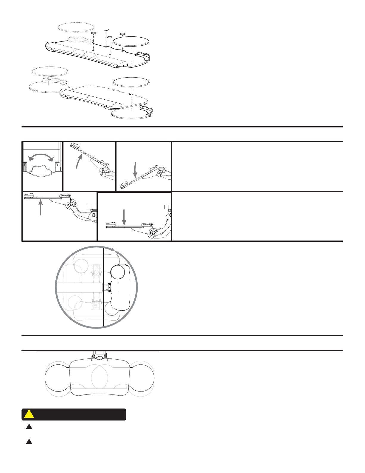
Step 1
The Mechanism will come shipped already slid into a Track. Un-
wrap the plastic and unfold the cardboard ap at the back, then
hold the Mechanism by the base as shown, and slide it off the
track.
A shipping pin or strap will keep the Mechanism from activating
during this process.
Adhesive pads
(optional. qty 4)
Wood screws
(qty 12)
Machine screws
(qty 4. Big trays only)
Front bumper
Back bumper
Wire clip
Acorn nut
(qty 4)
Cord catcher
Mechanism
Track
(11’’ and 21’’ tracks
are included.)
Keyboard Tray
(style varies by model purchase)
or
Track Spacer Kit
(optional. sold separately)
Before you begin the installation process, determine which of the included
track lengths you will be using, 11” or 21”. If you decide to use the 21” track
and need to mount it over the desk frame crossbars, you will need to use
the Track Spacer Kit (sold separately). Instructions for how to use the Track
Spacer Kit are included in its packaging.
A Note Before You Begin:
Keyboard Tray System with Quick Adjust Mech
SKU: KBT009
g 1.
Mouse pad
Package Contents

Step 4
Line up the Mechanism with the grooves on the Track, and slide
it into place.
Leave the front portion of the Mechanism extended past the front
edge of the desktop so that you can attach your Tray.
Please note: the Mechanism will not adjust up or down until the
Tray has been attached and the shipping pin or strap has been
removed (see step 6).
Step 5
For the Big Ultra-Thin and Big Standard Trays: Attach the Tray to
the Mechanism by lining up the holes in the Tray with the holes on
the Mechanism, and secure by inserting the four Machine screws
through the holes in the top of the Tray, and attaching the four
Acorn nuts onto them from below.
For the Switch Tray: Attach the Tray to the Mechanism by lining
up the integrated screws on the bottom of the Tray with the holes
on the Mechanism; secure in place by attaching the four Acorn
nuts onto the screws from below.
Step 7
Finally, lower the Tray and slide the assembly back on the Track. To
adjust the height of the Tray, push down on the back of the tray
while lifting the front in the same manner as used to remove the
shipping pin. Install the Front bumper using three Wood screws.
Note: You may want to drill two pilot holes for the ends of the
Front bumper using the directions from Step 2.
Step 6
The Mechanism ships with either a metal pin or plastic tie installed,
which keeps it secure during shipment. To remove the pin, lift up
on the front of the Tray while pushing the back of the Tray down
in a twisting motion to allow the pin to be pulled out. To remove
the plastic tie, just cut it and remove.
Step 3
Using eight Wood screws for the 21’’ track or six Wood screws for
the 11’’ track, attach the Track to the underside of the desktop. Use
one more screw to attach the Rear bumper, as shown.
Note: If you are mounting your Track on a desktop with a
center support bar and you are not using a Track Spacer Kit,
you can attach the Back bumper through either of the outside
holes, as shown, to avoid hitting the bar. You can also shift your
Track slightly to the left or right.

CAUTION: Read all instructions before assembly. Failure to assemble or operate properly may
result in damage or personal injury. Retain manual for future reference.
CAUTION: Maximum weight limit for all keyboard trays is 10 lb. Do not overload.
CAUTIONS & WARNINGS
!
!
!
Rotate
The Tray rotates at the point where the Mechanism attaches to
the Track. The Tray can rotate a full 360 degrees (unless it is ob-
structed by something underneath the desktop).
Tilt
To adjust the tilt of the Tray, turn the knob at the center of the
tray. This will allow you to tilt the Tray up and down.
Height
To adjust the height of the Tray, push down on the back of the
Tray while lifting the front in a twisting motion. Then raise or
lower to the desired height.
Adjustments applicable to all Keyboard Trays
Adjustment applicable to the Switch Keyboard Tray only
360°
Swapping sides for your mousing platform
The mousing platform on the Switch tray can slide from the
right or left side. It can also be adjusted forward and back-
wards.
Step 8
For the Big Ultra-Thin and Big Standard Trays: Place the Mouse
pad and Cord catcher on the desired side. The non-slip Adhesive
pads keep keyboards from sliding can be placed over the heads of
the machine screws, or in any other spot on the tray. Use the Wire
clip anywhere you need to secure loose wires to prevent snags.
For the Switch Tray:
Slide the mouse platform to desired side and
place the Mouse pad and Cord catcher onto the platform. The non-
slip pads can be placed in any position on the tray. Use the Wire
clip anywhere to secure loose wires to prevent snags.

512-614-3152
800-349-3839
upliftdesk.com
Work Better. Live Healthier
Copyright Notice: This guide is a component of this UPLIFT Desk accessory. This guide is a part of the scope of delivery, even if the item is resold.
This guide is also available on the UPLIFT Desk website: upliftdesk.com. Excerpts or copies may not be forwarded to third parties or used in any other
published form without the prior written consent of UPLIFT Desk. These instructions are subject to United States copyright law.
©
SAVE THESE INSTRUCTIONS
Study this manual carefully. If this product is sold, please provide this
manual to the buyer, installers, or support personnel operating the product.
®
AI-KBT009-1.0
This manual suits for next models
5
Table of contents
Other Uplift Desk Computer Accessories manuals