UPOWER Ecoline UE-48LI3750I User manual

UE-48LI3750I ESS Unit
User Manual

UE-48LI3750I ESS Unit User Manual
Content
SAFETY PRECAUTIONS.............................................................................................................................. 1
PREFACE.....................................................................................................................................................2
1 INTRODUCTION..................................................................................................................................... 3
1.1 BRIEF INTRODUCTION......................................................................................................................................................... 3
1.2 PRODUCT PROPERTIES........................................................................................................................................................ 3
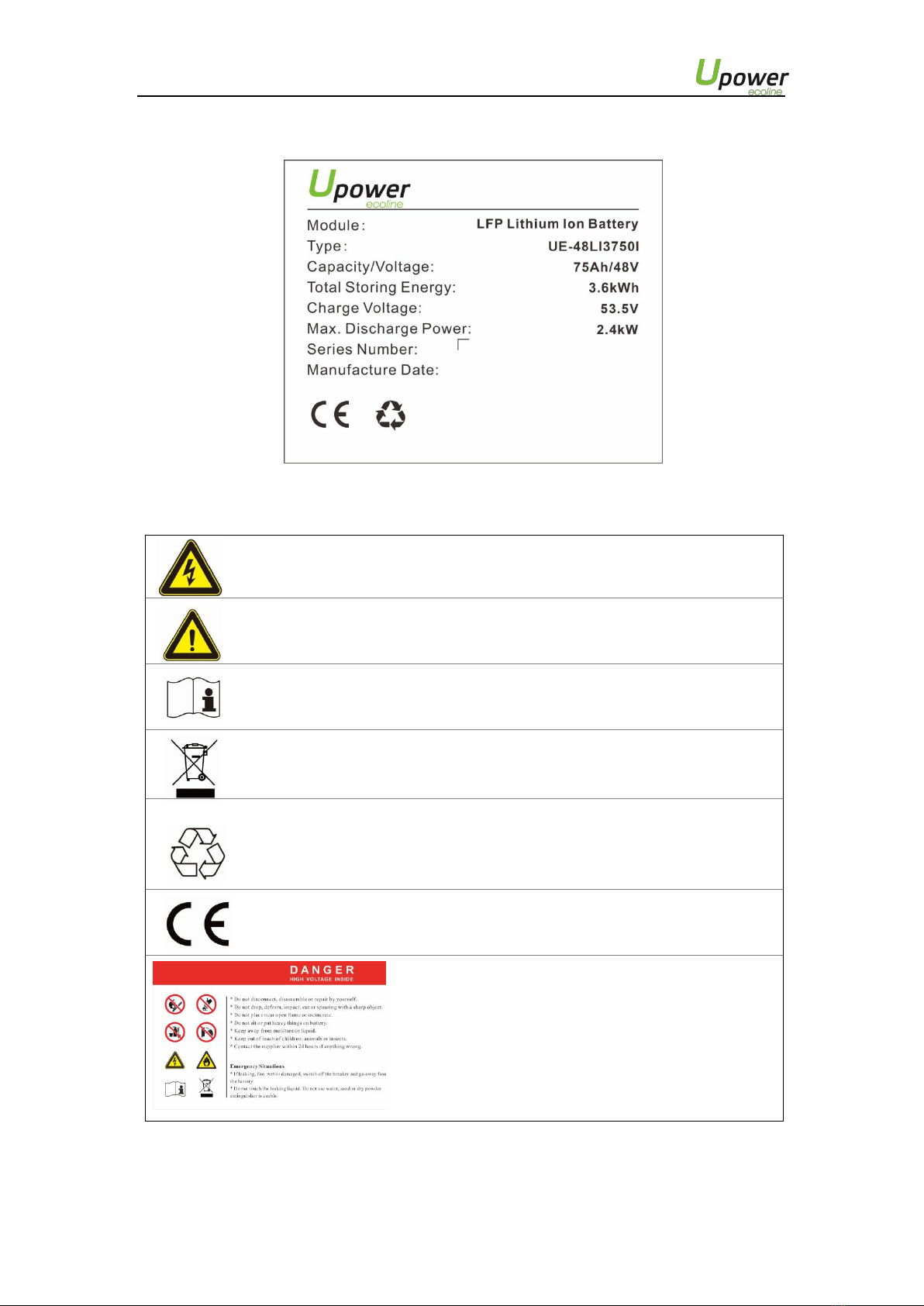
1.3 PRODUCT IDENTITY DEFINITION......................................................................................................................................... 4
2 PRODUCT SPECIFICATION..................................................................................................................... 5
2.1 SIZE AND WEIGHT...............................................................................................................................................................5
2.2 PERFORMANCE PARAMETER............................................................................................................................................. 5
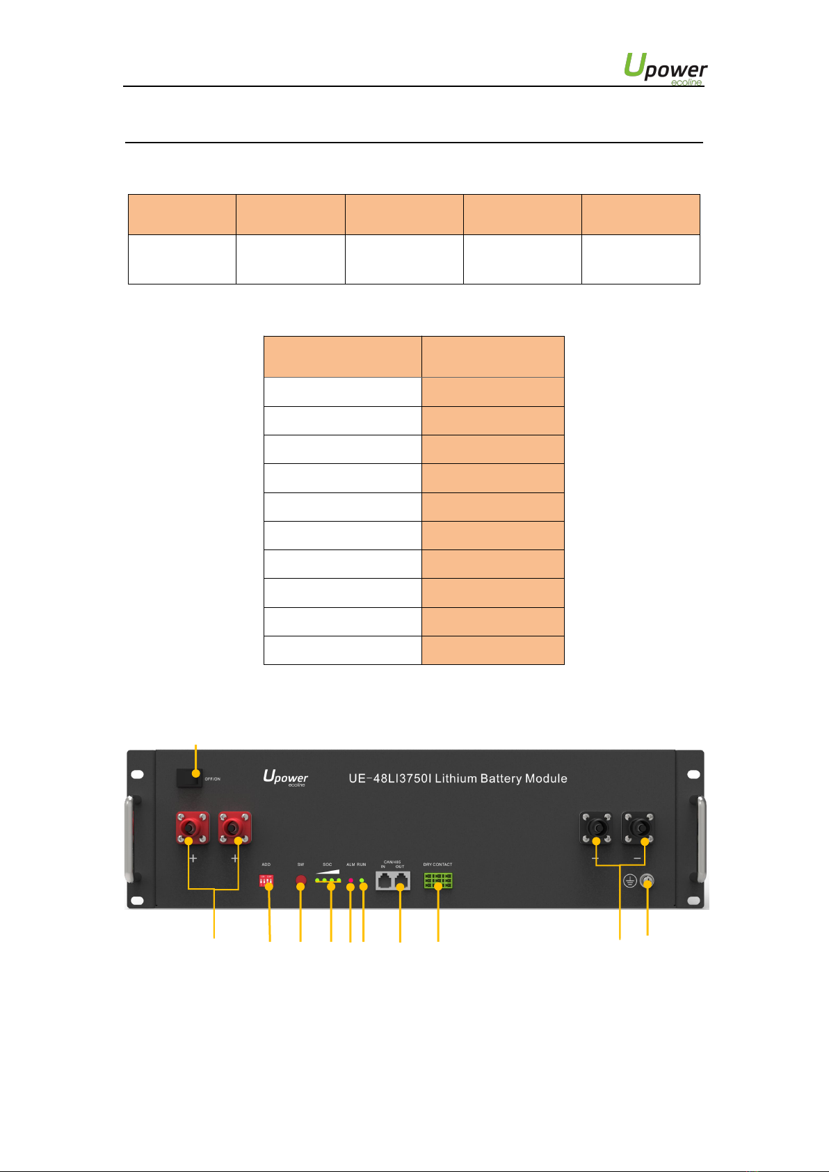
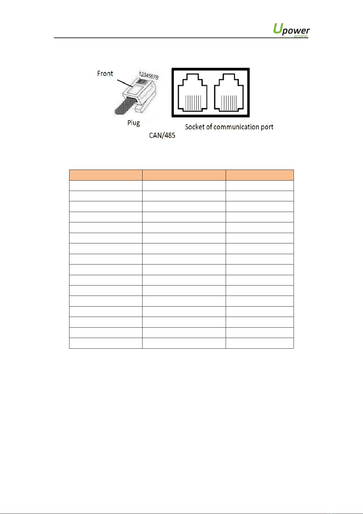
2.3 INTERFACE DEFINITION...................................................................................................................................................... 5
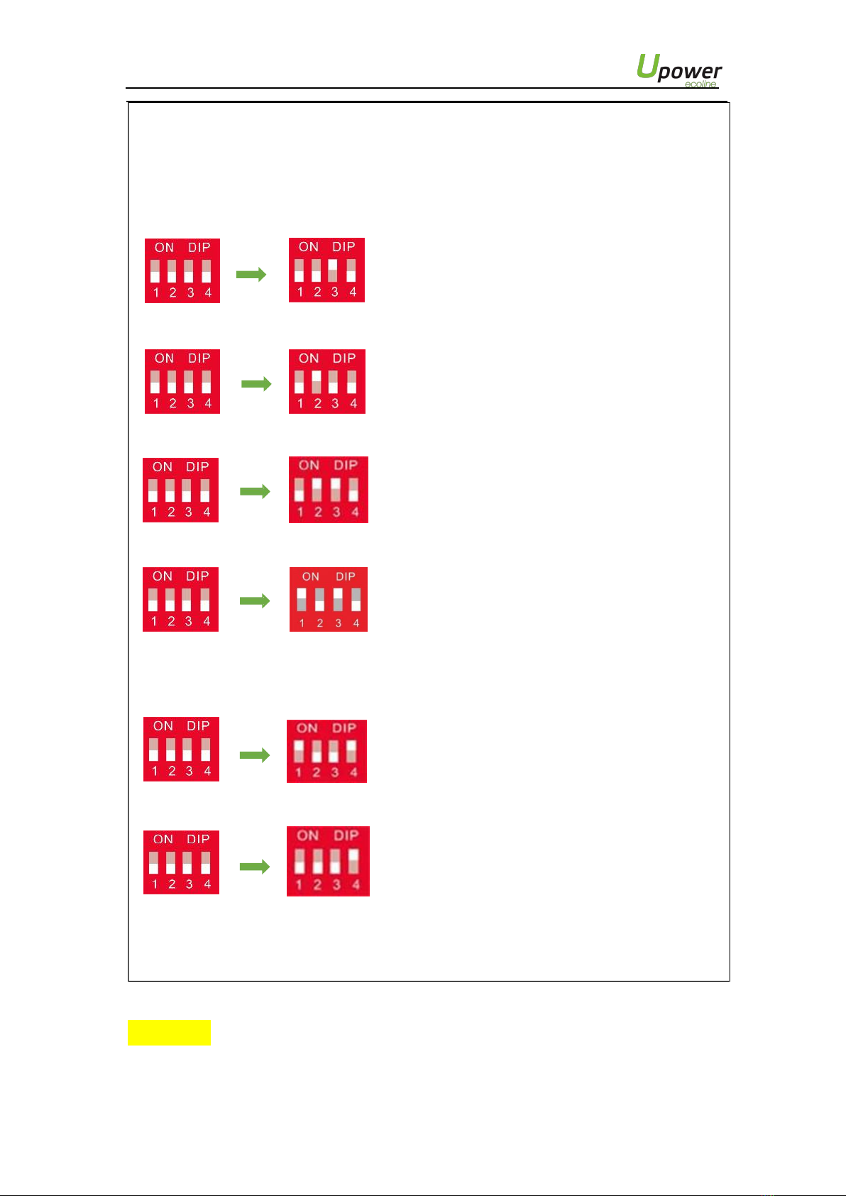
2.3.1 DIP switch definition and description.....................................................................................
6
2.4 BATTERY MANAGEMENT SYSTEM(BMS)................................................................................................9
2.4.1 Voltage Protection.................................................................................................................
9
2.4.2 Current Protection..................................................................................................................
9
2.4.3 Temperature Protection.......................................................................................................
10
2.4.4 Other Protection..................................................................................................................
10
3 INSTALLATION AND CONFIGURATION...............................................................................................11
3.1 PREPARATION FOR INSTALLATION.................................................................................................................................. 11
3.1.1 Environmental requirements...............................................................................................
11
3.1.2 Tools and data.....................................................................................................................
11
3.1.3 Technical preparation..........................................................................................................
12
3.1.4 Unpacking inspection...........................................................................................................
12
3.1.5 Engineering coordination.....................................................................................................
14
3.2 EQUIPMENT INSTALLATION............................................................................................................................................. 14
3.2.1 Installation preparation........................................................................................................
15
3.2.2 Mechanical installation........................................................................................................
15
3.2.3 Electrical installation............................................................................................................
16
3.2.4 Battery parameter settings on the inverter.........................................................................
18
4 USE, MAINTENANCE AND TROUBLESHOOTING................................................................................ 19
4.1 BATTERY SYSTEM USAGE AND OPERATION INSTRUCTIONS.............................................................................................19
4.2 ALARM DESCRIPTION AND PROCESSING.........................................................................................................................20
4.3 ANALYSIS AND TREATMENT OF COMMON FAULTS........................................................................................................20

1
UE-48LI3750I ESS Unit User Manual
Safety Precautions
Warning
Please do not put the battery into water or fire, in case of explosion or any other situation
that might endanger your life.
Please connect wires properly while installation, do not reverse connect.
To avoid short circuit, please do not connect positive and negative poles with conductor on the
same device.
Please avoid any form of damage to battery, especially stab, hit, trample or strike.
Please shut off the power completely when removing the device or reconnecting wires
during the daily use or it could cause the danger of electric shock.
Please use dry powder extinguisher to put out the flame when encountering a fire hazard,
liquid extinguisher could result in the risk of explosion.
For your safety, please do not arbitrarily dismantle any component in any circumstances. The
maintenance must be implemented by authorized technical personnel or our company’s
technical support. Device breakdown due to unauthorized operation will not be covered under
warranty.
Caution
Our product have been strictly inspected before shipment. Please contact us if you find any
abnormal phenomena such as device outer case bulging.
The product shall be grounded properly before use In order to ensure your safety.
To assure the proper use please make sure parameters among the relevant device are
compatible and matched.
Please do not mixed-use batteries from different manufacturers, different types and
models, as well as old and new together.
Ambient and storage method could impact the product life span, please comply with the
operation environment instruction to ensure device works in proper condition.
For long-term storage, the battery should be recharged once every 6 months, and the
amount of electric charge shall exceed 80% of the rated capacity.
Please charge the battery in 18 hours after it fully discharged or over-discharging protection
mode is activated.
Formula of theoretical standby time: T=C/I (T is standby time, C is battery capacity, I is total
current of all loads).

2
UE-48LI3750I ESS Unit User Manual
Preface
Manual declaration
UE-48LI3750I lithium iron phosphate battery energy storage system can provide energy storage
for photovoltaic power generation users through parallel combination. Our product can store
extra electricity into battery from photovoltaic power generation system in daytime and supply
stable power to user’s equipment as power backup at nighttime or any time when needed. It can
improve the efficiency of photovoltaic power generation and increase the electric power efficiency
by peak load shifting.
This user manual details the basic structure, parameters, basic procedures and methods of
installation and operation and maintenance of the equipment.

UE-48LI3750I ESS Unit User Manual
3
1 Introduction
1.1
Brief Introduction
UE-48LI3750I lithium iron phosphate battery system is a standard battery system unit,
customers can choose a certain number of UE-48LI3750I according to their needs, by
connecting parallel to form a larger capacity battery pack, to meet the user's long-term
power supply needs. The product is especially suitable for energy storage applications
with high operating temperatures, limited installation space, long power backup time and
long service life.
1.2
Product Properties
UE-48LI3750I energy storage product’s positive electrode materials are lithium iron
phosphate, battery cells are managed effectively by BMS with better performance, the
system’s features as below:
Comply with European ROHS, Certified SGS, employ non-toxic, non-pollution
environment-friendly battery.
Anode materials are lithium iron phosphate (LiFePO4), safer with longer life span.
Carries battery management system with better performance, possesses protection
function like over-discharge, over-charge, over-current, abnormal temperature.
Self-management on charging and discharging, Single core balancing function.
Intelligent design configures integrated inspection module.
Flexible configurations allow parallel of multi battery for longer standby time.
Self-ventilation with lower system noise.
Less battery self-discharge, then recharging period can be up to 10 months during the
storage.
No memory effect so that battery can be charged and discharged shallowly.
With wide range of temperature for working environment, -20℃~ +55 ℃,
circulation span and discharging performance are well under high temperature.
Less volume, lighter weight.

UE-48LI3750I ESS Unit User Manual
4
1.3
Product identity definition
Figure1-1 Battery Energy Storage System nameplate
Battery voltage is higher than safe voltage, direct contact
with electric shock hazard.
Be careful with your actions and be aware of the
dangers.
Read the user manual before using.
The scrapped battery cannot be put into the garbage can
and must be professionally recycled.
After the battery life is terminated, the battery can
continue to be used after it recycled by the professional
recycling organization and do not discard it at will.
This battery product meets European
directive requirements.
Dangerous goods warning label on the top of the
battery module

UE-48LI3750I ESS Unit User Manual
5
2 Product Specification
2.1
Size and Weight
Table 2-1 UE-48LI3750I Device size
Product
Nominal
Voltage
Nominal
Capacity
Dimension
Weight
UE-
48LI3750I
DC48V
75Ah
480×360×130mm
≈31kg
2.2
Performance Parameter
Table 2-2 UE-48LI3750I performance parameter
Item
UE-48LI3750I
Parameter value
Nominal Voltage(V)
48
Work Voltage Range(V)
42~54
Nominal Capacity(Ah)
75
Nominal Energy(kWh)
3.6
Nominal Power(kW)
1.8
Max Power(kW)
2.4
1S Peak Power(kW)
2.64
1S Peak Current(A)
55
Charging Current(A)
37.5
Discharge Current(A)
37.5
2.3
Interface Definition
This section elaborates the interface functions of the front interface of the device.
1
Figure2-1 The sketch of interface.
2
6
4
5
3
7
8
9
10
11

UE-48LI3750I ESS Unit User Manual
6
Table 2-3 Interface Definition
Item
Name
Definition
1
Power switch
OFF/ON,
must be in the "ON" state when in use
2
Ground
connection point
Shell ground connection
3
Positive socket
Battery output positive or parallel positive line
4
Negative socket
Battery output negative or parallel negative line
5
SW (battery
wake/sleep
switch)
When the "OFF/ON" switch button is in the ON state, press
and hold this button for 3 seconds to put the battery into the
power-on or off state.
6
SOC
The number of green lights on shows the remaining battery
power. See Table 2-3 for details.
7
ALM
Red light flashing when an alarm occurs, red light always on
during protection status. After the condition of trigger
protection is relieved, it can be automatically closed.
8
RUN
Green light flashing during standby and charging mode.
Green light always on when discharging.
9
CAN/485
Communication cascade port, support CAN/ RS485
communication (factory default CAN communication)
10
DRY CONTACT
/
11
ADD
DIP switch
2.3.1 DIP switch definition and description
Table 2-4 Interface Definition
DIP switch position (master communication protocol and baud rate selection)
#1
#2
#3
#4
Define different protocols;
Distinguish between master and slave
Baud rate selection
OFF:CAN: 500K,485: 9600
ON:CAN: 250K,485: 115200
DIP switch description:
When the batteries are connected in parallel, the master communicates with the slaves through
the CAN interface. The master summarizes the information of the entire battery system and
communicates with the inverter through CAN or 485.

UE-48LI3750I ESS Unit User Manual
7
1. If the master is the latest UE-48LI3750I battery with DIP switch:
(1)The communication cable from the master CAN IN to the inverter comm port should be the
correct one.
(2)When the battery works with GOODWE、Solis、LUX、Sofar、DEYE、VICTRON、IMEON、
Sungrow、SMA、RENAC、DELIOS、SAJ(CAN Comm) ,before starting the battery,you need
put the master DIP switch "# 3" to the "ON" position (to the top), then turn on the batteries.
Master Setting 1
(3)If the battery communicates with the Axpert-king/VMIII/MAX,Infinisolar,Growatt SPH/SPA(CAN
comm)、GMDE、turn the master DIP switch "#2" to "ON" position.
Master Setting 2
(4)If the battery communicates with the Growatt SPF HVM-P/ES/WPV by RS485
communication, turn the master DIP switch "#2" and "#3" to "ON".
Master Setting 3
(5)If the battery communicates with the Schneider Conext Series, turn the master DIP switch
"#1" and "#3" to "ON".
Master Setting 4
(6)When you setup the master DIP as setting 1~4,all the slaves keep the DIP 0000,no need
change.
(7)If the battery module is in communication with the ICC by 485 communication, turn the
master DIP switch "#1" and "#4" to "ON".
Master Setting 5
the DIP switch of slaves need to turn the “#4” to “ON” at the same time while the master is
setting 5.
Slave Setting 2
(8)If the energy storage system has only one UE-48LI3750I, it is the master itself, and still
follow the above steps.
Note: For more information of matching inverter brands, please subject to the latest document
<The list of compatibility between ESS and Inverters >.
Caution:The DIP switch mode in case (7),1001 is only for ICC(a special communication
device of some no-communication inverter), it’s a special firmware in BMS,different from general
firmware,so if customers want to use ICC,please contact us to confirm.

UE-48LI3750I ESS Unit User Manual
8
Figure 2-2 CAN/485 interface definition
Table 2-4 Pin Definition
Foot position
Color
Definition
PIN1
Orange/white
485A
PIN2
Orange
XGND
PIN3
Green/white
485B
PIN4
Blue
CANH
PIN5
Blue/white
CANL
PIN6
Green
Reserve
PIN7
Brown/white
XIN
PIN8
Brown
Reserve
PIN9
Orange/white
Reserve
PIN10
Orange
XGND
PIN11
Green/white
Reserve
PIN12
Blue
CANH
PIN13
Blue/white
CANL
PIN14
Green
Reserve
PIN15
Brown/white
XOUT
PIN16
Brown
Reserve

UE-48LI3750I ESS Unit User Manual
9
Table 2-5 LED status indicators
Battery
Status
SOC
LED1
LED2
LED3
LED4
ALM
RUN
Shutdown
/
off
off
off
off
off
off
Standby
75%≤SOC≤100%
●
●
●
●
off
Flashing
50%≤SOC<75%
●
●
●
off
off
Flashing
25%≤SOC<50%
●
●
off
off
off
Flashing
5%<SOC<25%
●
off
off
off
off
Flashing
0%<SOC≤5%
●
off
off
off
Flashing
Flashing
SOC=0
off
off
off
off
Flashing
/●
Flashing
Charging
SOC=100%
●
●
●
●
off
Flashing
75%≤SOC<100%
●
●
●
Flashing
off
Flashing
50%≤SOC<75%
●
●
Flashing
off
off
Flashing
25%≤SOC<50%
●
Flashing
off
off
off
Flashing
0%<SOC<25%
Flashing
off
off
off
off
Flashing
Discharging
75%≤SOC≤100%
●
●
●
●
off
●
50%≤SOC<75%
●
●
●
off
off
●
25%≤SOC<50%
●
●
off
off
off
●
5%<SOC<25%
●
off
off
off
off
●
0%<SOC≤5%
●
off
off
off
Flashing
●
SOC=0
off
off
off
off
Flashing
/●
Flashing
A special ALM light flashing state: when the communication between batteries is
lost or abnormal,all the lights from SOC to RUN of the master battery will flash
together.
● means green light always on ● means red light always on
Flashing: means green light flashing or red light flashing
2.4 Battery Management System(BMS)
2.4.1 Voltage Protection
Low Voltage Protection in Discharging :
When any battery cell voltage or total voltage is lower than the rated protection value during
discharging, the over-discharging protection is activated, and the battery buzzer makes an alarm
sound. Then battery system stops supplying power to the outside. When the voltage of each cell
back to rated return range, the protection is over.
Over Voltage Protection in Charging:
Battery will stops charging when total voltage or any battery cell voltage reaches the rated
protection value during charging stage. When total voltage or all cell back to rated range, the
protection is over.
2.4.2 Current Protection
Over Current Protection in Charging:
When the charge current>45A, current limit protection mode is activated, current will be limited
to 4A,protection is removed after rated time delaying 10S. Circulate like this until the current is
lower than 45A.

UE-48LI3750I ESS Unit User Manual
10
Over Current Protection in Discharging:
When the discharge current is higher than the protection value, the battery buzzer alarms and the
system stops discharging. Protection is released after rated time delaying.
Caution:
The buzzer sound alarm setting can be manually turned off on the background software, and the
factory default is on.
2.4.3 Temperature Protection
Low/Over temperature protection in charging:
When battery’s temperature is beyond range of -5 ℃~+55 ℃during charging, temperature
protection is activated, device stops charging.
The protection is over when temperature back to rated working range.
Low/Over temperature protection in discharging:
When battery’s temperature is beyond range of -20℃~+55℃during discharging, temperature
protection is activated, device stops supplying power to the outside.
The protection is over when temperature back to rated working range.
2.4.4 Other Protection
Short Circuit Protection:
When the battery is activated from the shutdown state, if a short circuit occurs, the system starts
short-circuit protection for 60 seconds.
Self-Shutdown:
When device connects no external loads and power supply and no external communication for over
72 hours, device will dormant standby automatically.
Caution
Battery’s maximum discharging current should be more than load’s maximum working current.

UE-48LI3750I ESS Unit User Manual
11
3 Installation and Configuration
3.1
Preparation for installation
Safety Requirement
This system can only be installed by personnel who have been trained in the power supply system
and have sufficient knowledge of the power system.
The safety regulations and local safety regulations listed below should always be followed during
the installation.
All circuits connected to this power system with an external voltage of less than 48V
must meet the SELV requirements defined in the IEC60950 standard.
If operating within the power system cabinet, make sure the power system is not
charged. Battery devices should also be switched off.
Distribution cable wiring should be reasonable and has the protective measures to
avoid touching these cables while operating power equipment.
when installing the battery system, must wear the protective items below:
The isolation gloves Safety goggles Safety shoes
Figure3-1
3.1.1
Environmental requirements
Working temperature: -20℃~ +55 ℃
Charging temperature range is 0℃~+55 ℃,
Discharging temperature range is -20℃~+55℃
Storage temperature: -10 ℃~ +35℃
Relative humidity: 5% ~ 85%RH
Elevation: no more than 4000m
Operating environment: Indoor installation, sites avoid the sun and no wind, no
conductive dust and corrosive gas.
And the following conditions are met:
Installation location should be away from the sea to avoid brine and high humidity
environment.
The ground for product arrangement shall be flat and level.
There is no flammable explosive materials near to the installation site.
The optimal ambient temperature is 15℃~ 30℃
Keep away from dust and messy zones
3.1.2
Tools and data
Hardware tool
Tools and meters that may be used are shown in table 3-1.
Table 3-1 Tool instrument
Name
Screwdriver(Slotted、Phillips)
Multimeter
Torque wrench
Clamp current meter
Diagonal pliers
Insulation tape
Pointed nose pliers
Temperature meter
Pliers to hold the wire
Anti-static bracelet
Stripping pliers
Cable tie
Electric drill
Tape measure

UE-48LI3750I ESS Unit User Manual
12
3.1.3
Technical preparation
Electrical interface check
Devices that can be connected directly to the battery can be user equipment, power
supplies, or other power supplies.
Confirm whether the user's PV power generation equipment, power supply or other
power supply equipment has a DC output interface, and measure whether the DC
power output voltage meets the voltage range requirements in Table 2-2.
Confirm that the maximum discharge current capability of the DC power interface of
the user's photovoltaic power generation equipment, power supply or other power
supply equipment should be higher than the maximum charging current of the
products used in Table 2-2.
If the maximum discharge capacity of the DC power interface of the user's
photovoltaic power generation equipment is less than the maximum charging
current of the products used in Table 2-2, the DC power interface of the user's
photovoltaic power generation equipment shall have a current limiting function to
ensure the normal operation of the user’s equipment.
Verify that the maximum operating current of the battery-powered user equipment
(inverter DC input) should be less than the maximum discharge current of the
products used in Table 2-2.
The security check
Firefighting equipment should be provided near the product, such as portable dry
powder fire extinguisher.
Automatic fire fighting system shall be provided for the case where necessary.
No flammable, explosive and other dangerous materials are placed beside the
battery.
3.1.4
Unpacking inspection
When the equipment arrives at the installation site, loading and unloading should
be carried out according to the rules and regulations, to prevent from being exposed
to sun and rain.
Before unpacking, the total number of packages shall be indicated according to the
shipping list attached to each package, and the case shall be checked for good
condition.
In the process of unpacking, handle with care and protect the surface coating of the
object.
Open the package, the installation personnel should read the technical documents,
verify the list, according to the configuration table and packing list, ensure objects
are complete and intact, if the internal packing is damaged, should be examined and
recorded in detail.

UE-48LI3750I ESS Unit User Manual
13
Packing list is as
follows: Item
Specification
Quantity
Figure
Battery-UE-
48LI3750I
48V/75Ah
480×360×130mm
1
Power cable-
positive
Red
/25mm2/L2050mm
Optional:If you
need,
Please contact
the dealer to
purchase
Power cable-
negative
Black
/25mm2/L2050mm
Optional:If you
need,
Please contact
the dealer to
purchase
Parallel cable-
positive
Red
/25mm2/L215mm
1
Parallel cable-
negative
Black
/25mm2/L215mm
1
Communication
parallel cable
Black
/L250mm/Double
RJ45 plug
1
Communication
cable-to inverter
Black
/L2000mm /Double
RJ45 plug
1
Ground wire
L500mm,4mm²
1
User Manual
UE-48LI3750I User
manual
1
Screw
Combination screws
M6*14
4

UE-48LI3750I ESS Unit User Manual
14
3.1.5
Engineering coordination
Attention should be paid to the following items before construction:
Power line specification.
The power line specification shall meet the requirements of maximum discharge
current for each product.
Mounting space and bearing capacity.
Make sure that the battery has enough room to install, and that the battery rack and
bracket have enough load capacity.
Wiring.
Make sure the power line and ground wire are reasonable. Not easy to short-circuit,
water and corrosion.
3.2
Equipment installation
Table 3-2 Installation steps
Step1
Installation
preparation
Confirm that the ON/OFF switch on the front panel of UE-
48LI3750I unit is in the “OFF” state to ensure no live
operation.
Step 2
Mechanical
installation
1. Battery placement position determination
2. Battery module installation
Step3
Electrical
installation
1. Ground cable installation
2. Battery module parallel cable installation
3. Parallel communication cable connection
Step4
Battery system
self-test
1. Turn the ON/OFF switch to the "ON" state
2. Press SW button 3S to wake up battery
3. Check the system output voltage and led status
4. Shut down the system
Step5
Connecting
inverter
1. Connect total positive & total negative cable of the
battery system to the inverter
2. Battery module total positive cable installation
3. Battery module total negative cable installation
4. Connect the communication cable from the master
CAN IN to the inverter
5.Turn on the Power switch and wake up system by
SW button
6.Close the DC breaker between inverter and battery
7.Turn on the inverter and check the communication
between inverter and battery system

UE-48LI3750I ESS Unit User Manual
15
3.2.1 Installation preparation
1. Prepare equipment and tools for installation.
2. Check the UE-48LI3750I unit and confirm that the ON/OFF switch is in the "OFF" state to
ensure the device is shut off.
3.2.2 Mechanical installation
Installation method:
1. Place the UE-48LI3750I unit on the
bracket as shown in the figure and
push the device into the cabinet
at the installation position. (The
cabinet structure in the figure is
for reference only)
Figure3-2
2. Secure the UE-48LI3750I unit to the
cabinet with a nut through the
mounting holes top on the hanging
ears of the UE-48LI3750I unit.
Installation method 2: With Simple bracketinstallation
Figure3-3
1. Place the UE-
48LI3750I and
brackets as shown in
the figure3-4, and
insert the UE-
48LI3750I into the
brackets.Use 4 screws
to fix the module on
the front bracket.
2. Install another pair of
bracket on the firstone,fixed
by buckles between them.
Figure3-4
Figure3-5
3. Insert the second one
UE-48LI3750I into the
brackets.

UE-48LI3750I ESS Unit User Manual
16
4. Stack the required number
of battery and bracket
combinations as described
above, and fasten the top
and bottom buckles. Shown
as Figure3-6.
3.2.3 Electrical installation
Figure3-6
Before connecting the power cables, use multimeter to measure cable continuity,
short circuit, confirm positive and negative, and accurately mark the cable labels.
Measuring methods:
Power cable check: select the buzzer mode of multimeter and detect the both
ends of the same color cable. If the buzzer calls, it means the cable is in good
condition.
Short circuit judgment: choose multimeter resistor file, probe the same end of
positive and negative pole, if the resistor shows infinity, means that the cable is
available.
After visual testing of power line connection, the positive and negative poles of
the battery shall be connected respectively to the positive and negative poles of
the opposite terminal.
It is better to add a circuit breaker between the inverter and the battery system. The selection of
the circuit breaker requires:
Voltage: U>60V
Inverter power
Current: I =
45V
The circuit breaker is installed between the battery module and the inverter, as shown in Figure
3-7:

UE-48LI3750I ESS Unit User Manual
17
Master setting 1
Master setting 2
Master setting 3 Master setting 4 Master setting 5
Slave setting 1
Slave setting 2
Note: 1.After the whole system connection,set the master DIP mode according to the inverter
model firstly,then start the battery.
2.The BAT-INV comms cable is from inverter comm port to master CAN IN port,BAT-BAT
cable is from master CAN OUT to slave1 CAN IN,slave1 CAN OUT to slave2 CAN IN…
3.Each pair of power cable,it’s limited continuous current is 120A,so if the inverter
Max.work current more than 120A,please add power cable according to the proportion.
Note: For more information of matching inverter brands, please subject to the latest document
<The list of compatibility between ESS and Inverters >.
Circuit
breaker
Power cable-
negative
Power cable-
positive
Parallel cable-
positive
Communication
parallel cable
Parallel cable-
negative
Communication cable-to inverter
Inverter
Figure 3-7

UE-48LI3750I ESS Unit User Manual
18
3.2.4 Battery parameter settings on the inverter
Max Charging(Bulk) Voltage: 53.5V
Absorption Voltage: 53V
Float Voltage: 52.5V
Shut Down(cut off) Voltage: 47V
Shut Down(cut off) SOC: 20%
Restart Voltage: 49V
Max Charge Current: 35A*battery QTY
Max Discharge Current: 35A*battery QTY
Table of contents
Other UPOWER Ecoline Batteries Pack manuals

UPOWER Ecoline
UPOWER Ecoline NauticBattery NA-12Li50BL User manual

UPOWER Ecoline
UPOWER Ecoline NauticBattery NA-12LI22BL User manual

UPOWER Ecoline
UPOWER Ecoline UE-I Series User manual

UPOWER Ecoline
UPOWER Ecoline NauticBattery NA-12Li125BL User manual

UPOWER Ecoline
UPOWER Ecoline NauticBattery NA-12Li100BL User manual

UPOWER Ecoline
UPOWER Ecoline UE-24Li10BL User manual

UPOWER Ecoline
UPOWER Ecoline NauticBattery NA-12Li200BL User manual

UPOWER Ecoline
UPOWER Ecoline UE48LI100-3U User manual

UPOWER Ecoline
UPOWER Ecoline NauticBattery NA-12Li300BL User manual

UPOWER Ecoline
UPOWER Ecoline UE-48Li50BL User manual