SolaX Power T-BAT-SYS-HV-R2.5 User manual

320101039001
SolaX Power Network Technology (Zhejiang) Co., Ltd.
Add.: No. 288, Shizhu Road, Tonglu Economic Development Zone, Tonglu City,
Zhejiang Province, 310000 P.R. CHINA
Tel.: +86 (0) 571-5626 0011
E-mail: info@solaxpower.com
Triple Power Lithium-ion Battery
User Manual
50 Ah, 72 Ah
Copyright © SolaX Power Technology (Zhejiang) Co., Ltd. All rights reserved.
No part of this document may be reproduced or transmitted in any form or by any means without
prior written consent of SolaX Power Technology (Zhejiang) Co., Ltd. (hereinafter referred to as
SolaX). SolaX reserves the right of final interpretation.

Contents
1 NOTE ON THIS MANUAL 1
1.1 SCOPE OF VALIDITY 1
1.2 TARGET GROUP1
1.3 SYMBOLS1
2 SAFETY2
2.1 SAFETY INSTRUCTIONS2
2.1.1 GENERAL SAFETY PRECAUTIONS2
2.1.2 EXPLANATION OF SYMBOLS3
2.2 RESPONSE TO EMERGENCY SITUATIONS4
2.2.1 LEAKING BATTERIES4
2.2.2 FIRE4
2.2.3 WET BATTERIES AND DAMAGED BATTERIES4
2.3 QUALIFIED INSTALLER5
3 PRODUCT INTRODUCTION6
3.1 PRODUCT OVERVIEW6
3.1.1 DIMENSIONS AND WEIGHT6
3.1.2 INSTALLATION SPACE7
3.1.3 APPEARANCE8
3.2 BASIC FEATURES1 0
3.2.1 FEATURES1 0
3.2.2 CERTIFICATIONS1 0
3.3 SPECIFICATIONS1 1
3.3.1 T-BAT SYS-HV CONFIGURATION LIST1 1
3.3.2 PERFORMANCE1 1
4 INSTALLATION1 2
4.1 INSTALLATION PREREQUISITES1 2
4.2 SAFETY GEAR1 2
4.3 TOOLS1 3
4.4 INSTALLATION1 3
4.4.1 CHECK FOR TRANSPORT DAMAGE1 3
4.4.2 UNPACKING1 3
4.4.3 ACCESSORIES1 4
5 EQUIPMENT INSTALLMENT1 6
5.1 INSTALLATION ENVIRONMENT REQUIREMENTS16
5.2 INSTALLATION MODE16
5.3 WALL MOUNTING16
5.3.1 OVERVIEW16
5.3.2 STEPS1 8
5.4 FLOOR MOUNTING2 5
5.4.1 OVERVIEW2 5
5.4.2 STEPS 2 6
5.5 STEPS FOR INCREASING BATTERY CAPACITY3 1
6 WIRING3 2
7 COMMISSIONING33
7.1 COMMISSIONING33
7.2 STATUS INDICATORS35
7.2.1 BMS (TBMS-MCS60060)35
7.3 SHUTTING DOWN T-BAT SYSTEM37
8 TROUBLESHOOTING3 8
8.1 TROUBLESHOOTING38
9 DECOMMISSIONING4 0
9.1 DISMANTLING THE BATTERY40
9.2 PACKING40
10 MAINTENANCE4 1
11 DISCLAIMER4 2
1 NOTE ON THIS MANUAL.............................................................................................1
1.1 SCOPE OF VALIDITY ........................................................................................... 1
1.2 TARGET GROUP.....................................................................................................1
1.3 SYMBOLS..................................................................................................................1
2 SAFETY 2
2.1 SAFETY INSTRUCTIONS .....................................................................................2
2.1.1 GENERAL SAFETY PRECAUTIONS.................................................2
2.1.2 EXPLANATION OF SYMBOLS...........................................................3
2.2 RESPONSE TO EMERGENCY SITUATIONS..................................................4
2.2.1 LEAKING BATTERIES............................................................................4
2.2.2 FIRE ............................................................................................................4
2.2.3 WET BATTERIES AND DAMAGED BATTERIES ...........................5
2.3 QUALIFIED INSTALLER.........................................................................................5
3 PRODUCT INTRODUCTION ......................................................................................6
3.1 PRODUCT OVERVIEW.........................................................................................6
3.1.1 DIMENSIONS AND WEIGHT.............................................................6
3.1.2 INSTALLATION SPACE ........................................................................9
3.1.3 APPEARANCE ......................................................................................10
3.2 BASIC FEATURES.................................................................................................12
3.2.1 FEATURES..............................................................................................12
3.2.2 CERTIFICATIONS ................................................................................12
3.3 SPECIFICATIONS.................................................................................................13
3.3.1 T-BAT-SYS-HV-R2.5 ...........................................................................13
3.3.2 T-BAT-SYS-HV-R3.6 ...........................................................................15
4 PREPARATION BEFORE INSTALLATION ..............................................................17
4.1 INSTALLATION PREREQUISITES ....................................................................17
4.2 SAFETY GEAR.......................................................................................................18
4.3 TOOLS ...................................................................................................................18
4.4 PREPARATION.......................................................................................................18
4.4.1 CHECK FOR TRANSPORT DAMAGE...........................................18
4.4.2 UNPACKING..........................................................................................19
4.4.3 ACCESSORIES ....................................................................................20

1 Note on this Manual
1.1 Scope of Validity
1.2 Target Group
1.3 Symbols
1.Notes on this Manual
Note: There are 2 models of T-BAT system, which includes BMS, and battery
module(s). Refer to section 3.3 T-BAT-SYS-HV Configuration List on Page 13 for
detailed models.
5 EQUIPMENT INSTALLATION....................................................................................22
5.1 INSTALLATION ENVIRONMENT REQUIREMENTS ..................................22
5.2 INSTALLATION MODE .......................................................................................22
5.2.1 RACK INSTALLATION ........................................................................22
5.2.2 CABINET INSTALLATION .................................................................32
6 COMMISSIONING.......................................................................................................44
6.1 DIP SWITCH..........................................................................................................44
6.2 COMMISSIONING...............................................................................................45
6.3 STATUS INDICATORS.........................................................................................48
6.3.1 BMS (TBMS-MCR0800) ...................................................................48
7 TROUBLESHOOTING ................................................................................................49
7.1 TROUBLESHOOTING ........................................................................................49
8 DECOMMISSIONING .................................................................................................53
8.1 DISMANTLING THE BATTERY.........................................................................53
8.2 PACKING.................................................................................................................53
9 MAINTENANCE ............................................................................................................54
10 DISCLAIMER..................................................................................................................55
* WARRANTY REGISTRATION FORM
T-BAT-SYS-HV-R2.5 Module
T-BAT-SYS-HV-R2.5/T-BAT-SYS-HV-R3.6 BMS
TP-HR25
TBMS-MCR0800
T-BAT-SYS-HV-R3.6 Module
TP-HR36
This manual is an integral part of the T-BAT Series. It describes the assembly,
installation, commissioning, maintenance and failure of the product. Read it carefully
before operation.
This manual is for qualified electricians. The tasks described in this manual may only
be performed by qualified electricians.
The following types of safety instructions appear in this document and are
described below:
DANGER!
“DANGER” indicates a hazardous situation which, if not avoided, will
result in serious injury or death.
WARNING!
“WARNING” indicates a hazardous situation which, if not avoided, could
result in serious injury or death.
CAUTION!
“CAUTION” indicates a hazardous situation which, if not avoided, could
result in minor or moderate injury.
NOTE!
“NOTE” provides tips that are valuable for the optimal operation of your
product.
Slave3
2
2 Safety
2.1 Safety Instructions
2.1.1 General Safety Precautions
2. Safety
3
2. Safety
2.1.2 Explanation of Symbols
WARNING!
Do not crush or impact the battery, and always dispose of it according
to safety regulations.
CAUTION!
If the battery is not installed within one month after receipt, it must be
charged for maintenance. Non-operational batteries should be discarded
according to local regulations.
For safety reasons, installers are responsible for familiarizing themselves with the
contents of the Manual and all warnings before performing installation.
Observe the following precautions:
■Risks of explosion:
•Do not subject the battery module to heavy impacts;
•Do not crush or puncture the battery module;
•Do not dispose of the battery module in a fire.
■Risks of fire:
•Do not expose the battery module to temperature exceeding 140°F (6°C);
•Do not place the battery module near a heat source, such as a fireplace;
•Do not expose the battery module to direct sunlight; and
•Do not allow the battery connectors to touch conductive objects such as
wires.
■Risks of electric shock:
•Do not disassemble the battery module;
•Do not touch the battery module with wet hands;
•Do not expose the battery module to moisture or liquids; and
•Keep the battery module away from children and animals.
■Risks of damage to the battery module:
•Do not expose the battery module to liquids;
•Do not subject the battery module to high pressures;
•Do not place any objects on top of the battery module; and
•It shall be protected from the sun and rain.
T-BAT SYS-HV should only be installed for residential applications but not for
commercial applications.
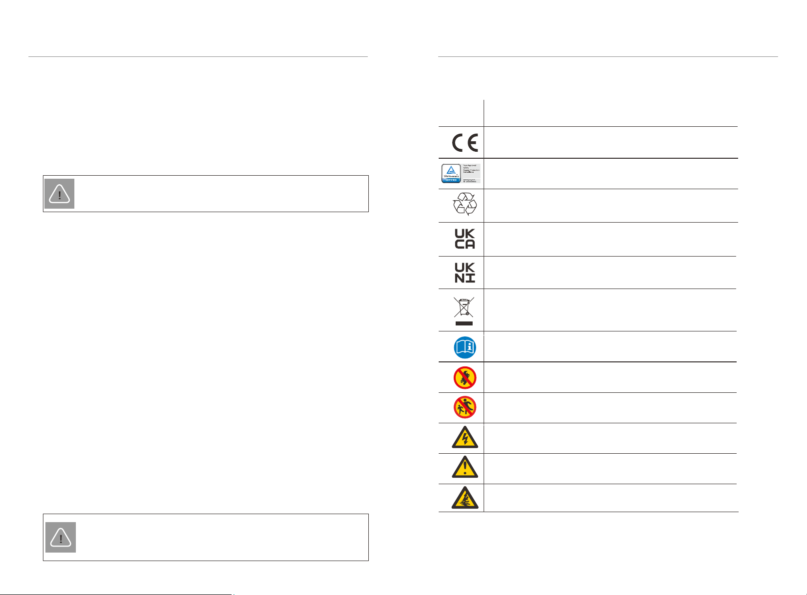
Symbol Explanation
Keep the battery system away from open flames or ignition
sources.
Keep the battery system away from children.
The battery module may explode.
The battery system must be disposed of at a proper facility
for environmentally-safe recycling.
CE mark of conformity
TUV certification
UKNI mark of conformity
UKCA mark of conformity
Do not dispose of the battery together with household
waste.
Caution, risk of electric shock
Caution, risk of danger
Read the enclosed documentation.
45
2.3 Qualified Installer
2. Safety 2. Safety
2.2 Response to Emergency Situations
2.2.1 Leaking Batteries
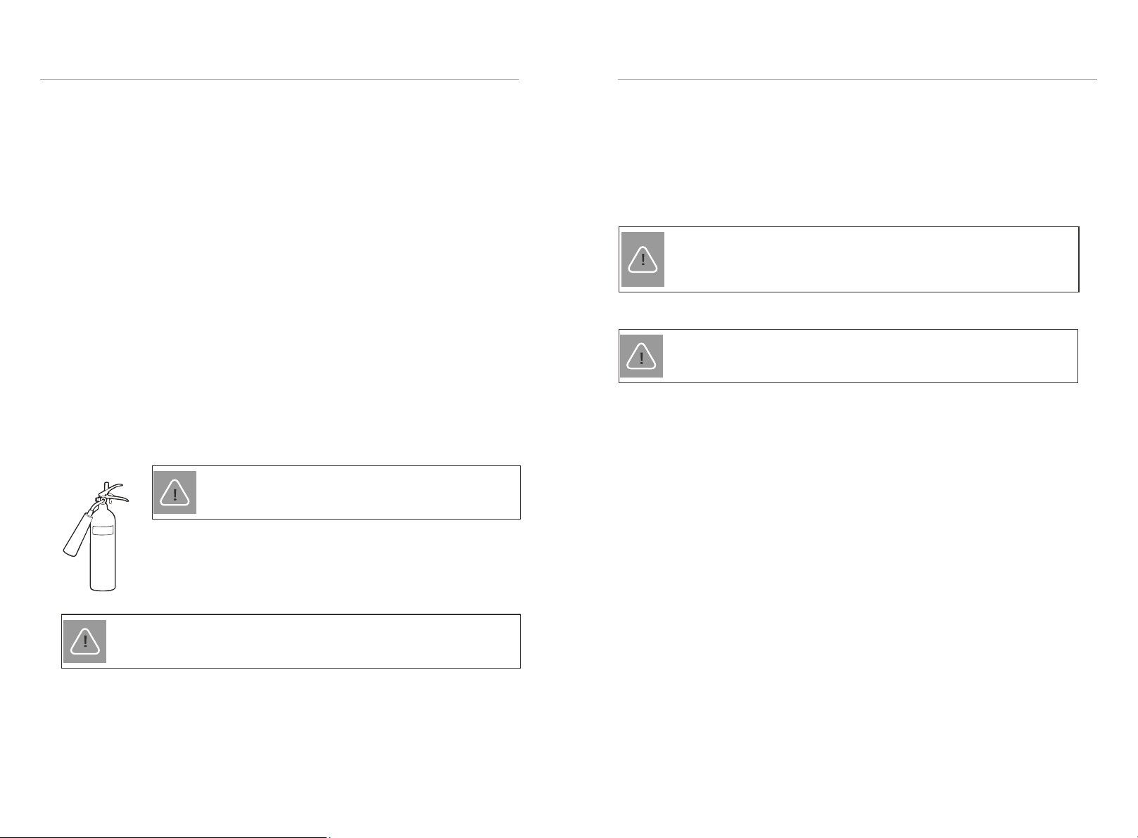
2.2.2 Fire
2.2.3 Wet Batteries and Damaged Batteries
Please keep a Class ABC fire extinguisher or a carbon dioxide extinguisher near the
equipment.
In case the leakage of electrolyte solution occurs, please avoid direct contact with
the electrolyte solution and the gas that may be generated by it. Direct contact may
lead to skin irritation or chemical burns. If the user comes into contact with the
electrolyte solution, please do as follows:
■Accidental inhalation of harmful substances:
Evacuate from the contaminated area, and seek medical attention immediately.
■Eye contact:
Rinse eyes with flowing water for 15 minutes, and seek medical attention
immediately.
■Dermal contact:
Wash the affected area thoroughly with soap and water, and seek medical
attention immediately.
■Ingestion:
Induce vomiting, and seek medical attention immediately.
Do not touch the battery module after being wet from and soaked in the water.
Do not use the battery module if it is damaged. Otherwise, the loss to life and
property will be caused.
Please pack the battery in its original packaging, and return it to our company or the
distributor.
CAUTION!
Damaged batteries may leak electrolyte or produce flammable gas. If a
user suspects that the battery is damaged, please immediately contact
our company for advice and information.
WARNING!
All operations of T-BAT-SYS-HV relating to electrical connection and
installation must be carried out by qualified personnel.
A skilled worker is defined as a trained and qualified electrician or installer who has
all of the following skills and experience:
■Knowledge of the functional principles and operation of grid-tied systems;
■Knowledge of the dangers and risks associated with installing and using
electrical devices and acceptable mitigation methods;
■Knowledge of the installation of electrical devices; and
■Knowledge of and adherence to this manual and all safety precautions and best
practices.
If a fire breaks out where the battery module is installed, please do
as follows:
1) Extinguish the fire before the battery module catches fire;
2) If the battery module cathes fire, please do not try to put out the
fire, and evacuate immediately.
WARNING!
The battery module may catch fire when heated above
302°F.
WARNING!
In case of catching fire, the battery module will produce noxious and
poisonous gases. Please keep away!
67
3 Product Introduction
3.1 Product Overview
3.1.1 Dimensions and Weight
3. Product Introduction
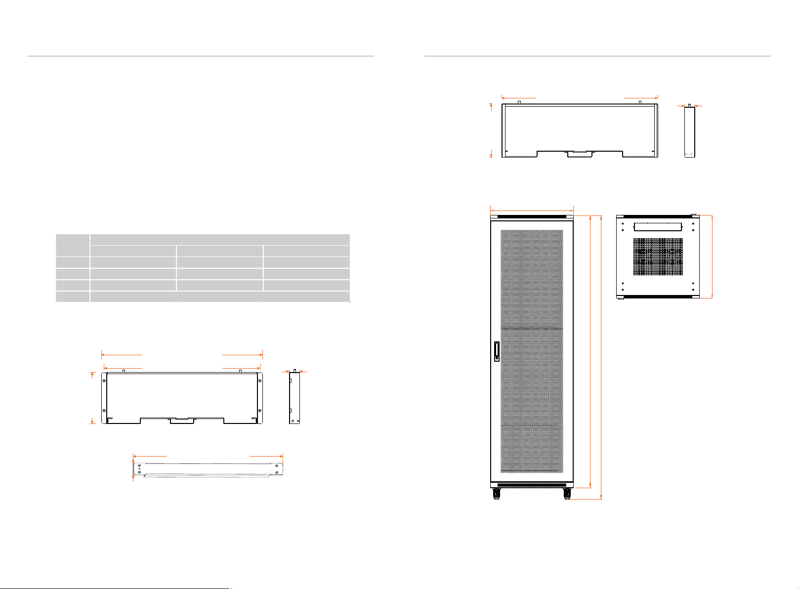
3.1.2 Installation Space
Base
Scheme A
Scheme B
Scheme C
11.81 in
300.00 mm
33.46 in
850.00 mm
5.83 in
148.00mm
1.02 in
26.00mm
2.95 in
75.00mm
33.46 in
850.00 mm 5.83 in
148.00mm
1.02 in
26.00mm
A battery management system (BMS) is an electronic system that manages a
rechargeable battery.
A battery module is a type of electrical battery which can be charged or
discharged into a load.
A battery system includes BMS, battery module(s) and a Rack (or Cabinet).
Cabinet
Rack
Front
18.94 in/481.00 mm
6.04 in
153.50 mm
18.30 in/465.00 mm
1.26 in
32.00 mm
Rear
17.65 in/448.40 mm
6.04 in
153.50 mm
1.26 in
32.00 mm
Metal Plate
15.26 in/387.50 mm
1.34 In
34.00 mm
3. Product Introduction
77.56 in/1970 mm
80.71 in/2050 mm
23.62 in/600 mm
23.62 in/600 mm
For safety reasons, installers are responsible for familiarizing themselves with the
contents of the Manual and all warnings before performing installation.
Front Support Rear Support Metal Plate
Length 18.94 in./481.00 mm 17.65 in./448.40 mm 15.26 in./387.50 mm
Width 1.26 in./32.00 mm 1.26 in./32.00 mm 1.34 in./34.00 mm
Height 6.04 in./153.50 mm 6.04 in./153.50 mm 0.31 in./8.00 mm
Weigth
3.97 lbs/1.8 kg
Rack
9
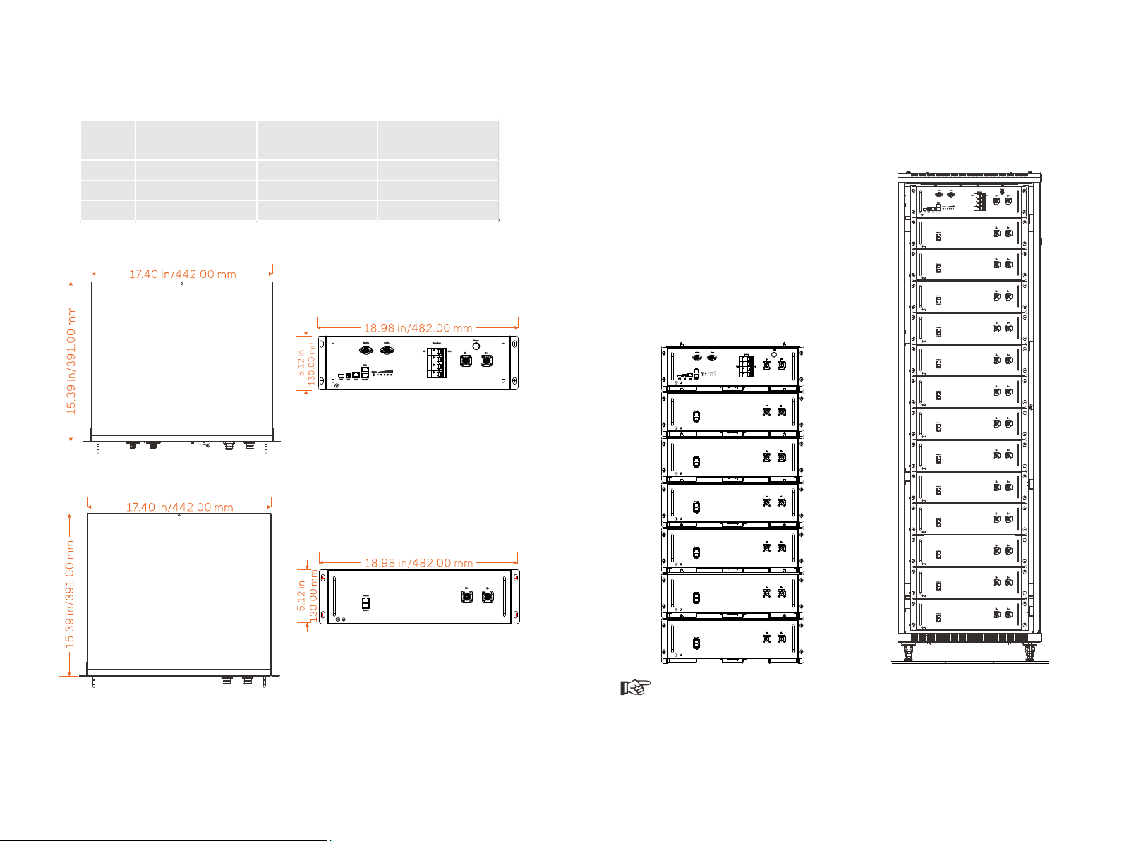
BMS (TBMS-MCR0800)
3. Product Introduction
3. Product Introduction
8
3.1.2 Installation Space
Note!
1) Currently, a Rack may withstand up to a BMS and 6 battery modules.
2) The above Cabinet is a standard cabinet, with both height and depth of 23.62
inches/600 mm. Users can purchase it based on their demands.
■Rack Installation ■Cabinet Installation
Battery Module (TP-HR25/TP-HR36)
TBMS-MCR0800 TP-HR25 TP-HR36
Length 17.40 in./442.00 mm 17.40 in./442.00 mm 17.40 in./442.00 mm
Width 15.39 in./391.00 mm 15.39 in./391.00 mm 15.39 in./391.00 mm
Height 5.12 in./130.00 mm 5.12 in./130.00 mm 5.12 in./130.00 mm
Weigth 17.64 lbs/8.00 kg 61.73 lbs/28.00 kg 68.34 lbs/31.00 kg
10 11
3.1.3 Appearance
■Section view of TBMS-MCR0800 i ii iii
iv v
■Section view of TP-HR25/TP-HR36
3. Product Introduction
3. Product Introduction
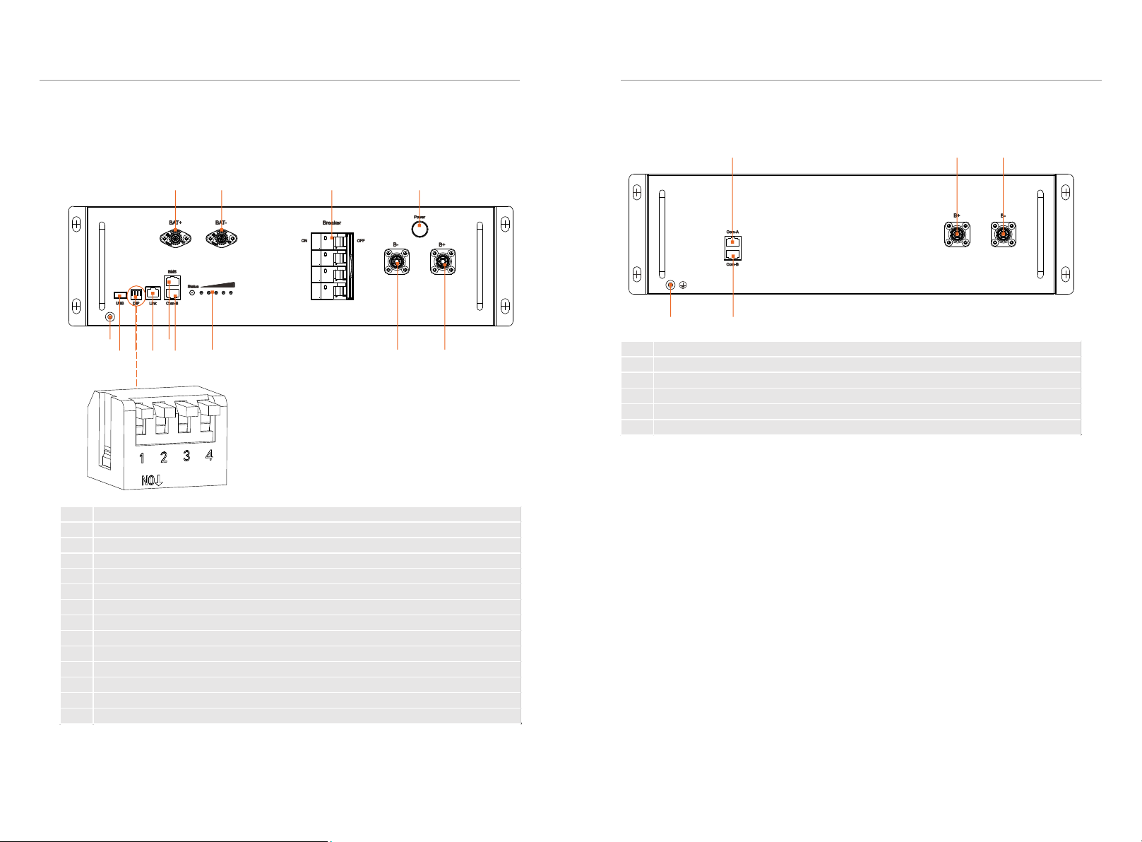
I II III IV
V IX
VI VII VIII X XI XII XIII
DIP switch 1: A reserved function
DIP switch 2: A reserved function
DIP switch 3: A reserved function
DIP switch 4: Terminal resistance
No. Description
I BAT+: Connect BMS's BAT+ to inverter's BAT+
II BAT-: Connect BMS's BAT - to inverter's BAT-
III Breaker: Input and output switch of battery module
IV Power Button: Open/close the battery system
V GND: BMS's GND
VI USB Port: A expansion function
VII DIP: Parallel operation of battery modules
VIII Link Port: Communication port for parallel operation of battery modules
IX BMS Port: Connect BMS's communication port and inverter's communication port
X COM-B: Connect battery module's COM A
XI Lamp Panel: Display real-time battery status
XII B-: Connect BMS‘s B- to battery module's B+
XIII B+: Connect BMS‘s B+ to battery module's B-
No. Description
i COM-A: Connect BMS's COM B or battery module's COM B
ii B+: Connect BMS's B- or battery module's B-
iii B-: Connect BMS's B+ or battery module's B+
iv GND: Battery module's GND
v COM-B: Connect battery module's COM A

12 13
3.2 Basic Features
3.2.1 Features
3.2.2 Certifications
3.3 Specifications
3.3.1 T-BAT-SYS-HV-R2.5
3. Product Introduction
3. Product Introduction
Continued on the next page
■Performance
The T-BAT-SYS-HV is one of the most advanced energy storage systems on the
market today, using state-of-the-art technology, and having the characteristics of
high reliability and convenient control. Characteristics are shown as follows:
■90% DOD;
■95% Battery Roundtrip Efficiency;
■Cycle Life > 6000 Cycles;
■Secondary Protection;
■IP20 Protection Level and Protection Class I;
■Safety & Reliability;
■Small Occupied Area;
■Floor Mounting.
■Configuration List
UN number UN 3480
Hazardous materials classification Class 9
UN transportation testing requirements UN 38.3
International protection marking IP20, Protection Class I
BAT system safety
CE, RCM, IEC 62619, IEC 62620,
IEC 62477-1, IEC 60730 Annex H,
IEC 62040, VDE-AR-E2510, IEC
60529, UN38.3
No. Module BMS Battery Module
Nominal
Energy (kWh)
Operating
Voltage (Vdc)
1 T-BAT H R5.0 TBMS-MCR0800 × 1 TP-HR25 × 2 5.12 90-116
2 T-BAT H R7.5 TBMS-MCR0800 × 1 TP-HR25 × 3 7.68 135-174
3 T-BAT H R10.0 TBMS-MCR0800 × 1 TP-HR25 × 4 10.24 180-232
4 T-BAT H R12.5 TBMS-MCR0800 × 1 TP-HR25 × 5 12.8 225-290
5 T-BAT H R15.0 TBMS-MCR0800 × 1 TP-HR25 × 6 15.36 270-349
6 T-BAT H R17.5 TBMS-MCR0800 × 1 TP-HR25 × 7 17.92 315-406
7 T-BAT H R20.0 TBMS-MCR0800 × 1 TP-HR25 × 8 20.48 360-465
8 T-BAT H R22.5 TBMS-MCR0800 × 1 TP-HR25 × 9 23.04 405-522
9 T-BAT H R25.0 TBMS-MCR0800 × 1 TP-HR25 × 10 25.6 450-580
10 T-BAT H R27.5 TBMS-MCR0800 × 1 TP-HR25 × 11 28.16 495-636
11 T-BAT H R30.0 TBMS-MCR0800 × 1 TP-HR25 × 12 30.72 540-695
12 T-BAT H R32.5 TBMS-MCR0800 × 1 TP-HR25 × 13 33.28 585-750
Module T-BAT H R5.0 T-BAT H R7.5 T-BAT H R10.0 T-BAT H R12.5 T-BAT H R15 T-BAT H R17.5
Nominal Voltage (Vdc) 102.4 153.6 204.8 256 307.2 358.4
Operating Voltage (Vdc) 90-116 135-174 180-232 225-290 270-349 315-406
Nominal Capacity (Ah) ①50 50 50 50 50 50
Nominal Energy (kWh) ①5.12 7.68 10.24 12.8 15.36 17.92
Usable Energy 90% DOD (kWh)
②
4.6 6.9 9.2 11.5 13.8 16.1
Max. Charge/Discharge Current
(A) ③
45 45 45 45 45 45
Recommend Charge/Discharge
Current (A) ⑤
30 30 30 30 30 30
Standard Power (kW) 2.56 3.84 5.12 6.4 7.68 8.96
Max. Power (kW) 4.6 6.9 9.2 11.5 13.8 16.1
Short-circuit Current (A) 2500 2500 2500 2500 2500 2500
Battery Roundtrip Effciency
(0.2C, 25°C/77°F)
Expected Lifetime (25°C/77°F)
Cycle Life 90% DOD (25°C/77°
F)
Charge Temperature
Discharge Temperature
Storage Temperature
Ingress Protection
Preotection Class
I
-4°F~122°F/-20°C~50°C (3 months)
50°F~104°F/10°C~40°C (1 year)
IP20
95%
10 Years
6000 Cycles
32°F~122°F/0°C~50°C ④
-4°F~122°F/-20°C~50°C ④

3. Product Introduction
Note:
①Test conditions: 100% DOD, 0.2C charge & discharge @+ 77°F/25°C.
②90% DOD; System usable energy may vary with inverter different setting.
③Discharge: In case of the battery cell's temperature range of -4°F~14°F/-
20°C~10°C and 113°F~122°F/45°C ~50°C, the discharge current will be reduced;
Charge: In case of the battery cell's temperature range of 32°F~77°F/0°C~25°C
and 113°F~122°F/45°C ~50°C, the charge current will be reduced. Product charge
or discharge power depends on the actual temperature of the battery pack.
④The battery can only be discharged and cannot be charged at -4°F~32°F/-
20°C~0°C.
⑤In case of a rated current of 30 A, the wire size of 10 AWG for ground wire is
recommended; in case of a rated current of 45 A, the wire size of 8 AWG for
ground wire is recommended. Note: The above-mentioned ground wires shall be
prepared by the user self.
⑥In the allowable range, the relative humidity range should be between 0% and
90% RH.
14 15
3. Product Introduction
3.3.2 T-BAT-SYS-HV-R3.6
Continued on the next page
■Performance
■Configuration List
Module T-BAT H R20 T-BAT H R22.5 T-BAT H R25 T-BAT H R27.5 T-BAT H R30 T-BAT H R32.5
Nominal Voltage (Vdc) 409.6 460.8 512 563.2 614.4 665.6
Operating Voltage (Vdc) 360-465 405-522 450-580 495-636 540-695 585-750
Nominal Capacity (Ah) ①50 50 50 50 50 50
Nominal Energy (kWh) ①20.48 23.04 25.6 28.16 30.72 33.28
Usable Energy 90% DOD (kWh) ②18.4 20.7 23.0 25.3 27.6 30
Max. Charge/Discharge Current
(A) ③
45 45 45 45 45 45
Recommend Charge/Discharge
Current (A) ⑤
30 30 30 30 30 30
Standard Power (kW) 10.24 11.52 12.8 14.08 15.36 16.64
Max. Power (kW) 18.4 20.7 23 25.3 27.6 30
Short-circuit Current (A) 2500 2500 2500 2500 2500 2500
Battery Roundtrip Effciency (0.2C,
25°C/77°F)
Expected Lifetime (25°C/77°F)
Cycle Life 90% DOD (25°C/77°F)
Charge Temperature
Discharge Temperature
Storage Temperature
Ingress Protection
Protection Class
I
-4°F~122°F/-20°C~50°C (3 months)
50°F~104°F/0°C~40°C (1 year)
IP20
95%
10 Years
6000 Cycles
32°F~122°F/0°C~50°C ④
-4°F~122°F/-20°C~50°C ④
No. Module BMS Battery Module
Nominal
Energy (kWh)
Operating
Voltage (Vdc)
1 T-BAT H R7.2 TBMS-MCR0800 × 1 TP-HR36 × 2 7.37 90-116
2 T-BAT H R10.8 TBMS-MCR0800 × 1 TP-HR36 × 3 11.06 135-174
3 T-BAT H R14.4 TBMS-MCR0800 × 1 TP-HR36 × 4 14.75 180-232
4 T-BAT H R18.0 TBMS-MCR0800 × 1 TP-HR36 × 5 18.43 225-290
5 T-BAT H R21.6 TBMS-MCR0800 × 1 TP-HR36 × 6 22.12 270-349
6 T-BAT H R25.2 TBMS-MCR0800 × 1 TP-HR36 × 7 25.8 315-406
7 T-BAT H R28.8 TBMS-MCR0800 × 1 TP-HR36 × 8 29.49 360-465
8 T-BAT H R32.4 TBMS-MCR0800 × 1 TP-HR36 × 9 33.18 405-522
9 T-BAT H R36 TBMS-MCR0800 × 1 TP-HR36 × 10 36.86 450-580
10 T-BAT H R39.6 TBMS-MCR0800 × 1 TP-HR36 × 11 40.55 495-636
11 T-BAT H R43.2 TBMS-MCR0800 × 1 TP-HR36 × 12 44.24 540-695
12 T-BAT H R46.8 TBMS-MCR0800 × 1 TP-HR36 × 13 47.92 585-750
Module T-BAT H R7.2 T-BAT H R10.8 T-BAT H R14.4 T-BAT H R18.0 T-BAT H R21.6 T-BAT H R25.2
Nominal Voltage (Vdc) 102.4 153.6 204.8 256 307.2 358.4
Operating Voltage (Vdc) 90-116 135-174 180-232 225-290 270-349 315-406
Nominal Capacity (Ah) ①72 72 72 72 72 72
Nominal Energy (kWh) ①5.12 7.68 10.24 12.8 15.36 17.92
Usable Energy 90% DOD (kWh)
②
6.6 10.0 13.3 16.6 19.9 23.2
Max. Charge/Discharge Current
(A) ③
50 50 50 50 50 50
Recommend Charge/Discharge
Current (A) ⑤
35 35 35 35 35 35
Standard Power (kW) 3.58 5.38 7.17 8.96 10.75 12.54
Max. Power (kW) 5.12 7.68 10.24 12.8 15.36 17.92
Short-circuit Current (A) 2500 2500 2500 2500 2500 2500
Battery Roundtrip Effciency
(0.2C, 25°C/77°F)
Expected Lifetime (25°C/77°F)
Cycle Life 90% DOD (25°C/77°
F)
Charge Temperature
Discharge Temperature
Storage Temperature
Ingress Protection
Protection Class
I
-4°F~122°F/-20°C~50°C (3 months)
50°F~104°F/10°C~40°C (1 year)
IP20
95%
10 Years
6000 Cycles
32°F~122°F/0°C~50°C ④
-4°F~122°F/-20°C~50°C ④

4. Preparation before Installation
4 Prepration before Installation
4.1 Prerequisites
NOTE!
If the ambient temperature exceeds the operating range, the battery
pack will stop running to protect itself. The optimal temperature range
for running is 59°F/15°C to 86°F/30°C. In the allowable range, the
relative humidity range should be between 0% and 90% RH.
Frequent exposure to harsh temperatures may deteriorate the
performance and lifetime of the battery.
3. Product Introduction
Note:
①Test conditions: 100% DOD, 0.2C charge & discharge @+ 77°F/25°C.
②90% DOD; System usable energy may vary with inverter different setting.
③Discharge: In case of the battery cell's temperature range of -4°F~14°F/-
20°C~10°C and 113°F~122°F/45°C ~50°C, the discharge current will be reduced;
Charge: In case of the battery cell's temperature range of 32°F~77°F/0°C~25°C
and 113°F~122°F/45°C ~50°C, the charge current will be reduced. Product charge
or discharge power depends on the actual temperature of the battery pack.
④The battery can only be discharged and cannot be charged at -4°F~32°F/-
20°C~0°C.
⑤In case of a rated current of 30 A, the wire size of 10 AWG for ground wire is
recommended; in case of a rated current of 50 A, the wire size of 8 AWG for
ground wire is recommended. Note: The above-mentioned ground wires shall be
prepared by the user self.
⑥In the allowable range, the relative humidity range should be between 0% and
90% RH.
16
When assembling the system, avoid touching the battery terminals with any metal
object or bare hands. According to the design principles, T-BAT-SYS-HV will
provide a safe and reliable energy. Improper operation and equipment damage may
cause overheating and electrolyte leakage. Therefore, the above-mentioned safety
precautions and warning information mentioned in this part shall be strictly
observed. If you have any question, please contact customer service. The “2
Safety” does not contain the provisions of all laws and regulations at the place
where the user located.
Before installation, make sure that the installation site meets the following
conditions:
■The building can stand up to earthquakes;
■The site shall be over 0.62 miles/997.79 m away from the sea, to avoid damage
caused by salt water and humidity;
■The floor shall be flat;
■No inflammable and explosive goods are placed within at least of 3 ft/0.91 m;
■The ambiance shall be shady and cool, away from heat sources and direct
sunlight;
■The temperature and humidity remain at a constant level;
■The installation site requires less dust and dirt; and
■There are no corrosive gases, including ammonia and acid vapor.
17
Module T-BAT H R28.8 T-BAT H R32.4 T-BAT H R36 T-BAT H R39.6 T-BAT H R43.2 T-BAT H R46.8
Nominal Voltage (Vdc) 409.6 460.8 512 563.2 614.4 665.6
Operating Voltage (Vdc) 360-465 405-522 450-580 495-636 540-695 585-750
Nominal Capacity (Ah) ①72 72 72 72 72 72
Nominal Energy (kWh) ①20.48 23.04 25.6 28.16 30.72 33.28
Usable Energy 90% DOD (kWh) ②26.5 29.9 33.2 36.5 39.8 43.1
Max. Charge/Discharge Current
(A) ③
50 50 50 50 50 50
Recommend Charge/Discharge
Current (A) ⑤
35 35 35 35 35 35
Standard Power (kW) 14.34 16.13 17.92 19.71 21.50 23.3
Max. Power (kW) 20.48 23.04 25.6 28.16 30.72 33.28
Short-circuit Current (A) 2500 2500 2500 2500 2500 2500
Battery Roundtrip Effciency (0.2C,
25°C/77°F)
Expected Lifetime (25°C/77°F)
Cycle Life 90% DOD (25°C/77°F)
Charge Temperature
Discharge Temperature
Storage Temperature
Ingress Protection
Protection Class
I
-4°F~122°F/-20°C~50°C (3 months)
50°F~104°F/10°C~40°C (1 year)
IP20
95%
10 Years
6000 Cycles
32°F~122°F/0°C~50°C ④
-4°F~122°F/-20°C~50°C ④
18 19
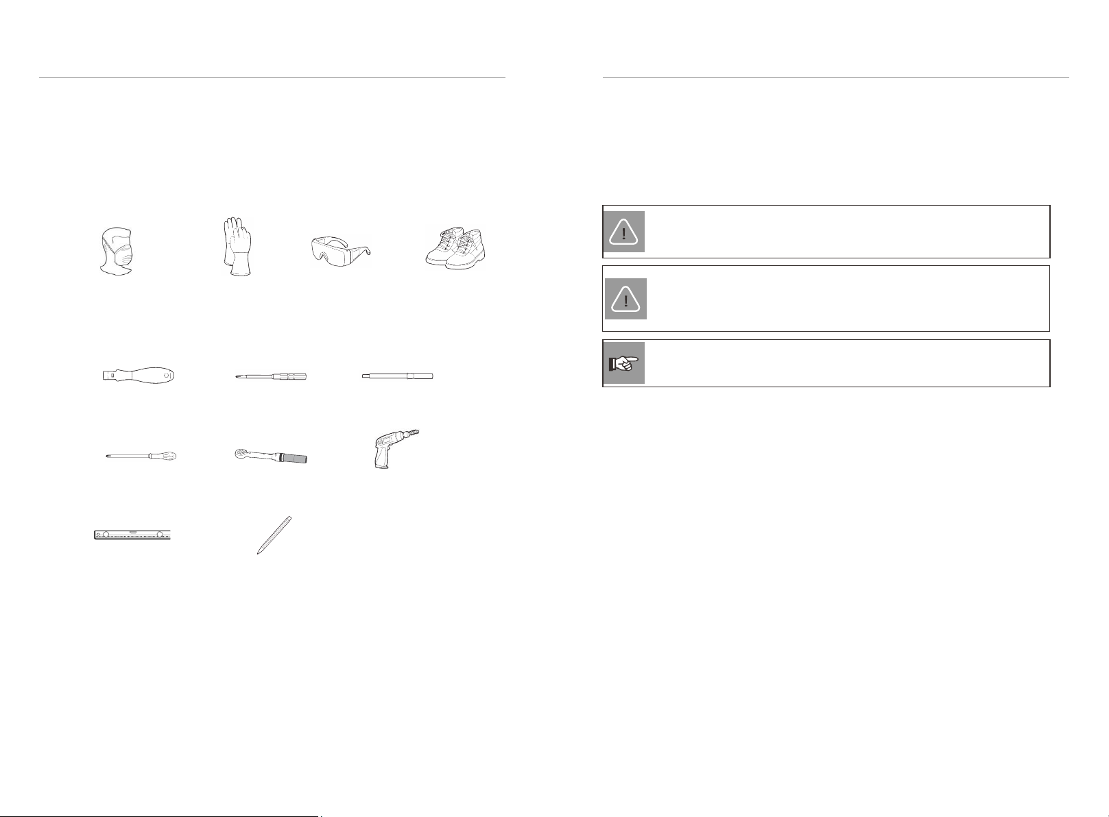
4.3 Tools
These tools are required to install the T-BAT system.
4.4 Preparation
4.4.1 Check for Transport Damage
4.2 Safety Gear
Installation and maintenance personnel must operate according to applicable
federal, state, and local regulations as well as industry standards regarding product
installation. Personnel must wear safety gear as indicated below in order to avoid
short circuit and personal injury.
Insulated Gloves Safety Goggles Safety Shoes
Anti-dust respirator
4.4.2 Unpacking
Unpack the battery package by removing the packing tape. Ensure the battery
modules and relevant items are complete. Refer to the packaging items in section
"4.4.3 Accessories" and check the packing lists carefully. If any accessory is
missing, immediately contact our company or your distributor directly.
WARNING!
Strictly follow the installation steps. Our company will not be
responsible for any injuries or loss incurred by incorrect assembly and
operation.
NOTE!
When installing the battery for the first time, the manufacturing date between
battery modules should not exceed 3 months.
4. Preparation before Installation 4. Preparation before Installation
Torque Screw Driver Phillips-screw Driver Hexagon Wrench
Pencil or Marker
Spirit Level
Torque Wrench Drill
Phillips-head Screw Driver
Ensure the battery is intact during and after transportation. If there are visible
damages such as cracks, contact your dealer immediately.
CAUTION!
According to regional regulations, several people may be required for
moving the equipment.
20 21
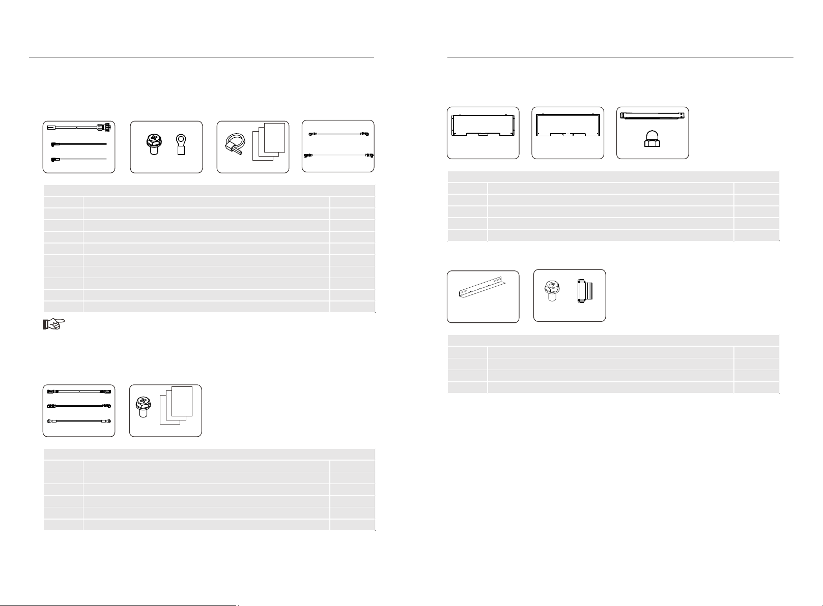
4.4.3 Accessories
■BMS (TBMS-MCR0800):
■One Battery Module (TP-HR25/TP-HR36 × 1):
The above components are only for one battery module. Our company will provide
corresponding components according to battery modules.
■Accessories for Quick Rack
A2 B2 D2
C2
■Accessories for Cabinet
A3 B3 C3
4. Preparation before Installation
4. Preparation before Installation
A1
B1
C1 D1 E1
The accessory with the “*” mark indicates that it will not be provided by our
company, and users can purchase from our company based on their own needs.
Note!
EF
A
B
CDG
H*
I*
Item Description Quantity
A
Communication Cable 1
B Power Cable (Black) 1
C Power Cable (Red) 1
D CrossExternalHexagon Screw (M6*L16) 4
E Ground Terminal 2
F Cable Tie (to ground cables together) 3
G Document 2
H* Power Cable (1.2 m for 2 to 6 battery modules)
I* Power Cable (2.2 m for 7 to 13 battery modules)
Accessories included are shown as follows:
Item Description Quantity
A1 Communication Cable 1
B1 Power Cable 1
C1 Ground Wire 1
D1 Cross Extermal Hexagon Screw (M6*L16) 4
E1 Document 1
Accessories included are shown as follows:
Item Description Quantity
A2 Front Side 1
B2 Rear Side 1
C2 Metal lPlate 1
D2 Cap Nut 4
Accessories included are shown as follows:
Item Description Quantity
A3 L-shaped Transverse Support 2
B3 CrossExternalHexagon Screw (M6*L16) 4
C3 Cassette Nut (M6) 8
Accessories included are shown as follows:

22 23
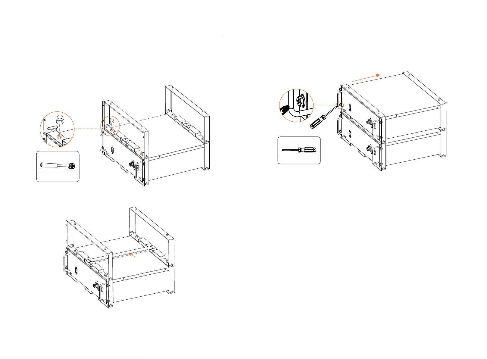
5. Equipment Installation
Regarding the Rack, users can purchase from our company. The following steps
take 6 battery modules as an example.
①
5. Equipment Installation 5. Equipment Installation
Step 2.
① Put the battery module into the rack
② Take the M6 × L16 screws (4 pcs) provided, and screw M6 × L16 into the front
side of the rack (Torque: 4-5 N·m)
M6 X L16 * 4
Torque: 4-5 N·m
Front side
Location hole
Location pin
Front
Rear side
Location pin
Location hole
Rear
②
Metal plate
Back side
Front side
Location hole
Location pin
Location hole
Location pin
5.1 Installation Environment Requirements
■Ensure that the equipment is installed in a well ventilated environment;
■To prevent fire due to high temperature, ensure that the ventilation vents or heat
dissipation system are not blocked when the equipment is running;
■Do not expose the equipment to flammable or explosive gas or smoke. Do not
perform any operation on the equipment in such environments;
■Ensure that the area is completely waterproof, and the floor is flat and level; and
■Ensure that the temperature and humidity is maintained at a constant level, and
there is minimal dust and dirt in the area.
5.2 Installation Mode
There are two alternative installation modes (rack and cabinet) available for users.
5.2.1 Rack Installation
■Installation Step
Step 1. Assemble rack
① Determine the front and rear sides, and place them on the floor
② Place the metal plate connecting both front and rear sides
5. Equipment Installation
24 25
5. Equipment Installation
Step 3. Add the rack and battery module
①Put the Front and Rear Sides, to make sure that location pins are securely
inserted into the location holes
②Screw both front and rear sides with Cap Nuts (4 pcs) (Torque: 4-6 N·m)
①Place the metal plate connecting both front and rear sides
Metal plate
①Put the battery module into the rack
②Screw M6×L16 into the front side of the second rack (Torque: 4-5 N·m)
M6 X L16 * 4
Torque: 4-5 N·m
Torque: 4-6 N·m
Cap Nut * 4

5. Equipment Installation 5. Equipment Installation
Step 5. Repeat the Step 4 to install the remaining battery modules and BMS
After installation is completed, it is shown as follows:
26 27
■Wiring
After installation, connect a battery module to another battery (or BMS), and BMS
to inverter.
•Battery module to battery module (or BMS)
Communication cable (1 pcs), power cable (1 pcs) and ground wire (1 pcs) are
provided in our packing list.
Power cable: there are two terminals with the same function at both ends; a power
cable in the packing list of battery module, one end connects to B+ of a battery
module, and the other connects to B- of the neighboring battery module (or B- of
BMS). A power cable in the packing list of BMS, one end connects B+ of BMS and
the other connects B- of a battery module at the bottom of the rack.
Ground wire: there are two terminals at both ends; one connects to a grounding
point of a battery module; and the other connects to grounding point of the
neighboring battery module or BMS.
Communication cable: there are two registered jacks at both ends; one connects to
Com-A of a battery module, and the other connects to Com-B of the neighboring
battery module (or COMM of BMS).
Caution!
There are two disassembly methods, with details as follows:
1. In case the entire device needs to be replaced, remove it from the top down,
including Rack;
2. In case one of the battery modules needs to be maintained, remove such a
battery module, reinstall it after finishing maintenance. If there is any other
battery that needs to be maintained, repeat the above-mentioned steps.
Caution!
Press and hold the “Lock Button” while unplugging the
power cable. Otherwise, it cannot be pulled out.
Lock Button

5. Equipment Installation 5. Equipment Installation
Connect cables between battery modules, and battery to BMS. See figure below.
Power Cable
Communication
Cable
Ground Wire
Warning!
The grounding wire must be connected.
28 29
•BMS to Inverter
Power cable (black): Connect BAT- of BMS to BAT– of inverter
Power cable (red): Connect BAT+ of BMS to BAT+ of inverter
The connector connecting to inverter from BMS is delivered with the inverter, for
details, please refer to the inverter's User Manual.
Note!
Communication cable: Connecting BMS's BMS and the inverter's BMS
Caution!
Press and hold the “Lock Button” while unplugging the
power cable. Otherwise, it cannot be pulled out.
Lock Button
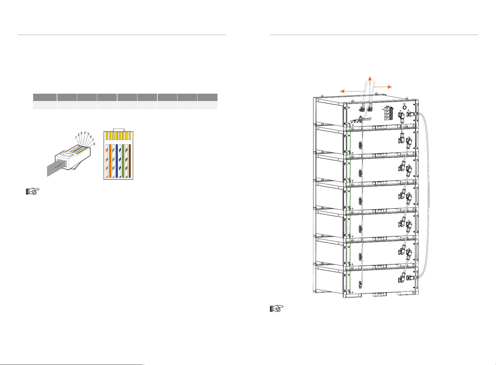
Sequence 1 2 3 4 5 6 7 8
BMS //BMS_H BMS_L /A1 B1
GND
■Making a BMS communication cable
If users want to make a BMS communication cable or a BMS communication cable
is required to be made before wiring, to ensure normal operation of BMS and
inverter, please read the following carefully.
The specific definition of the communication cable is shown as follows:
The wire order of the communication cable is as follows:
5. Equipment Installation 5. Equipment Installation
Connect cables between BMS and inverter. See figure below.
As users insert a power cable, the users should hear a click which indicates that the
cable connector is properly inserted into the port.
Note!
The BMS communication cable shall have a shield layer.
Note!
30 31
1 2 3456 7 8
1) Orange stripes on white
2) Orange
3) Green stripes on white
4) Blue
5) Blue stripes on white
6) Green
7) Brown stripes on white
8) Brown
Communication cable: connect BMS of BMS (battery
management system) to BMS of inverter
Power cable: connect BAT+ of
BMS to BAT+ of inverter
Power cable: connect BAT- of
BMS to BAT- of inverter
Note!
5. Equipment Installation 5. Equipment Installation
5.2.2 Cabinet Installation
As for the installation of outside cabinet, please follow the guide delivered with
the cabinet.
As for the installation of inside cabinet, please follow the steps as below.
There are two alternative sizes of cabinets available for users. The following
steps take 42U (1U = 4.445 cm) as an example.
Installation Step
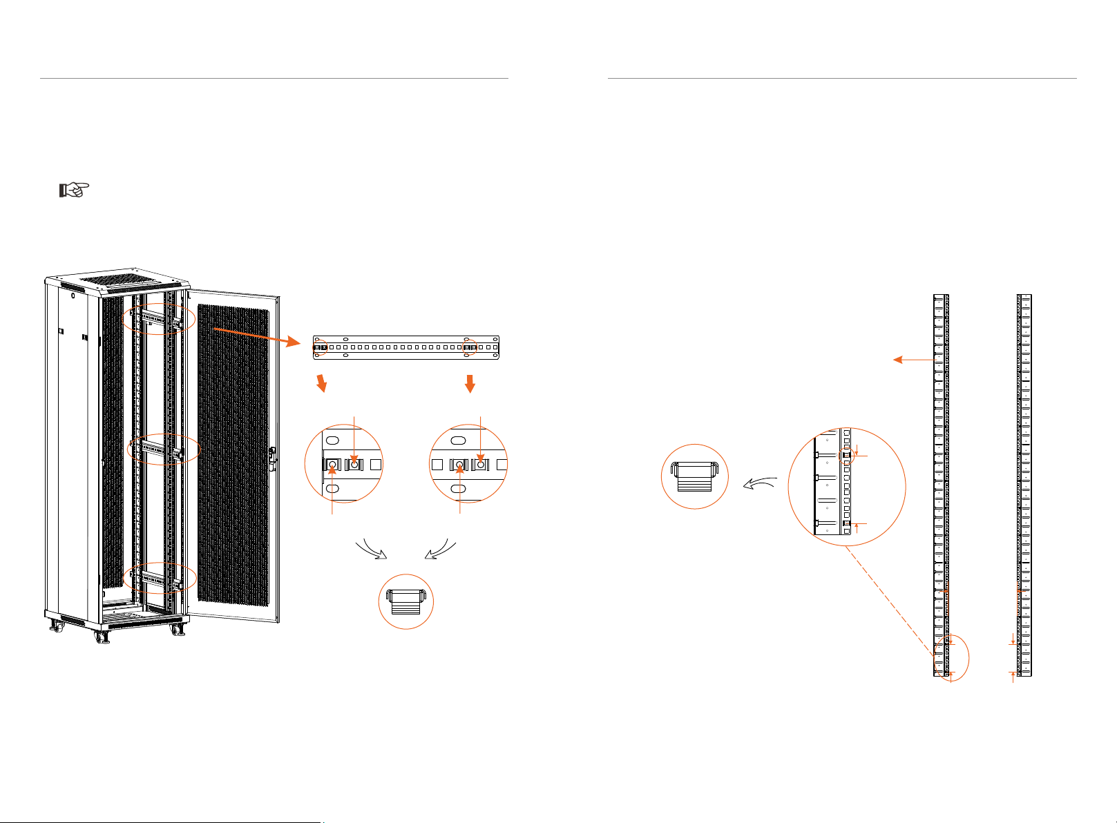
Step 1. Attach Mounting Rails into the cabinet. Make sure all four Mounting Rails
are at the same level. The distance between two Mounting Rails on one side shall
not be less than 15.75 in/400 mm.
32 33
5.2.2 Cabinet Installation
Note!
When installing outside cabinet, Cassette Nuts shall be inserted before installing
Fixed Rails, with 4 Cassette Nuts for one Fixed Rails. There are totaling 3 Fixed
Rails. See figure below.
As for the installation of inside cabinet and battery modules, please follow the steps
as below.
There are two alternative sizes (22U and 42U) of cabinets available for users. The
following steps take 42U (1U = 4.445 cm) with 13 battery modules as an example.
Second
First
Fourth
Fifth
Front sideRear side
As for the installation of outside cabinet, please follow the guide delivered with the
cabinet.
■Installation Step
Step 1. There are totaling 4 Mounting Rails. Insert Cassette Nuts into the holes on
the Mounting Rails every 3U (1U = 4.445 cm), with totaling 14 Cassette Nuts of one
Mounting Rail. See figure below. The distance between two Mounting Rails on one
side shall be at about 12.99 inches/330 mm.
Side View of Cabinet
3U
A distance at
about
12.99 inches
330 mm
3U
Front Rear
Note!
The four Mounting Rails are in the Package
C of NCB Network Cabinet.
(Cassette Nuts *14) x
(Mounting Rail * 4)
3U

5. Equipment Installation 5. Equipment Installation
Step 2. Insert Cassette Nuts into holes on the front Mounting Rail facing the cabinet
door, with totaling 28 Cassette Nuts of one front Mounting Rail.
①Insert the first Cassette Nut into a hole;
②Insert the second Cassette Nut 2U from the first;
③Insert the third Cassette Nut 1U from the second;
④Then repeat ② and ③.
Side View of Cabinet
34 35
Step 3. Fix and screw the L-shaped Transverse Support on the Mounting Rails with
Cross External Hexagon Screw (M6*L16 X 4) (Torque: 4-5 N·m). Make sure the two
Mounting Rails on one side are at the same level.
The two location holes on the L-shaped Transverse Support are long, please attach
the screws at the end of holes near mounting rail.
Note!
2U
1U
2U
Front
Rear
First Cassette Nut
Second Cassette Nut
Third Cassette Nut
Forth Cassette Nut
(Cassette Nuts * 28) x
(Mounting Rail (front) * 2)
2U
1U
2U
Front
Rear
M6 X L16 * 2
Torque: 4-5 N·m
This manual suits for next models
4
Table of contents
Other SolaX Power Batteries Pack manuals


