UPOWER Ecoline UE48LI100-3U User manual

Information Version: 1.0
48V100Ah LFP Product
Energy Storage
Lithium Battery Module
User Manual

1. Battery Panel Functions
48V100Ah - Energy Storage Lithium Battery Module - User Manual
This RS485 interface is used for battery
and inverter communication
Battery anode:
Connects to the positive pole of inverter
Negative battery:
Connects to the negative battery of the inverter
Address dip switch:
identifies addresses when batteries
are connected in parallel
The two 485 communication ports
use a communication connection
between the batteries
State
RUN light: green LED flashing to show the battery running status.
RUN
Alarm light: The red LED blinks to indicate that the battery is alarming, and the red LED blinks to indicate that the battery
is protected, as shown in the following table.
Alarm
OFF
Flash 1
Flash 1
Light
Light
Light
OFF
OFF
OFF
Flash 3
OFF
Flash 3
OFF
Light
02
Off to Sleep
No Charge and Discharge
Charging Mode
Battery Running Status ALMRUN
Dormancy
Normal
Warn
Normal
Warn
Overcharge Protection
Temperature or Current Protection
Paseo de Extremadura, 39 - 28935 Móstoles - Madrid (Spain)
Tel. +34 918 021 649 - Fax. +34 917 750 542
[email protected] - www.masterbattery.es/en

03
48V100Ah - Energy Storage Lithium Battery Module - User Manual
Discharge Mode
Normal
Warn
Low Voltage Protection
Temperature or Current Protection
Stop Charging
Stop Discharging
Stop Discharging
Flash 3
Flash 3
OFF
OFF
OFF
Flash 3
OFF
Light
State
Flash 1
Flash 2
Flash 3
Light
0.25S
0.5S
0.5S
OFF
3.75S
0.5S
1.5S
During battery installation or maintenance, you can determine the battery status based on the RUN and ALM displays.
This reset has the functions of manual wake up and start, manual shutdown and sleep, and reset. Users can flexibly use
it according to the actual situation. The specific operation methods are as follows:
1. Manual wake up function: When BMS is in hibernation state, press the button for 3 seconds and release it.
BMS will be activated and the battery will return to normal working mode
2. Manual sleep: When the battery is in the normal working state, press the button for 3 seconds and release the button.
The battery enters the low-power sleep state
3. Reset function: Press for more than 6 seconds to reset the battery when the battery is in normal working state.
Reset
It can communicate with the upper computer through RS232 interface and monitor various battery information through
the upper computer. The default baud rate is 9600 bps.
RS232
1 2 3 4 5 6
RS232 Port
Pin Number
Foot 1, 2, 6
Foot 3
Foot 4
Foot 5
Function Definition
NC
TX
RX
GND
Pin Definitions of the RS232 Port
Paseo de Extremadura, 39 - 28935 Móstoles - Madrid (Spain)
Tel. +34 918 021 649 - Fax. +34 917 750 542
[email protected] - www.masterbattery.es/en

04
48V100Ah - Energy Storage Lithium Battery Module - User Manual
RS485 terminal: (RJ45 port) the RS485 terminal outputs battery information. The default baud rate is 9600 bps. When
batteries are deployed in parallel, you need to set the address of each battery using a dip switch.
RS485
Pin Number
Foot 1 and Foot 8
Foot 2 and Foot 7
Foot 3 and Foot 6
Foot 4 and Foot 5
Function Definition
RS485-B
RS485-A
NC
NC
Pin Definitions of the RS485 Port
If battery strings are connected in parallel and need to communicate in cascading mode, the hardware address of each
battery must be configured. The hardware address can be set using the dip switch on the board. When the batteries are
in parallel, address 1 is the host and other addresses are slave.
The battery at address 1 is connected to the inverter; If the address is 0,
it is in single-battery mode
For details about the switch, see the following table.
ADD Switch
1 2 3 4
ON
OFF
Battery Address DefinitionAddress
Switch Position
1
OFF
ON
OFF
ON
OFF
ON
OFF
ON
OFF
ON
OFF
ON
OFF
ON
OFF
ON
3
OFF
OFF
OFF
OFF
ON
ON
ON
ON
OFF
OFF
OFF
OFF
ON
ON
ON
ON
4
OFF
OFF
OFF
OFF
OFF
OFF
OFF
OFF
ON
ON
ON
ON
ON
ON
ON
ON
PACK 0
PACK 1
PACK 2
PACK 3
PACK 4
PACK 5
PACK 6
PACK 7
PACK 8
PACK 9
PACK 10
PACK 11
PACK 12
PACK 13
PACK 14
PACK 15
0
1
2
3
4
5
6
7
8
9
10
11
12
13
14
15
2
OFF
OFF
ON
ON
OFF
OFF
ON
ON
OFF
OFF
ON
ON
OFF
OFF
ON
ON
Paseo de Extremadura, 39 - 28935 Móstoles - Madrid (Spain)
Tel. +34 918 021 649 - Fax. +34 917 750 542
[email protected] - www.masterbattery.es/en

Inverter design
Note:
When multiple batteries
are connected in parallel,
the battery at address 1
communicates with the
inverter, and the order
battery addresses are
coded from address 2
05
48V100Ah - Energy Storage Lithium Battery Module - User Manual
Schematic diagram of battery parallel installation
Note: The battery should be turned off during installation. After installation, check OK and then turn on the battery.
Paseo de Extremadura, 39 - 28935 Móstoles - Madrid (Spain)
Tel. +34 918 021 649 - Fax. +34 917 750 542
[email protected] - www.masterbattery.es/en

06
48V100Ah - Energy Storage Lithium Battery Module - User Manual
2. Installation Tools
Attention before installation:
2.1 Insulation tools should be used to prevent short circuit during installation.
2.2 Power terminal installation must be checked for tightening, whether there is rust, corrosion or other foreign bodies,
if there should be wipe Clean, tighten the bolt, the battery bolt virtual connection will lead to the connection voltage
drop is too large, even when the current is large The heat burned the battery.
Following tools are required to install the battery module
NOTE:Use properly insulated tools to prevent accidental electric shock or short circuits. If insulated tools are not
available, cover the entire exposed metal surfaces of the available tools, except their tips, with electrical tape.
When installing batteries, strictly follow the following steps. Do not change the installation sequence at will:
3.1 Before installing the battery, ensure that the battery is powered off or hibernated,If the battery is turned on or woke
up, press the "REST" button on the battery panel. Hold down the button for 3 seconds before releasing it. At this
time, the battery will enter the hibernation state, and the battery has no voltage output.
Electric Tools Wire Cutter Crimping Modular Plier
3. Installation Steps
Paseo de Extremadura, 39 - 28935 Móstoles - Madrid (Spain)
Tel. +34 918 021 649 - Fax. +34 917 750 542
[email protected] - www.masterbattery.es/en

07
48V100Ah - Energy Storage Lithium Battery Module - User Manual
3.2 Place the batteries to be installed into the rack one by one, and install the screws that secure the batteries to the
rack.
3.3 Connect the negative wires: After the battery is fixed, connect all the negative terminals of the battery together, and
finally connect the negative terminal of the inverter DC input to the negative terminal of the battery.
3.4 Connect the positive wires: Connect all the positive terminals of the battery. Finally, connect the positive terminal of
the inverter dc input to the positive terminal of the battery.
3.5 Connect the parallel communication lines: See the figure below.
Use this cable to connect the
communication connection
between the batteries
Paseo de Extremadura, 39 - 28935 Móstoles - Madrid (Spain)
Tel. +34 918 021 649 - Fax. +34 917 750 542
[email protected] - www.masterbattery.es/en

08
48V100Ah - Energy Storage Lithium Battery Module - User Manual
3.6 Connect the communication cable between the battery and the inverter:
This end connects to the
Remote Box of the inverter
This port connects to the
RS485 port of the battery
Note: This communication line should be
connected with attention to the direction
Paseo de Extremadura, 39 - 28935 Móstoles - Madrid (Spain)
Tel. +34 918 021 649 - Fax. +34 917 750 542
[email protected] - www.masterbattery.es/en

09
48V100Ah - Energy Storage Lithium Battery Module - User Manual
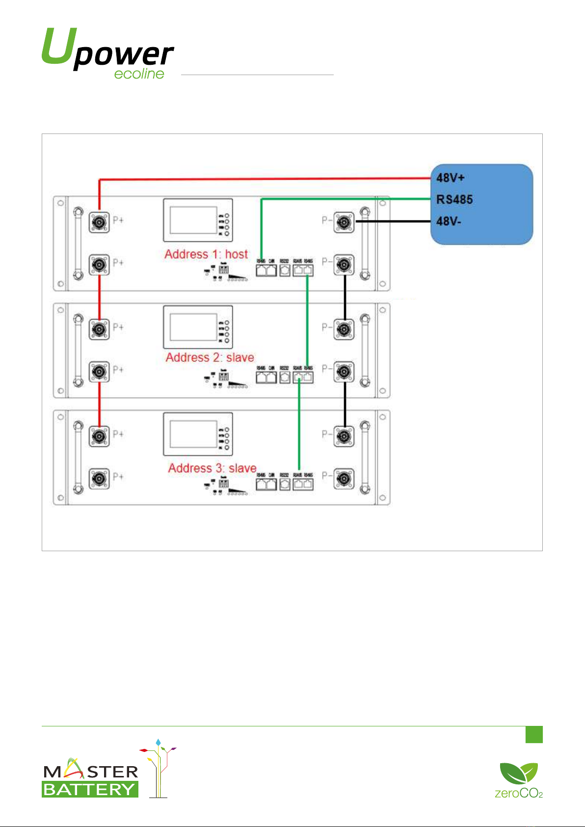
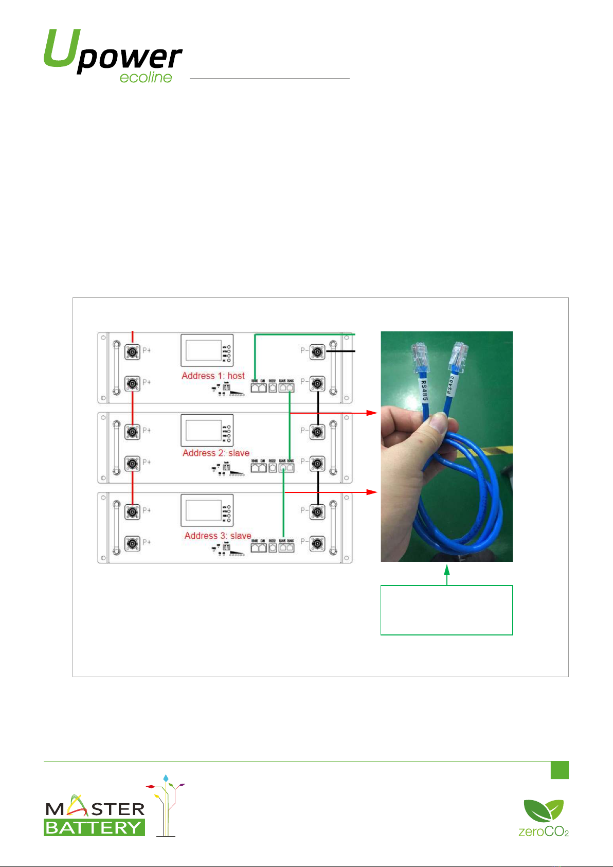
3.7 Setting the Battery Address: After the preceding operations are complete, set the IP address of the battery
connected to the inverter to 1, and set other IP addresses from 2 until all the Settings are complete.
Note: The address of the battery must not be the same. Otherwise, communication will be affected.
3.8 Check that all connections are correct and firm.
3.9 Start the inverter to charge the battery. In normal state, all the batteries will be activated and enter the working
mode.
4.1 Preliminary determination steps:
The battery can be turned on, but red light is lighting, and cannot charge or discharge. If the red light is lighting, that
means system is abnormal, please check values as following:
Temperature: Above 55ºC or under -20ºC, the battery could not work.
Solution: to move battery to the normal operating temperature range between -20ºC and 55ºC.
Current: If current is greater than 110A, battery protection will turn on.
Solution: Check whether current is too large or not, if it is, to change the settings on power supply side.
High Voltage: If charging voltage above 54V, battery protection will turn on.
Solution: Check whether voltage is too high or not, if it is, to change the settings on power supply side.
Low Voltage: When the battery discharges to 44.5V or less, battery protection will turn on.
Solution: Charge the battery for some time, the red light turn off. Excluding the four points above, if the faulty is still
cannot be located, turn off power switch of the battery and repair.
4.2 The battery cannot be charged or discharged.
4.2.1 No charging: First check that the charging voltage of the charging device is normal, if the charging voltage is
normal (52.5V-54.75)V), and then use the upper computer to connect with the battery, read the detailed data of the
battery, check whether the voltage and temperature of the single battery are normal, if the charging equipment is
normal, the general reason for not charging is: the single charging over voltage protection or high temperature
protection.
4.2.2 Fail to discharge: Disconnect the battery from the load and measure whether the voltage of the battery is
normal, If the battery has no output voltage, press the Reset button to sleep the battery first and then wake up
(restart the battery), and test the battery voltage again. If the battery voltage returns to normal, it indicates that the
battery is protected, Check the load.
4. Trouble Shooting Steps
Paseo de Extremadura, 39 - 28935 Móstoles - Madrid (Spain)
Tel. +34 918 021 649 - Fax. +34 917 750 542
[email protected] - www.masterbattery.es/en

10
48V100Ah - Energy Storage Lithium Battery Module - User Manual
If there is no voltage output after the battery is restarted, connect the battery to the host computer and check
whether the battery voltage and temperature are normal.
Generally cannot discharge the reason is: temperature protection, over current protection, under voltage protection.
5.1 Leaking Batteries If the battery module leaks electrolyte, avoid contact with the leaking liquid or gas.
If one is exposed to the leaked substance, immediately perform the actions described below:
• Evacuate the contaminated area, and seek medical attention.
• If the body comes into contact with harmful substances such as electrolytes, wash it thoroughly with soap and
water immediately. If you feel unwell, seek medical attention immediately.
5.2 If smoke or open flame is found in the battery, use only a dry powder extinguisher. If possible, the battery should be
removed and placed in a safe place before the battery module catches fire to avoid greater damage.
5.3 Damaged batteries are dangerous and must be handled with great care. If faulty batteries need to be stored, store
them in a special warehouse and take fire control measures.
5.4 If the electrolyte of the battery is found to leak, then the battery needs to be scrapped, contact a professional battery
recycling company in your area.
5. Emergency Measures
Paseo de Extremadura, 39 - 28935 Móstoles - Madrid (Spain)
Tel. +34 918 021 649 - Fax. +34 917 750 542
[email protected] - www.masterbattery.es/en
Table of contents
Other UPOWER Ecoline Batteries Pack manuals

UPOWER Ecoline
UPOWER Ecoline NauticBattery NA-12LI22BL User manual

UPOWER Ecoline
UPOWER Ecoline NauticBattery NA-12Li50BL User manual

UPOWER Ecoline
UPOWER Ecoline UE-24Li10BL User manual

UPOWER Ecoline
UPOWER Ecoline NauticBattery NA-12Li125BL User manual

UPOWER Ecoline
UPOWER Ecoline NauticBattery NA-12Li100BL User manual

UPOWER Ecoline
UPOWER Ecoline NauticBattery NA-12Li200BL User manual

UPOWER Ecoline
UPOWER Ecoline UE-48Li50BL User manual

UPOWER Ecoline
UPOWER Ecoline NauticBattery NA-12Li300BL User manual

UPOWER Ecoline
UPOWER Ecoline UE-48LI3750I User manual

UPOWER Ecoline
UPOWER Ecoline UE-I Series User manual