Urban Air UFM - 13 LAMBADA Technical specifications

Operations and Flight Manual
UFM – 13 LAMBADA
Serial No. 105/13
Date of Issue: 30/01/2008
Urban Air s.r.o., T.G.Masaryka 897, 562 01 Ústí nad Orlicí, Czech Republic,
Tel./fax: +420 465 582 573, E-mail: urbanair@urbanair.cz


F
FL
LI
IG
GH
HT
T
M
MA
AN
NU
UA
AL
L
F
FO
OR
R
U
UL
LT
TR
RA
AL
LI
IG
GH
HT
T
A
AE
ER
RO
OP
PL
LA
AN
NE
E
U
UF
FM
M
–
–
1
13
3
Date of Issue: 30. 1. 2008
0-1
0. Table of Contents
0. Table of Contents...................................................................0-11
1. General......................................................................................1-0
2. Limitations................................................................................2-0
3. Emegency procedures...........................................................3-0
4. Normal procedures..................................................................4-0
5. Performance.............................................................................5-0
6. Weight and Balance.................................................................6-0
7. Aeroplane and Systems Description .....................................7-3
8. Aeroplane handling, servicing and maintenance...............8-13
9. Supplements.............................................................................9-0

F
FL
LI
IG
GH
HT
T
M
MA
AN
NU
UA
AL
L
F
FO
OR
R
U
UL
LT
TR
RA
AL
LI
IG
GH
HT
T
A
AE
ER
RO
OP
PL
LA
AN
NE
E
U
UF
FM
M
–
–
1
13
3
Date of Issue: 30. 1. 2008
1-0
Section 1
1. General
1.1 Introduction..................................................................................1-1
1.2 Certification basis........................................................................1-1
1.3 Warnings, cautions and notes.....................................................1-3
1.4 Descriptive data...........................................................................1-4
1.5 Three-view drawing.....................................................................1-7

F
FL
LI
IG
GH
HT
T
M
MA
AN
NU
UA
AL
L
F
FO
OR
R
U
UL
LT
TR
RA
AL
LI
IG
GH
HT
T
A
AE
ER
RO
OP
PL
LA
AN
NE
E
U
UF
FM
M
–
–
1
13
3
Date of Issue: 30. 1. 2008
1-1
1.1 Introduction
This Flight Manual provides information useful for the safe and effi-
cient operation of UFM - 13 ultralight aeroplane.
It also contains supplemental data supplied by the aeroplane
manufacturer.
1.2 Certification basis
This type of aeroplane has been designed in compliance with
„Požadavky na letovou způsobilost Sportovních létajících zařízení
Ultralehké letouny řízené aerodynamicky UL-2 část I (Ultralight Airwor-
thiness Requirements UL-2, part I)“, that is the valid Certification basis for
the ULTRALIGHT category aeroplanes approved by the Czech Amateur
Light Aircraft Association (www.laacr.cz ).

F
FL
LI
IG
GH
HT
T
M
MA
AN
NU
UA
AL
L
F
FO
OR
R
U
UL
LT
TR
RA
AL
LI
IG
GH
HT
T
A
AE
ER
RO
OP
PL
LA
AN
NE
E
U
UF
FM
M
–
–
1
13
3
Date of Issue: 30. 1. 2008
1-2

F
FL
LI
IG
GH
HT
T
M
MA
AN
NU
UA
AL
L
F
FO
OR
R
U
UL
LT
TR
RA
AL
LI
IG
GH
HT
T
A
AE
ER
RO
OP
PL
LA
AN
NE
E
U
UF
FM
M
–
–
1
13
3
Date of Issue: 30. 1. 2008
1-3
1.3 Warnings, cautions and notes
The following definitions apply to warnings, cautions and notes in
the flight manual.
Warning
Means that the non-observation of the corresponding proce-
dure leads to an immediate or important degradation of the flight
safety.
Caution
Means that the non-observation of the corresponding proce-
dure leads to a minor or to a more or less long term degradation of the
flight safety.
Note
Draws the attention of any special item not directly related to
safety but which is important or unusual.

F
FL
LI
IG
GH
HT
T
M
MA
AN
NU
UA
AL
L
F
FO
OR
R
U
UL
LT
TR
RA
AL
LI
IG
GH
HT
T
A
AE
ER
RO
OP
PL
LA
AN
NE
E
U
UF
FM
M
–
–
1
13
3
Date of Issue: 30. 1. 2008
1-4
1.4 Descriptive data
1.4.1 Aeroplane description
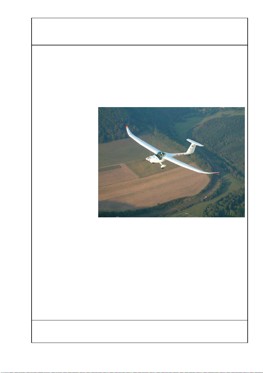
UFM - 13 ultralight aeroplane is intended for recreational and
cross-country flying. It is not approved for aerobatic operation.
UFM - 13 is
a single engine, all-
fibreglass aeroplane
with two side-by-
side seats. The
aeroplane is
equipped with fixed
two main wheel
undercarriage with a
steer able tail wheel.
The fuselage is a
fibreglass shell with
fibreglass seats
integrated. Safety
belts are attached to
the seats and to a
shelf intended for
putting off lightweight objects (headphones, maps, etc.).
The wing is a monospar construction with a sandwich skin com-
posed of two layers of fibreglass and special foam. Control surfaces and
empennage is of the same construction.
The aeroplane is controlled by dual push-pull control system, only
rudder drive is controlled by cable. The ailerons and elevator are controlled
by the control stick located between the pilot's legs (co-pilot's). The rudder
is controlled by the rudder pedals, flaps are operated by a control lever
located between the pilots on the fuselage main spar.

F
FL
LI
IG
GH
HT
T
M
MA
AN
NU
UA
AL
L
F
FO
OR
R
U
UL
LT
TR
RA
AL
LI
IG
GH
HT
T
A
AE
ER
RO
OP
PL
LA
AN
NE
E
U
UF
FM
M
–
–
1
13
3
Date of Issue: 30. 1. 2008
1-5
1.4.2 Basic Technical data
Wing
Span/span with wing extension ........................ 12.94/14.95m
Area/area with wing extension.......................... 12.16/12.87m
2
MAC.................................................................... 0.987m
Loading/loading area with wing extension....... 37/34.9kg/m
2
Flaperon
area..................................................................... 0.82 m
2
Fuselage
length .................................................................. 6.6 m
width.................................................................... 1.08 m
height .................................................................. 1.95 m
Horizontal tail unit
span .................................................................... 2.5 m
area..................................................................... 1.3 m
2
elevator area....................................................... 0.45 m
2

F
FL
LI
IG
GH
HT
T
M
MA
AN
NU
UA
AL
L
F
FO
OR
R
U
UL
LT
TR
RA
AL
LI
IG
GH
HT
T
A
AE
ER
RO
OP
PL
LA
AN
NE
E
U
UF
FM
M
–
–
1
13
3
Date of Issue: 30. 1. 2008
1-6
Vertical tail unit
height .................................................................. 1.2 m
area..................................................................... 1.1 m
2
rudder area ......................................................... 0.44 m
2
Landing gear
wheel track.......................................................... 1.54 m
wheel base.......................................................... 4.16 m
main wheel diameter........................................... 0.4 m
tail wheel diameter.............................................. 0.2 m

F
FL
LI
IG
GH
HT
T
M
MA
AN
NU
UA
AL
L
F
FO
OR
R
U
UL
LT
TR
RA
AL
LI
IG
GH
HT
T
A
AE
ER
RO
OP
PL
LA
AN
NE
E
U
UF
FM
M
–
–
1
13
3
Date of Issue: 30. 1. 2008
1-7
1.5 Three-view drawing

F
FL
LI
IG
GH
HT
T
M
MA
AN
NU
UA
AL
L
F
FO
OR
R
U
UL
LT
TR
RA
AL
LI
IG
GH
HT
T
A
AE
ER
RO
OP
PL
LA
AN
NE
E
U
UF
FM
M
–
–
1
13
3
Date of Issue: 30. 1. 2008
2-0
Section 2
2. Limitations
2.1 Introduction..................................................................................2-1
2.2 Airspeed......................................................................................2-1
2.3 Airspeed indicator markings........................................................2-2
2.4 Powerplant ..................................................................................2-3
2.5 Powerplant instrument markings.................................................2-5
2.6 Miscellaneous instrument markings............................................2-6
2.7 Weight.........................................................................................2-7
2.8 Centre of gravity..........................................................................2-7
2.9 Approved manoeuvres................................................................2-7
2.10 Manoeuvring load factors............................................................2-8
2.11 Crew............................................................................................2-9
2.12 Kinds of operation .......................................................................2-9
2.13 Fuel............................................................................................2-10
2.14 Maximum passenger seating....................................................2-10
2.15 Other limitations ........................................................................2-11
2.16 Limitation placards ....................................................................2-12

F
FL
LI
IG
GH
HT
T
M
MA
AN
NU
UA
AL
L
F
FO
OR
R
U
UL
LT
TR
RA
AL
LI
IG
GH
HT
T
A
AE
ER
RO
OP
PL
LA
AN
NE
E
U
UF
FM
M
–
–
1
13
3
Date of Issue: 30. 1. 2008
2-1
2.1 Introduction
Section 2 includes Operating limitations, instrument markings, and
basic placards necessary for safe operation of the aeroplane, its engine,
standard systems and standard equipment.
2.2 Airspeed
Airspeed limitations and their operational significance are shown
below:
Airspeed IAS
[km/h] Remarks
V
NE
Never exceed
speed 200 Do not exceed this speed in
any operation.
V
NO
Maximum
structural
cruising speed 145 Do not exceed this speed
except in smooth air, and
then only with caution.
V
A
Manoeuvring
speed 135
Do not make full or abrupt
control movement above
this speed, because under
certain conditions the air-
craft may be overstressed
by full control movement.
V
FE
Maximum Flap.
Extension speed 110 Do not exceed this speed
with flaps extended

F
FL
LI
IG
GH
HT
T
M
MA
AN
NU
UA
AL
L
F
FO
OR
R
U
UL
LT
TR
RA
AL
LI
IG
GH
HT
T
A
AE
ER
RO
OP
PL
LA
AN
NE
E
U
UF
FM
M
–
–
1
13
3
Date of Issue: 30. 1. 2008
2-2
2.3 Airspeed indicator markings
Airspeed indicator markings and their colour-code significance are
shown below:
Marking Range or value
[IAS km/h] Significance
White
arc 70 - 110 Positive Flap Operating Range
Green
arc 80 – 145 Normal Operating Range
Yellow
arc 145 – 200 Manoeuvres must be con-
ducted with caution and only in
smooth air.
Red
line 200 Maximum speed for all opera-
tions.

F
FL
LI
IG
GH
HT
T
M
MA
AN
NU
UA
AL
L
F
FO
OR
R
U
UL
LT
TR
RA
AL
LI
IG
GH
HT
T
A
AE
ER
RO
OP
PL
LA
AN
NE
E
U
UF
FM
M
–
–
1
13
3
Date of Issue: 30. 1. 2008
2-3
2.4 Powerplant
Engine Manufacturer :Bombardier-Rotax GMBH
Engine Model: Rotax 912 UL
Power:
Max. Take-off: 59,6 kW / 80 hp
Max. Continuous: 58 kW / 78 hp
at 5500 rpm
Cruising: 53 kW / 71 hp
at 4800 rpm
Engine RPM:
Max. Take-off: 5800 rpm, max. 5 min.
Max. Continuous: 5500 rpm
Cruising: 4800 rpm
Idling: 1400 rpm
Cylinder head temperature:
Minimum: 60 °C
Maximum: 150 °C
Oil temperature:
Minimum: 50 °C
Maximum: 140 °C
Opt. operating: 90 °C – 100 °C

F
FL
LI
IG
GH
HT
T
M
MA
AN
NU
UA
AL
L
F
FO
OR
R
U
UL
LT
TR
RA
AL
LI
IG
GH
HT
T
A
AE
ER
RO
OP
PL
LA
AN
NE
E
U
UF
FM
M
–
–
1
13
3
Date of Issue: 30. 1. 2008
2-4
Fuel pressure (if the fuel gauge and sensor are installed):
Minimum: 0.40 bar
Maximum: 0.15 bar
Fuel: see 2.13
Oil: Automotive engine oil of registered brand
with
gear additives, but not aircraft oil (refer to
engine Operator’s Manual).
API classification „SF“ or „SG“.
Propeller: VARIA 160/2/R
Propeller diameter: 1600 mm
Warning
The Rotax 912 UL has not been certified as an aircraft engine
and its failure may occur at any time. The pilot is fully responsi-
ble for consequences of such a failure.

F
FL
LI
IG
GH
HT
T
M
MA
AN
NU
UA
AL
L
F
FO
OR
R
U
UL
LT
TR
RA
AL
LI
IG
GH
HT
T
A
AE
ER
RO
OP
PL
LA
AN
NE
E
U
UF
FM
M
–
–
1
13
3
Date of Issue: 30. 1. 2008
2-5
2.5 Powerplant instrument markings
Function Minimum
Limit Normal
Operating
Range
Caution
Range Maximum
Range
Engine
speed
(RPM) 1400 1400-5500 5500-5800 5800
Cylinder
Head
Temperature
(CHT)
[°C]
60 60-100 100-150 150
Oil
Temperature
[°C] 50 90-110 110-140 140
Oil
Pressure
[bar] 1.5 1.5 – 4.0 4.0 – 5.0 7.0 cold
engine
starting
Note
In the TL engine instrument memory are stored the limits of 1
st
and
2
nd
level for Rotax 912 engine. The values of limits are stated in Op-
erator’s Manual for the TL engine instrument. A limit overrun is indi-
cated by indicating lamp flashing and stored in the TL engine instru-
ment memory for further evaluation. Make note of these limits and
do not exceed them. If the limits are exceeded and a message
„SERVICE“ is shown on the TL engine instrument display - contact
engine manufacturer or Rotax Service Centre for help.

F
FL
LI
IG
GH
HT
T
M
MA
AN
NU
UA
AL
L
F
FO
OR
R
U
UL
LT
TR
RA
AL
LI
IG
GH
HT
T
A
AE
ER
RO
OP
PL
LA
AN
NE
E
U
UF
FM
M
–
–
1
13
3
Date of Issue: 30. 1. 2008
2-6
2.6 Miscellaneous instrument markings
•Fuel gauge
A fuel reserve of 7 litres is indicated by a yellow warning lamp.

F
FL
LI
IG
GH
HT
T
M
MA
AN
NU
UA
AL
L
F
FO
OR
R
U
UL
LT
TR
RA
AL
LI
IG
GH
HT
T
A
AE
ER
RO
OP
PL
LA
AN
NE
E
U
UF
FM
M
–
–
1
13
3
Date of Issue: 30. 1. 2008
2-7
2.7 Weight
Empty weight …………………………………… 307 kg
NOTE
Actual empty weight is stated in SECTION 6, par. 6.2
Max. take-off weight........................................ 520 kg
Max landing weight......................................... 520 kg
Max. baggage weight.......................................... 4 kg
2.8 Centre of gravity
Empty aeroplane C.G. position (standard) ... 32,0 %MAC
Operating C.G. range.................................20 - 35 %MAC
2.9 Approved manoeuvres
Aeroplane Category: NORMAL
The aeroplane is approved for Normal and Manoeuvres listed be-
low:
- Steep turn not exceeding 60°bank
Warning
Aerobatics, intentional spins and stalls are prohibited!

F
FL
LI
IG
GH
HT
T
M
MA
AN
NU
UA
AL
L
F
FO
OR
R
U
UL
LT
TR
RA
AL
LI
IG
GH
HT
T
A
AE
ER
RO
OP
PL
LA
AN
NE
E
U
UF
FM
M
–
–
1
13
3
Date of Issue: 30. 1. 2008
2-8
2.10 Manoeuvring load factors
-4
-3
-2
-1
0
1
2
3
4
5
6
0 50 100 150 200
v [km/h]
n
AD
G
Ude=15 m/s
Ude=-15 m/s
Ude=7.5 m/s
Ude=-7.5 m/s
E
Other manuals for UFM - 13 LAMBADA
1
Table of contents
Popular Toy manuals by other brands

Hasbro
Hasbro 63589 instruction manual

Chicco
Chicco Musical Walking Turtles owner's manual

Horizon Hobby
Horizon Hobby Axial SCX-10 III JEEP JLU WRANGLER instruction manual

marklin
marklin 29322 instruction manual

Multiplex
Multiplex Funjet Building instructions

Playmates Toys
Playmates Toys Spy Ninjas SN-13 manual

LeapFrog
LeapFrog Word Whammer Parent guide & instructions

Mega Bloks
Mega Bloks SpongeBob Squarepants quick start guide

CHILDHOME
CHILDHOME CHILD WOOD CWRHx instructions

Sony
Sony Aibo ERA-201T1 operating instructions

Twister
Twister Medevac 2.4 Assembly & flight training guide

Awesome R/C Products
Awesome R/C Products MiG-15 Assembly guide