Urbana U44I-OUT User manual

1
C#4001609 CERTIFIED TO: ANSI Z21.97 / CSA 2.41 OUTDOOR DECORATIVE GAS APPLIANCES
CSA 2.17 GAS FIRED APPLIANCES FOR HIGH ALTITUDES
WARNING: If the information in this manual is not followed exactly, a re or explosion
may result causing property damage, personal injury or loss of life. Installation and
service must be performed by a qualied installer, service agency or the gas supplier.
C#4001609
U44I-OUT
OUTDOOR FIREPLACE
INSTALLATION MANUAL
C-16792

2
DANGER:
FIRE OR EXPLOSION HAZARD
If you smell gas:
• Shut o gas to the appliance
• Extinguish any open ame
• If odor continues, leave the area immediately.
• After leaving the area, call your gas supplier or re
department.
Failure to follow these instructions could result in re or
explosion, which could cause property damage, personal
injury, or death.
Safety Precautions
INSTALLER: Leave this manual with the appliance.
CONSUMER: Retain this manual for future reference.
WARNING: FOR OUTDOOR USE ONLY.
Installation and service must be performed by a qualied
installer, service agency, or the gas supplier.
WARNING: If the information in this manual is not followed
exactly, a re or explosion may result causing property damage,
personal injury or loss of life.

3
Safety Precautions
FOR SAFE INSTALLATION AND OPERATION OF YOUR
“Urbana” Appliance, PLEASE CAREFULLY READ THE FOLLOWING
INFORMATION:
• All Urbana gas-red appliances must be installed
in accordance with their instructions. Carefully read
all the instructions in this manual rst. Consult the
building authority having jurisdiction to determine the
need for a permit prior to commencing the installation.
• Failure to follow these instructions may also void
your re insurance and/or warranty.
• Installation and repair should be done by
a qualied service person. The appliance
should be inspected before the rst use
and, at least, annually by a qualied service
person. More frequent cleaning may be
required as necessary. It is imperative
the control compartments, burners and
circulating air passageways of the appliance
be kept clean.
• Children and adults should be alerted to
the hazards of high surface temperatures
and should stay away to avoid burn or
clothing ignition. Young children should be
carefully supervised when in the area of the
appliance.
• Any guard, barrier, or other protective device
removed for servicing the appliance shall be
replaced prior to operating the appliance.
• Clothing or other ammable materials
should not be hung from the appliance or
placed on or near the appliance.
• This appliance must not be operated in
temperatures below freezing (0C / 32F). Allow
the temperature of the appliance to warm up
above freezing prior to operation.
• This appliance is certied for outdoor use only and
must not be used or installed indoors.
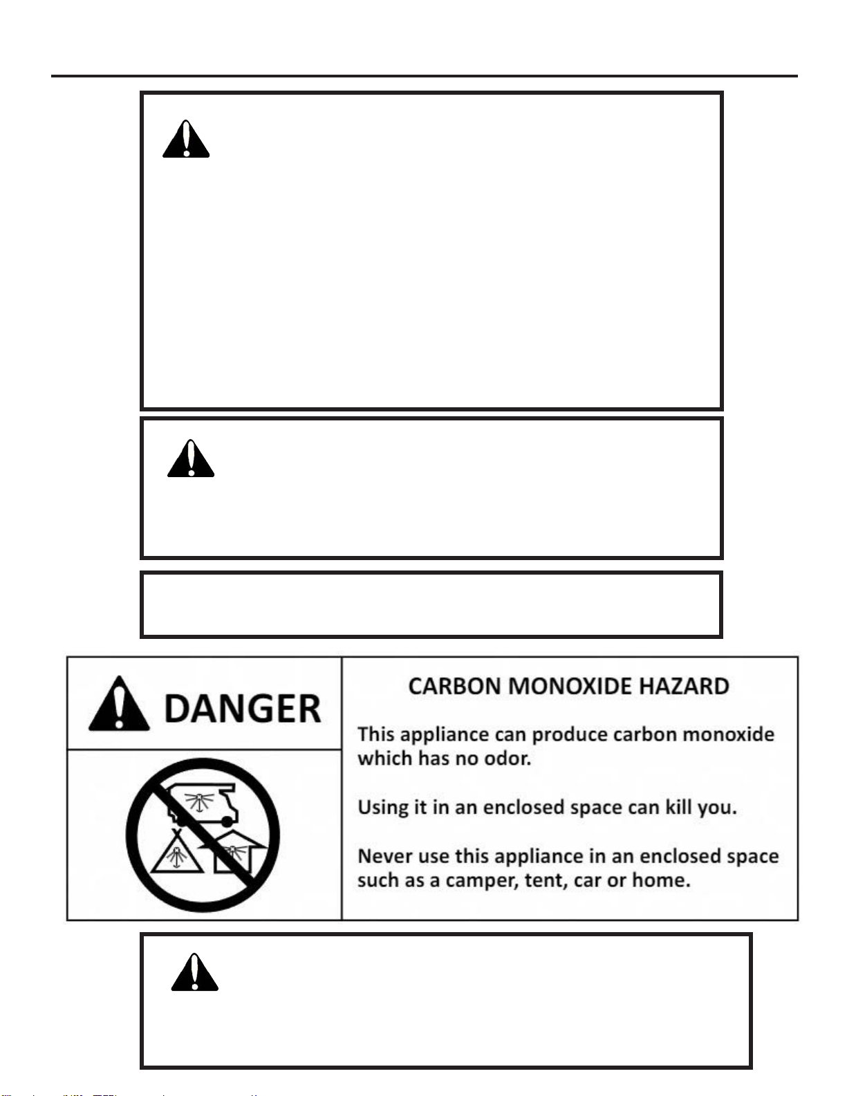
FOR YOUR SAFETY
• Always keep the area around these appliances clear
of combustible material, gasoline and other ammable
liquids and vapours.
WARNING: Failure to position the parts in accordance
with the diagrams in this booklet, or failure to use only
parts specically approved with this appliance, may
result in property damage or personal injury.
• Never use solid fuels such as wood, paper, cardboard,
coal, or any ammable liquids, etc., in this appliance.
• Do not use this appliance if any part has been under
water. Immediately call a qualied service technician
to inspect the appliance and to replace any part of
the control system or any gas control which has been
under water.
• Toddlers, young children and others may be
susceptible to accidental contact burns. To restrict
access to the appliance install an adjustable safety
gate to keep toddlers, young children and other at risk
individuals away from hot surfaces.
IMPORTANT NOTICE (Regarding rst re
up): When the unit is turned on for the rst time,
it should be turned onto high for the rst 4 hours.
This will cure the paint, logs and other products
used in the manufacturing process. The unit will
start to smoke and can irritate some people.

4
Table of Contents
Safety Precautions ..................................................................................................................... 2
Table of Contents ........................................................................................................................ 4
Codes And Approvals .................................................................................................................. 5
Specications ............................................................................................................................. 6
Dimensions: ................................................................................................................................. 6
Rating Label Location: .................................................................................................................... 6
Lighting Instructions: ..................................................................................................................... 6
Operating Instructions ............................................................................................................... 7
Wall Switch & Battery Backup: ........................................................................................................ 7
Pilot Light: .................................................................................................................................... 7
Routine Maintenance: .................................................................................................................... 7
Cleaning The Firebox: .................................................................................................................... 7
Cleaning Decorative Surfaces: . ........................................................................................................ 7
Maintenance And Service ............................................................................................................ 8
Burner Assembly Removal: ............................................................................................................. 8
Burner Shutter Cap Adjustment: ..................................................................................................... 9
Component Access: ......... ............................................................................................................. 9
Fuel Conversion: ...........................................................................................................................10
Initial Installation .................................................................................................................... 12
Introduction: ...............................................................................................................................12
Unit Install Preparation: ................................................................................................................12
Placement and Framing: ...............................................................................................................13
Installation Restrictions: ................................................................................................................15
Permitted Layouts: .......................................................................................................................15
Minimum Enclosure Clearances: ....................................................................................................16
Clearances & Non-Combustible Materials: ......................................................................................17
Mantel Clearances: .......................................................................................................................18
TV Installation Recommendation: ..................................................................................................19
Gas Line Connection and Testing: .................................................................................................20
Electrical Requirements & Wiring Diagram: .....................................................................................21
Secondary Installation .............................................................................................................. 22
Liner Installation: .........................................................................................................................22
Log Set & Media Installation .........................................................................................................23
Troubleshooting ....................................................................................................................... 26
Parts List ................................................................................................................................... 27
Parts Diagram ........................................................................................................................... 28
Warranty ................................................................................................................................... 29
Installation Data Sheet ............................................................................................................. 30

5
In the USA: The appliance may be installed at higher altitudes. Please refer to your American Gas
Association guidelines which state: the sea level rated input of Gas Designed Appliances installed at
elevations above 2000 (610 m) feet is to be reduced 4% for each 1000 feet (305 m) above sea level.
Refer also to local authorities or codes which have jurisdiction in your area regarding the de-rate
guidelines.
In Canada: When the appliance is installed at elevations above 4500 feet (1372 m), the certied high
altitude rating shall be reduced at the rate of 4% for each additional 1000 feet (305 m).
• This appliance has been tested by INTERTEK and found to comply with the established
OUTDOOR DECORATIVE GAS APPLIANCE standards in CANADA and the USA as follows:
OUTDOOR DECORATIVE GAS APPLIANCE (U44I-OUT; NATURAL GAS, PROPANE GAS)
CERTIFIED TO: ANSI Z21.97 / CSA 2.41 OUTDOOR DECORATIVE GAS APPLIANCES
CSA 2.17 GAS FIRED APPLIANCES FOR HIGH ALTITUDES
This Urbana U44I-OUT Outdoor Decorative Appliance:
• Is not a source of heat.
• Is not permitted for use with a thermostat or other automatic means of cycling the burner.
• Has been certied for use with either natural gas or propane (see rating label).
• Is not for use with solid fuels.
• Is not for use with glass doors or glass barriers.
• Is not for use with venting.
• This installation must conform to local codes or, in the absence of local codes, with the National Fuel
Gas Code, ANSI Z223.1 / NFPA 54; National Fuel Gas Code; Natural Gas and Propane Installation Code,
CSA B149.1; or Propane Storage and Handling Code, CSA B149.2, as applicable;
Codes And Approvals
• To prevent injury, do not allow anyone who is unfamiliar with the stove to
operate it.
• This installation must be electrically grounded in accordance with local codes,
or in the absence of local codes, with the National Electrical Code, ANSI/NFPA
70; or the Canadian Electrical Code, CSA C22.1, if applicable;

6
Specifications
Rating LabeL Location:
Figure 1: U44I-OUT Unit Dimensions
The rating label is attached to a length of wire
and is never to be tampered with or removed. All
important information for your replace is on this
label as well as the model specic serial number
which you will need for warranty information. The
rating label is located underneath the lava rock
media on the left side of the rebox.
Dimensions:
38 3/4"
(984mm)
41"
(1041mm)
37"
(940mm)
47 1/2"
(1206mm)
3" (76mm)
14 1/2"
(368mm)
17 1/8"
(435mm)
Incoming
120VAC
Wall Switch
Cable
44 3/4" (1137mm)
21 1/8"
(536mm)
3" (76mm)
Gas Inlet
3/8” NPT
Male
Lighting instRuctions:
Figure 2: Lighting Instruction Label
TURN ON: To turn on the fireplace push the
switch lever up into the ON position.
TURN OFF: To turn off the fireplace push the
switch lever down into the OFF position. 5
minutes must elapse prior to turning the
fireplace back on.
WARNING: IF YOU DO NOT FOLLOW THESE
INSTRUCTIONS EXACTLY, A FIRE OR EXPLOSION
MAY RESULT CAUSING PROPERTY DAMAGE,
PERSONAL INJURY OR LOSS OF LIFE.
This appliance is equipped with an ignition device
which automatically lights the pilot and main burner.
DO NOT try to light the pilot or burner by hand.
C-16791
The lighting instructions for the replace are
located on the back of the battery holder stowed
inside the wall switch box.

7
Operating Instructions
For Your Safety, Read Safety Precautions And
Lighting Instructions Before Operating
PiLot Light:
The pilot ow adjustment is set to maximum at the factory and should
not need to be adjusted. The pilot ame should cover ⅜” to ½” (10
to 13mm) of the ame sensor (see Figure 4). However, should the
need arise, turn the adjustment screw to alter the pilot gas ow.
Note: If the pilot requires adjustment it should be done prior
to completing the installation of the appliance. The valve is only
accessible through the rebox access panel.
Figure 3: Wall Switch
.375
-.500
(10-13mm)
Flame Sensor
Routine maintenance:
Run through the following procedures to ensure the system is clean and working properly at least once
a year. Check the burner to see if all the ports are clear and clean. Check the pilot to make sure it is not
blocked by anything. The pilot ame should be blue with little or no yellow tips.
WARNING: Failure to position parts in accordance with this manual, or failure to use only parts specically
approved with this appliance may result in property damage or personal injury.
cLeaning the FiRebox (RecommenDeD annuaLLy):
Carefully remove the logs, they are fragile. Gently remove all the media and place on a paper towel. Vacuum
the bottom of the rebox thoroughly. Carefully clean any dust o the logs and remove any lint from the
burner and pilot. At this time, inspect the burner tube for cracking or severe warping. If a problem is
suspected, contact the dealer. Check the logs for deterioration. Re-install the logs as shown in the Secondary
InStallatIon - log Set InStallatIon section. If new/more media is required, contact your nearest Urbana
dealer.
cLeaning DecoRative suRFaces:
Painted and porcelain faces should be wiped with a damp cloth periodically. Never clean the face when it is
hot. Do not use other cleaners as they may leave a residue, which can become permanently etched into the
surface.
WaLL sWitch & batteRy backuP:
Included with the replace is a weatherproof
wall switch and battery backup housing.
This wall switch comes pre-wired to a
14 foot length of 5-wire cable that can
be mounted externally in a convenient
location for replace operation. The 5-wire
cable connects directly to the replace’s
control board (see wiring diagram section).
The battery holder takes 4 x AA batteries
(supplied).
ON/OFF
Wall
switch
Battery
Backup
Door
Figure 4: Pilot Light

8
buRneR assembLy RemovaL:
1. Remove log set and lava rock media.
2. Remove the venturi cover box from the rear of
the rebox by lifting it up & o the two mount
screws.
3. Remove the Log Grate & wind deector glass by
removing the two (2) T-20 screws at the rear of
the grate and loosening the two screws holding
the log grate clamps in place near the front of
the grate (see Figure 6).
4. Remove the two (2) T-20 screws securing
the orice mount clamp onto the burner (see
Figure 7).
5. Remove the four (4) T-20 screws securing
the burner to the rebox (see Figure 8). The
burner can now be fully removed.
To re-install the burner, follow the steps above
in reverse. When placing the burner back in the
rebox, be sure not to move the air shutter. Do
not over tighten the burner screws or they
might strip; just get them snug.
Figure 5: Venturi Cover Box Removal
The burner will need to be removed for maintenance and fuel conversion. Follow the procedure carefully.
Proceed only when the unit has completely cooled down.
Figure 6: Log Grate Removal
Figure 7: Orice Clamp Screws
Maintenance And Service
Figure 8: Log Burner Mounting Screws

9
Maintenance And Service
1. The component access panel is located behind the right liner panel. Loosen the two (2) bolts on the right liner
retainer using a 5/16” socket until it can be removed. See Figure 10.
2. Remove the right liner from the rebox. See Figure 11.
3. Using a T20 screwdriver remove the 12 screws from the black cover plate on the rebox side to gain
access to the component and connections.
Loosen
Figure 9: Shutter Cap Adjustment
Figure 10: Liner Retainer Removal
NG: 1/8 of full rotation open
LP: 3/4 of full rotation open
buRneR shutteR caP aDjustment:
The U44I-OUT contains an adjustable shutter cap that can alter the amount of air the burner receives.
This can greatly aect the quality of the burn, especially when converting the gas type for the unit.
Follow these steps carefully to properly set the shutter cap:
1. Remove the burner assembly from the replace as instructed on the previous page.
2. At the back of the burner (where the
burner connects to the burner orice),
there is a single Phillips head screw
that should be loosened. This will allow
for adjustment of the burner cap (see
Figure 9).
3. Rotate the shutter following the
guidelines below. These are general
settings only and the shutter may
require additional adjustment (less/
more) depending on the exact setup of
the appliance:
Figure 11: Right Liner Removal
moRe aiR
Less
aiR
comPonent access:

10
Maintenance And Service
FueL conveRsion:
TO BE INSTALLED BY A QUALIFIED SERVICE AGENCY ONLY
Please read and understand these instructions before installing.
Warning: This conversion kit shall be installed by a qualied service agency in accordance
with the manufacturer’s instructions and all applicable codes and requirements of the
authority having jurisdiction. If the information in these instructions is not followed
exactly, a re, explosion or production of carbon monoxide may result causing property
damage, personal injury or loss of life. The qualied service agency is responsible for
the proper installation of this kit. The installation is not proper or complete until the
operation of the converted appliance is checked as specied in the manufacturer’s
instructions supplied with the kit.
Kit Parts List for all U44 Models:
1 - LP ON/OFF Plate
1 - Burner Orices (LP: #36)
1 - Pilot Orice (NG: 0.2) or (LP: 0.14)
conveRsion kit instaLLation:
1. Disconnect the gas supply completely as well as any electrical power source before proceeding.
2. Remove safety screen (if installed), log grate, and burner (see MaIntenance and ServIce section of Owner’s
Manual).
3. Convert the existing burner orice with the ones provided in this kit using a 1/2 inch socket.
2 - Conversion Labels [included with unit]
Carefully inspect all parts supplied with this conversion kit. If any parts have been damaged or are missing,
contact your dealer, distributor or courier company to have them replaced before starting this installation.
Figure 12: Orice Location
4. Remove the pilot shield from the
pilot assembly (see Figure 13).
5. Convert the existing pilot orice
using a 7/16 inch wrench. Loosen
the pilot head, rotate counter
clockwise and fully remove.
Remove the existing orice and
replace with the one supplied in
the kit (Figure 14). Re-install the
pilot head and tighten back to its
original position (Figure 15).
6. Convert the gas valve:
a) Remove the existing NG
ON/OFF plate using a T-20
screwdriver.
b) Remove the rubber
diaphragm; do not reuse.
c) Install the new LP ON/OFF
plate with integrated diaphragm
assembly using longer hardware.

11
Maintenance And Service
7. Adjust the burner shutter cap to the proper setting (see section
MaIntenance and ServIce - Burner Shutter cap adjuStMent on
page 9).
8. Reinstall the burner, log grate, lava rock and logs (see appropriate
MaIntenance and ServIce sections).
9. Purge any air from gas line and reconnect to unit.
10. Use a small brush and apply a warm soapy water solution to all
gas connections. If a gas leak is present, bubbling will occur. Gas
leaks can be repaired by using a gas approved pipe thread sealant.
WARNING: NEVER USE AN OPEN FLAME WHEN TESTING
FOR GAS LEAKS.
11. Reconnect electrical power to the unit.
12. Light the pilot and recheck for leaks in the aluminum pilot line.
If a leak is evident, contact your Urbana dealer for a pilot line
replacement. WARNING: DO NOT ATTEMPT TO FIX THIS
LINE, IT MUST BE REPLACED IF DAMAGED. The pilot should
properly cover the thermocouple. If adjustment is necessary, turn
the adjustment screw in the valve (see page 20) clockwise to
decrease and counter-clockwise to increase until the correct ame
is achieved.
13. Start the main burner and verify full operation. Conrm the inlet
and manifold gas pressures are within the acceptable range using
a manometer (see InItIal InStallatIon - gaS lIne connectIon
and teStIng). If this unit has been installed at an altitude
higher than 2000ft (610m) it is required to de-rate the unit
accordingly.
In the USA: The appliance may be installed at higher
altitudes. Please refer to your American Gas Association
guidelines which state: the sea level rated input of Gas
Designed Appliances installed at elevations above 2000 (610
Figure 13: Pilot Shield Removal
Figure 14: Pilot Orice
Figure 15: Correct Pilot Position
m) feet is to be reduced 4% for each 1000 feet (305 m) above sea level. Refer also to local authorities or
codes which have jurisdiction in your area regarding the de-rate guidelines.
In Canada: When the appliance is installed at elevations above 4500 feet (1372 m), the certied high
altitude rating shall be reduced at the rate of 4% for each additional 1000 feet (305 m).
14. MAKE SURE that the conversion labels provided are installed on or close to the rating label to signify
that the unit has been converted to a dierent fuel type.

12
Initial Installation
QUALIFIED INSTALLERS ONLY
intRoDuction:
This section of the owner’s manual is for the use of qualied technicians only. There are several installation
safety guidelines that must be adhered to; please carefully read the safety precautions at the front of this
manual.
unit instaLL PRePaRation:
There are four (4) nailing anges (2 per
side) to secure the unit to the framing,
they are assembled at from the
factory (see Figure 16). Flip the nailing
anges up 180 degrees and secure
in place using the T-20 screws above
pre-installed in the cabinet. Bend the
anges 90 degrees making them ush
with the cabinet face (see Figure 17).
Figure 16: Nailing Flange Flat Figure 17: Nailing Flange
Assembled
naiLing FLanges:
Please review the following instructions carefully to ensure the unit is prepared properly before installation.
1. Bend top standos by hand to form general shape
(see Figure 18).
Figure 18: Top Standos
toP stanDoFFs:
2. Install top standos into position using supplied T-20
screws (see Figure 18).
There are four (4) standos on top of the replace that
are assembled at from the factory (see Figure 18). When
assembled, these standos create the required clearance
for an enclosure made of combustible material.

13
Initial Installation
QUALIFIED INSTALLERS ONLY
PLacement anD FRaming:
- The location for the appliance can be raised, at oor level, or installed in a corner. There are minimum
framing measurements for each situation. The appliance must be placed on a solid and level oor.
- A protective hearth is not required in front of the replace
- The basic rough opening should have the dimensions as shown above. The appliance must be placed on a
strong and level surface.
- The replace cannot serve as part of the building’s insulation or weatherproong barrier. The building must
be properly insulated and sealed from the outside prior to installation of the replace. Avoid the possibility of
vapour barrier coming in direct contact with the replace chassis.
- If masonry is to be used, prepare the necessary foundation for the masonry load. When masonry construction
is being used, a lintel must be used over top of the appliance to support the added weight. Consider the height
of hearth nish material (stone, brick, etc.) if building a appliance platform. The bottom of the replace must
be level with nished hearth.
-The gas line must be run to the right side of the appliance, there is a 3/8 NPT tting to connect the gas line
to. The electrical wiring must also be brought to the right side.
Figure 19: U44I-OUT Minimum Framing
73”
1854 mm
45”
1143 mm
47 ½”
1206 mm
21 ¼” / 540 mm
Combustible Enclosure
Non-Combustible Enclosure*
39”
991 mm
*Removal of top standos required

14
Initial Installation
QUALIFIED INSTALLERS ONLY
Figure 20: Square / Alcove Installation
78”
[1981mm]
55¼”
[1403mm]
41”
[1041mm]
18”
[457mm]
48”
[1219mm]
Parallel Wall Clearance
21¼”
[540mm]
12”
[305mm]
12”
[305mm]
41”
[1041mm]
45”
[1143mm]
Figure 21: Corner Installation
These are the minimum allowable framing dimensions required to safely operate the replace. Plan your entire
installation before proceeding.
Some considerations prior to picking a location:
- Conrm the desired location has adequate ventilation/air ow
- Avoid areas where running water or ooding could pose an issue
- Avoid areas susceptible to direct high winds. High wind will cause the ame to behave erratically and
potentially cause a pilot or burner outage. This ame behaviour will also leave undesired black soot on the log
set and side liner
- Any outdoor furnishings must be kept a minimum of 3ft (0.9m) away from the front of the replace

15
- 4 walls (1 with a permanent opening at ground level) and no overhead cover
- Overhead cover with no more than 2 sidewalls either perpendicular to each other or parallel
(breezeway)
- Overhead cover with 3 sidewalls constructed with at least 30% of each wall’s area open and
unrestricted.
Figure 22: Fireplace Installation restrictions, refer to Table 1
Initial Installation
QUALIFIED INSTALLERS ONLY
A
C & D
BE
B
B
K & L JF & G
H
Fireplace Air Supply Inlet Gas MeterG
G
Restricted Zone
(Fireplace not allowed)
I
Letter Canadian Installation 1US Installation2Description
A0 (0 cm) Clearance above grade, verandah, porch, deck, or balcony.
B12 in (30 cm)*Clearance from window or door.
C 36 in (91.4 cm) Clearance to ventilated or unventilated sot.
D60 in (1524 cm) Clearance to vinyl sot
E 12 in (30 cm) Clearance to outside corner.
F12 in (30 cm) Clearance to inside corner.
G36 in (91.4 cm) Clearance to inside corner - vinyl siding
H 3 ft (91 cm) 3 ft (91 cm)* Radial clearance around service regulator vent outlet.
I12 in (30 cm)* Clearance to non-mechanical air supply inlet to building, or
the combustion air inlet to any other appliance.
J6 ft (1.83 m) 3 ft (91 cm) above if within 10
ft (3 m) horizontally
Clearance to mechanical air supply inlet.
K+36 in (91.4 cm) Clearance under verandah, porch, deck, or balcony.
L+60 in (1524 cm) Clearance under verandah, porch, deck, or balcony cladded
with vinyl
Table 1: Fireplace Installation Clearances
instaLLation RestRictions:
1 In accordance with the current CSA B149.1, Natural Gas and Propane Installation Code.
2In accordance with the current ANSI Z223.1 NFPA 54, National Fuel Gas Code.
* These numbers are only estimates.
+ Permitted only if verandah, porch, deck, or balcony is fully open on a minimum of two sides beneath the oor.
Clearances must be in accordance with local installation codes and requirements of the gas supplier.
PeRmitteD Locations:

16
minimum encLosuRe cLeaRances:
Minimum Enclosure -
Combustible Materials:
The minimum enclosure height required
when using combustible materials is 47 1/2”
(1206mm) as shown on the left. Combustible
nishing material is NOT permitted to be
installed over top of non-combustible material
within the 12” (305mm) non-combustible
zone above the replace opening.
Initial Installation
QUALIFIED INSTALLERS ONLY
37"
(940mm)
12" (305mm)
Non-Combustible
Zone
Fireplace
Opening
8 ¾"
(222mm)
Wood Headers
47 1/2"
(1206mm)
37"
(940mm)
Fireplace
Opening
Steel Headers
(not supplied)
39"
(991mm)
Non-Combustible
Material
Minimum Enclosure -
Non-Combustible Materials:
The minimum enclosure height may be
reduced to 39” (991mm) when using non-
combustible materials as shown on the left.
Top standos will need to be removed from
the replace to achieve this lower enclosure
height. Combustible nishing material is NOT
permitted to be installed over top of any non-
combustible material used for this installation.
Figure 23: Minimum Enclosure Height - Combustible Material
Figure 24: Minimum Enclosure Height - Non-Combustible Material

17
Figure 25: Non-Combustible Zones
cLeaRances & non-combustibLe mateRiaLs :
non-combustibLe mateRiaLs: Any construction or nishing material that is tested to ASTM E136 - Standard
Test Method for Behavior of Materials in a Vertical Tube Furnace at 750°C. Examples of non-combustible
materials are steel, stone, ceramic tiles, HardieBacker® cement board etc. Fire rated drywall (Type X) is
not an acceptable replacement for non-combustible material.
Facing above FiRePLace*: Non-combustible material is required a minimum 12” (305mm) above the
replace opening. Vinyl siding is not permitted between the replace opening and the external
ceiling/overhang.
Facing besiDe FiRePLace*: Non-combustible material, a minimum 4” (102mm) wide, is required down each
side of the replace opening.
*An outdoor high temperature sealant rated to 350°F (176°C) is required along the exposed edges
of the non-combustible materials and the replace to prevent water/moisture from entering the
enclosure.
heaDeR: The header can be made up of wood 2x4 construction at or above the top standos.
beLoW FiRePLace: It is recommended the appliance sit a solid and level surface
aDjacent/siDeWaLL: There must be a minimum distance of 12” (305mm) from the replace opening to an
adjacent wall composed of combustible material.
Initial Installation
QUALIFIED INSTALLERS ONLY
12"
(305mm)
49" (1245mm)
4" (102mm)
49"
(1245mm)
Non-Combustible Zones

18
Initial Installation
QUALIFIED INSTALLERS ONLY
manteL cLeaRances:
37"
(940mm)
4" - 12" Max.
(102 - 305mm)
25"
(635mm)
12" (305mm)
Non-Combustible
Zone
36" (914mm)
Min. Ceiling
From Opening
73" (1854mm)
Min. Celing
From Floor
Fireplace Opening
12" (305mm)
Non-Combustible Zone
4" (102mm)
12" Max. (305mm)
4" (102mm)
Fireplace Opening
For regular installations a mantel is not required. If a
mantle is desired, gures 26 and 27 show the minimum
required heights for both combustible and non-
combustible mantles. Maximum nished mantle depth
cannot exceed 12” (305mm). If you plan to install
a TV above your replace a non-combustible
mantle must be used. See the next page for further
information.
Figure 26: Combustible Mantle Clearance
Figure 27: Non-Combustible Mantle Clearance

19
Initial Installation
QUALIFIED INSTALLERS ONLY
tv instaLLation RecommenDation:
If you are planning to mount a TV above your replace some considerations must be made to ensure
it is protected from the heat. A recess and non-combustible mantel will be required in order to keep
the heat away from the TV. Flat wall installations are not permitted. There is no guarantee that this
installation will protect your TV. Make sure to consult your TV manufacture’s specications to nd the maximum
allowable operating temperature. Since every home and installation is unique, temperatures should be veried at
the time of install if possible. A TV should not be installed if temperatures exceed the manufacturers maximum
allowable temperature.
Figure 28: Recess Minimum TV Install
12" (305mm)
Non-Combustible
Zone
Fireplace
Opening
4” (102mm) Min.
Min. Recess Depth =
TV Flush with
Wall Surface
12” (305mm)
Non-Combustible
Mantle

20
gas Line connection anD testing:
WARNING: Only persons licensed to work with gas piping may make the necessary gas connections to this
appliance.
GAS LINE CONNECTION
• This appliance is equipped with a rigid pipe located on the right side of the unit terminating in a 3/8”
Female NPT tting. Consult your local authorities codes or the CAN/CGA B 149 (1 or 2) installation code
in Canada, or in the USA gas installations follow either local codes or the current edition of the National
Fuel Gas Code ANSI Z223.1.
• Where required by certain jurisdictions, this appliance may require an externally accessible gas shut o
valve i.e. Dante valve or the like.
Figure 29: Fully Labeled Gas Valve.
Table 2: Pressure and BTU Information.
The appliance and its shuto valves must be disconnected from the gas supply piping system during any
pressure testing where the pressure exceeds ½ PSIG (3.45 KPa) or damage will occur to the valve.
The appliance must be isolated from the gas supply piping system by closing its individual manual shuto
valve during any pressure testing of the gas supply piping system at test pressures equal to or less than ½
psig (3.45 KPa).
Always check for gas leaks with a soap and water solution after completing the required pressure
test.
TO TEST VALVE PRESSURES
The pressure taps are located on the
top right of the valve shown above
• Turn set screw 1 turn counter
clockwise to loose.
•Place 5/16” (8 mm) I.D. hose over
pressure tap system.
• Check pressures using a
manometer.
• When nished, release pressure,
remove hose & tighten set screw.
Natural Gas Propane
Main Orice #23 #36
Manifold Pressure 3.5” W.C. (0.87 KPa) 10.0” W.C. (2.49 KPa)
Max Supply Pressure 7.0” W.C. (1.74 KPa) 11.0” W.C. (2.74 KPa)
Min. Supply Pressure 4.5” W.C. (1.12 KPa) 10.4” W.C. (2.59 KPa)
Max BTU/hr Input 63,000 BTU/hr (18.4 KW) 71,000 BTU/hr (20.8 KW)
NEVER USE AN OPEN FLAME FOR LEAK TESTING.
Initial Installation
QUALIFIED INSTALLERS ONLY
Manifold Pressure Tap
Inlet Pressure Tap
Pilot Adjustment Screw
Gas Flow
Direction
Table of contents
Popular Outdoor Fireplace manuals by other brands

OFYR
OFYR PRO Series manual

Outdoor GreatRoom Company
Outdoor GreatRoom Company WP-1616 installation instructions

Heatmaxx
Heatmaxx SRCH06D manual

HAMPTON BAY
HAMPTON BAY 100 Use and care guide

StoneAge
StoneAge Square Fire Pits Installation and operating instructions

OW Lee
OW Lee CASUAL FIRESIDE 51-136 owner's manual