urmet domus Fdi IPASSAN User manual

IPASSAN - INSTALLATION GUIDE
+
50-001-652.B

1 Overview 3
1.1 Features 3
1.2 Hardware 3
1.2.1 Controllers 3
1.2.2 Extra modules 5
1.3 IPassan manager 7
2 Installation 7
2.1 Controller 7
2.1.1 Power supply 7
2.1.2 Controller tamper 9
2.1.3 RS485 main 8
2.1.4 RS485 Auxiliary 9
2.1.5 TCP/IP 9
2.1.6 Readers 10
2.1.7 Lock 11
2.1.8 REX push button 12
2.1.9 Door contact 12
2.2 Door extension card 13
2.2.1 Psu 13
2.2.2 Readers, door contact, lock, etc 13
2.3 Inputs or outputs RS485 expander 13
2.3.1 Psu 13
2.3.2 RS485 bus 14
2.3.3 12Vdc output 14
2.3.4 Inputs 14
2.3.5 Outputs 15
2.4 Inputs / outputs expansion card 15
2.4.1 Psu 15
2.4.2 Inputs 15
2.4.3 Outputs 15
2.4.4 Mode maintenance 15
3 Led indication 16
4 First start 16
4.1 Server controllers communication over Internet 18
4.2 Software installation 18
4.3 IP setting 18
4.4 Manually add a device 19
4.5 Auto detection 19
CONTENT

1 - OVERVIEW
50-001-652.B FDI MATELEC SA Route de St Symphorien 85130 Les landes Génusson - France www.fdimatelec.com 3
IPassan system
IPassan is a full solution to manage door and lift access control, doorphone system, cctv and is also open to extra fea-
tures such as intruder alarm, counting, etc...
It is designed to be as exible and scalable as possible through expansion cards.
The monitoring of the building is also part of the system so that the operator is always able to turn on/off the security of
a door, a oor and is aware of a door left opened.
The system is based on controllers, expanders and optional cards you can plug and /or connect together in order to
create a mix of doors, lifts, inputs and outputs.
All those devices communicate together via a FDI encrypted protocol.
1.1 Features
• Up to 64 controllers per network (384 doors) in TCP/IP
• Multi network per site, unlimited number of doors, inputs, outputs per site
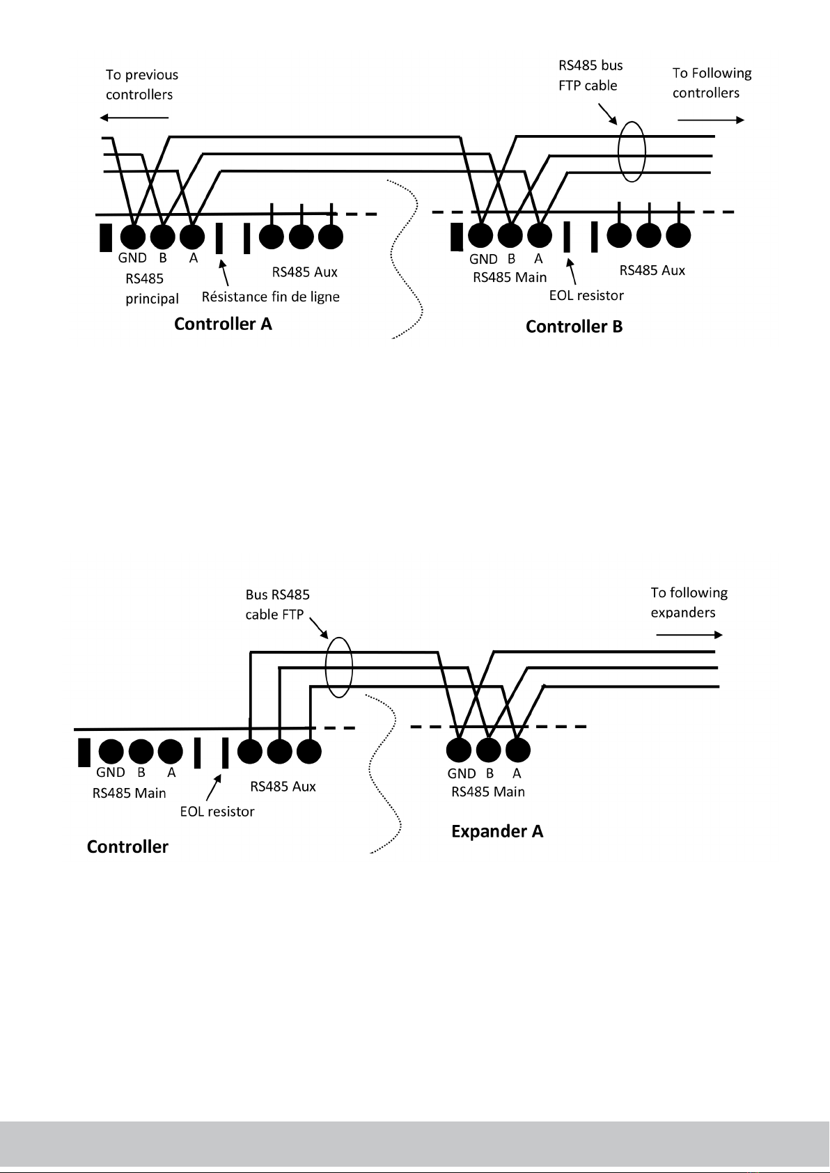
• Up to 32 controllers per RS485 bus (64 when the network is a mix of TCP/IP and RS485)
• Up to 14080 inputs or outputs per network (220 per controller with expansion modules)
• Encrypted RS-485 and 2 wire bus communications
• USB or TCP/IP communication with the server
• Transfer from both sides (server to controllers or controllers to server)
• Full monitoring of all sites (networks, controllers, expanders, 2-Smart readers)
• Upgradable rmware of all devices (controllers, expanders, 2-Smart readers)
1.2 Hardware
1.2.1 Controllers
The controllers are the central processing of the system. The controller is designed to manage 2 or 4 doors (it depends
on the reader technology) and manage up to 6 doors with an optional door card.
The computer controller communication is USB through a dedicated plug or TCP/IP (with the dedicated controllers).
Two different technologies are available: FDI 2 wire bus called 2-SMART (owner, encrypted bus) or standard Wiegand.
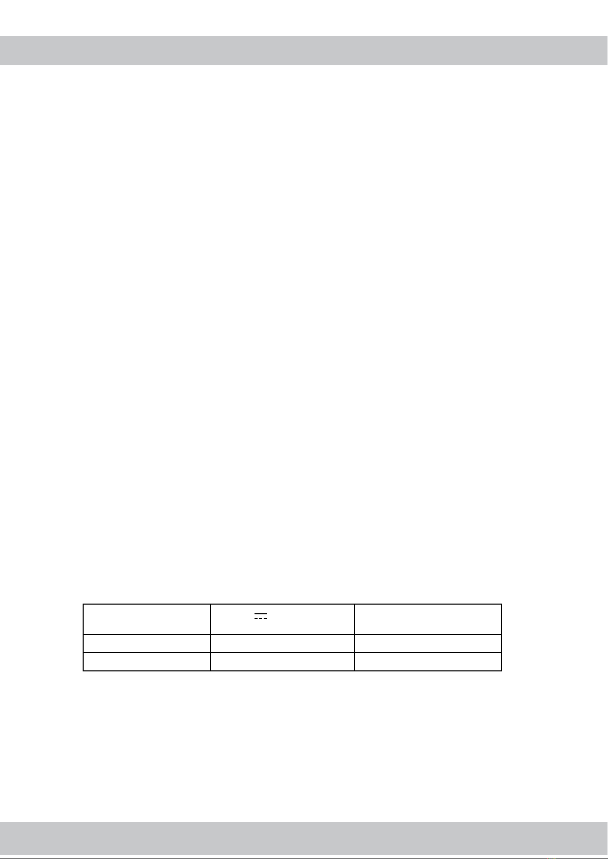
So there is not only one controller but four different part numbers:
12V psu 24/48V & POE (Power over
Ethernet)
Wiegand readers 2 doors / 2 Wiegand readers 2 doors / 2 wiegand readers
2-Smart readers 4 doors / 2-Smart readers 4 doors / 2-Smart readers

50-001-652.B FDI MATELEC SA Route de St Symphorien 85130 Les landes Génusson - France www.fdimatelec.com 4
Features
• 2 RS485 bus
- Main RS485 bus between controllers
- Slave RS485 bus between controller and expanders
• Encrypted RS-485 and 2 wire bus communications (2-SMART)
• USB plug (data backup, computer connection)
• Built in Ethernet interface (POE depends on the part number)
• 4 doors (2 doors with Wiegand readers)
- 1 reader
- 1 REX
- 1 door contact
- 1 door relay
• 12Vdc +/- 15% outputs for the readers (80mA max per reader)
• Tamper
• Transfer from both sides (server to controllers or controllers to server)
• Monitoring of the site (controllers, expanders, 2-Smart readers)
• Upgradable rmware of all devices (controllers, expanders, 2-Smart readers)
Ethernet POE (Optionnal)2 RS485 bus (main, expanders)
1 micro USB OTG port
doors
Specifications
• Power Supply 12Vdc (up to 1A with 6 readers)
• 12Vdc +/- 15 % output 80mA per reader
• Ethernet Fixed IP or DHCP
• USB master or slave depending on the setting
• Door relay 48Vdc 2A
• REX input Protected by optocoupler
• Door contact input EOL management
• Tamper Normally closed
• Dimensions 183mm X 234mm
• Operating temperature -10° + 60°
• Humidity 85% RH ( Relative humidity) max
• Storage -20°C /+ 70°C
- Risk of explosion if CR2032 battery is replaced by an incorrect type
- This equipment must be powered by ES1/PS2 circuits.

50-001-652.B FDI MATELEC SA Route de St Symphorien 85130 Les landes Génusson - France www.fdimatelec.com 5
10 inputs 10 outputs
1.2.2 Extra modules
Different optional devices have been designed to increase the capacity and / or the features of the system. Two different
types of devices are offered:
The expanders are connected to the secondary RS485 bus of a controller and powered through an extra psu. Each
controller manages up to 10 expanders which could be distant of 1000 meters from the controller.
The optional cards are plugged on the controller or on the expander. Il could be extra doors, extra inputs or extra out-
puts.
1.2.2.1 Expander
Two types are available: 10 inputs or 10 outputs.
Both expanders are designed to receive an extra card (12 inputs or 12 outputs)
• The 10 input expanders are useful to manage extra devices (sensors for example). The values of the end of
line resistors are settable in the system.
• The 10 output expanders provide dry contacts and are used for lift management for example
Features
• RS485 bus with the controller (10 expanders max per controller)
• Secured RS485 bus
• Local psu. 12 to 24V Ac/dc
• 10 inputs (with end of line management) or 10 outputs (C, NO, NC 24Vdc / 2A) depending on the part number
• 12Vdc outputs 200 mA
• Monitored from the software
• Upgradable rmware
• Ability to manage an extra input / output expansion card (up to 22 inputs or outputs per expander)
Specifications
• Power Supply 12V to 24V or (up to 1A with 22 activated relays)
• 12Vdc output 200 mA
• Relay 48Vdc 2A
• Input EOL management (resistors can be set in the software)
• Dimensions 183mm X 234mm
• Operating temperature -10° + 60°
• Humidity 85 % RHmax
• Storage -20°C / +70°C
This equipment must be powered by ES1/PS2 circuits

Input / output expansion cards
Twelve inputs or outputs can be added onto a controller or expander by plugging an extra expansion card.
Those expansion cards are pluggable on the top of a controller or expander. In this case, the controller or expander
manages:
12 inputs added to
A controller 2x wiegand or 4x 2-Smart doors (included door contact) +
12 inputs
A 10 inputs expander 22 inputs per expander
A 10 outputs expander 10 outputs + 12 inputs per expander
12 outputs added to
A controller 2x wiegand or 4x 2-Smart doors (included door contact) +
12 outputs
A 10 inputs expander 12 outputs + 10 inputs per expander
A 10 outputs expander 22 outputs per expander
50-001-652.B FDI MATELEC SA Route de St Symphorien 85130 Les landes Génusson - France www.fdimatelec.com 6
Door optional cards
Two or four doors can be added to the controller.
- 2 extra doors can be added to the 2 wire controller because it already manages 4 doors.
- 4 extra doors can be added to the Wiegand controller because it already manages 2 doors.
Features
• Pluggable on a controller
• Powered through the controller. Doesn’t need an extra psu
• 2 doors (4 doors with wiegand readers)
- 1 reader
- 1 REX
- 1 door contact
- 1 door relay
• 12Vdc outputs for the readers (80mA max per reader)
Specifications
• Power Supply 12Vdc supplied by the controller
• 12Vdc output +/- 15% 80mA per reader
• Door relay 48Vdc 2A
• REX input Protected by optocouppler
• Door contact input EOL management
• Dimensions 183mm X 70mm
• Operating temperature -10° + 60°
• Humidity 85 % RH max
• Storage -20°C / +70°C
12 inputs 12 outputs

2 - INSTALLATION
50-001-652.B FDI MATELEC SA Route de St Symphorien 85130 Les landes Génusson - France www.fdimatelec.com 7
1.3 IPassan manager
The software is web based and is designed to be installed on a computer or can be cloud based. For the Windows
release, the minimal conguration is :
- Quad core processor > 3Ghz (Intel Core i5 for example)
- 4Go Ram
- Operating system Windows 7 or higher
- Hard disk 10GB
- Network interface 100/1Go
- Internet connection to update the software and/or use the e mail service
The software is suitable for simple to big systems, multi sites, etc
The communication with the controllers is TCP/IP or USB with the rst one and RS485 with the others.
This equipment must be installed in a restricted area. Controllers and expanders are designed to be wall mounted
through 4 screws but can also DIN rail mounted without any extra device.
A cover is supplied with controllers and expanders.
The expansion cards are pluggable on the base (controller or expander), and don’t need extra psu.
Two screws are supplied to maintain the expansion card to the base. The cover is also supplied with four screws to x it
on the controller.
Metal enclosure
Two metal boxes are designed to receive 2 or 4 devices (controller or expander).
The two device box (left picture) is supplied with a 13.8V / 3A power supply.
The four device box (right picture) is supplied with a 13.8V / 7A psu.
Note, the batteries (12V / 7Ah) aren’t supplied.
2.1 Controller
The controllers can communicate through TCP/IP or through RS485.
2.1.1 Power supply
Depending on the part number, the controller is designed to work with 12Vdc psu or 24V/48V with POE (Power Over
Ethernet).
So 4 different controllers are available :
- 2 Smart controller 12Vdc
- 2 Smart controller 24/48Vdc/POE
- Wiegand controller 12 Vdc
- Wiegand controller 24/48Vdc/POE

50-001-652.B FDI MATELEC SA Route de St Symphorien 85130 Les landes Génusson - France www.fdimatelec.com 8
Note : when the controller is powered through the ethernet network (POE), the + and – terminals are not connected.
2.1.2 Controller tamper
The controller offers two different tamper inputs.
When the cover is placed on the controller, it pushes a reed switch (see below : built in tamper). An extra input is avai-
lable when the controller is xed in a metal enclosure. This contact must be normally closed (closed contact when the
cabinet is closed).
Note, both contacts are managed separately in the system. It manages different events when the cover is placed, remo-
ved and the enclosure opened / closed.
2.1.3 RS485 main
The RS485 bus authorizes up to 32 controllers within 1000 meters.
Note : The setting of the RS485 bus addresses is automatically done by the system, so there is no need for the installer
to set up switches.
Installation rules:
- The RS485 bus is sensitive to disturbance and requires a specic twisted and shielded cable (FTP).
- A and B signals must be connected on the same pair in the cable.
- The controllers include a jump (close to the RS485 terminal) which is an end of line resistor. Insert this jump
only at each side of the bus.

50-001-652.B FDI MATELEC SA Route de St Symphorien 85130 Les landes Génusson - France www.fdimatelec.com 9
2.1.4 RS485 Auxiliary
Each controller manages up to 10 expanders. Those expanders are connected through the auxiliary RS485 bus as
shown below.
Installation rules:
- The RS485 bus is sensitive to perturbation and requires a specic twisted and shielded cable (FTP).
- A and B signals must be connected on the same pair in the cable.
- The controllers provide a jump (close to the RS485 terminal) which is an end of line resistor. Insert this jump, or
add a 120 Ohms resistor between A and B for an expander, at each side of the bus.
2.1.5 TCP/IP
The system authorizes up to 64 controllers on a TCP/IP network. This means that the 64 controllers are able to commu-
nicate together (Apb zone or counting for example)
When the system requires more than 64 controllers, a second network has to be created in the software. All controllers
of the system communicate with the server (software), but controllers of a rst network can’t communicate directly to
controllers of a second network.

2-smart reader wiring
50-001-652.B FDI MATELEC SA Route de St Symphorien 85130 Les landes Génusson - France www.fdimatelec.com 10
2.1.6 Readers
Controllers are designed to work with 2 smart readers or Wiegand readers. Both ranges share the same aesthetics but
offer different features.
The wiegand is a common protocol in the access control market. When a key is presented to the reader, the serial num-
ber of the key is sent to the controller. So the communication is one way only.
2 smart readers manage a bi-directional communication between controllers and readers. This offers many advan-
tages:
- Own protocol, security
- Tamper management without extra wire
- Ability to load a new rmware from the controller
- Ability to increase the features of the reader
DS+
Note, the green led is ON while the relay is activated. The red led ashes once every 3 secs when the reader is working
ne and is ashing 3 times/sec if the reader is not connected or not answering to the controller.
DS-
Wiegand reader wiring
DS+
DS+
DS-
DS-
DS+

50-001-652.B FDI MATELEC SA Route de St Symphorien 85130 Les landes Génusson - France www.fdimatelec.com 11
Note, the green led of the controller is ON while the relay is activated. The red led ashes once when the controller
receives some data from the Wiegand reader.
The green led of the reader is activated for the door delay when a valid credential is used.
The red led of the reader ashes quickly (3 times per sec) when the credential is not authorized.
The buzzer is activated one sec when the credential is authorized and generate three short beeps when the credential
isn’t authorized.
The third led is not managed yet.
The tamper input is designed to manage events when the reader is removed from the wall (tamper).
2.1.7 Lock
Fail-secure lock
DS+
DS-

Fail-safe lock / Maglocks
2.1.8 REX push button
When a fail-safe lock is used, a second security must be used to prevent an issue between the REX push button and the
controller.
Basically, a break glass is connected in serial with the lock psu or the push button manages two dry contacts : 1 NO
contact for the controller REX input + 1 NC contact in serial with the lock or maglock psu. (see wiring diagram above)
When a fail secure lock is used, the REX push button is NO as shown below.
2.1.9 Door contact
The door contact management is provided in IPassan system to manage events as door left opened or forced door.
This door contact could be a dry contact only or with eol resistors. In this case, the R1 and R2 resistors are settable in
the software.
DS-
DS+
DS+
DS-
50-001-652.B FDI MATELEC SA Route de St Symphorien 85130 Les landes Génusson - France www.fdimatelec.com 12

50-001-652.B FDI MATELEC SA Route de St Symphorien 85130 Les landes Génusson - France www.fdimatelec.com 13
2.2 Door expansion card
A 2 smart reader door expansion card offers 2 extra doors to the base for a maximum of 6 doors per controller.
And a Wiegand reader expansion card allows the connection of 4 extra doors for a maximum of 6 doors per controller.
Please note that it is not possible to plug a Wiegand expansion card on a 2 smart reader one or a 2 smart expansion
card on a Wiegand controller.
Any input or output expansion card can be associated with the controllers.
2.2.1 Psu
The power supply is supplied by the controller itself.
2.2.2 Readers, door contact, lock, etc
The wiring is the same for the extension card as for the controllers. See chapter 2.1.6 Reader, 2.1.7 lock, 2.1.8 REX push
button, 2.1.9 door contact.
2.3 Inputs or outputs RS485 expander
The 10 output expander provides 10 dry contacts through 5A relays.
The 10 input expander offers 10 inputs with end of line resistor management.
2.3.1 Psu
By default:
R1 = 4,7 KΩ
R2 = 10 KΩ

50-001-652.B FDI MATELEC SA Route de St Symphorien 85130 Les landes Génusson - France www.fdimatelec.com 14
2.3.2 RS485 bus
Each controller manages up to 10 expanders. Those expanders are connected through the auxiliary RS485 bus as
shown below.
Installation rules:
- The RS485 bus is sensitive to disturbance and requires a specic twisted and shielded cable (FTP).
- A and B signals must be connected on the same pair in the cable.
- The controllers provide a jump (close to the rs485 terminal) which is an end of line resistor. Insert this jump, or
add a 120 Ohms resistor between A and B for an expander, at each side of the bus.
2.3.3 12Vdc output
The expander provides a 12Vdc output that can be used to power extra devices. This output is protected through a cur-
rent limiter (200mA).
2.3.4 Inputs
The input could be setup in the software as active /not active (2 levels) or with eol resistors (4 levels). When the box
“EOL resistors” is ticked, the values of both resistors must be entered so the system is able to calculate the thresholds.

50-001-652.B FDI MATELEC SA Route de St Symphorien 85130 Les landes Génusson - France www.fdimatelec.com 15
2.3.5 Outputs
The relays are fully independent
2.4 Inputs / outputs expansion card
2.4.1 Psu
The psu is provided by the controller or expander on which the expansion card is plugged.
2.4.2 Inputs
The 12 inputs work as described in the chapter 2.3.4
2.4.3 Outputs
The 12 outputs work as described in the chapter 2.3.5
2.4.4 Mode maintenance
A maintenance mode is designed to easily test the system.
In this position , the behavior of the controller is standard. Only authorized keys can open the door or activate
oors.
In the following position , any key opens any door (reader 1 => door 1, reader 2 => door 2, etc).
Please note that in the maintenance mode the controller does not link a reader to outputs so the lift management can’t
By default:
R1 = 4,7 KΩ
R2 = 10 KΩ
be tested in this mode.

50-001-652.B FDI MATELEC SA Route de St Symphorien 85130 Les landes Génusson - France www.fdimatelec.com 16
3 - LED INDICATION
Different leds on the controller or expander provide a status of the communication, psu, etc...
• Status of the output relay
• Status of the input relay
• Communication with the server
Overview
Door status
For each door, the green led is
ON when the relay is activated.
The red led of a 2-Smart control-
ler ashes once every 3secs when
the reader communication is ok
and ashes 3 times per sec in
case of faulty communication
(reader not connected or tamper).
RS485 main bus (controllers)
On a main controller (one per
rs485 network), this led is on all
time.
On another controller, it ashes
once every 3 secs.
It is off when there is no activity
on the rs485 bus (main or slave).
DS+
DS-

50-001-652.B FDI MATELEC SA Route de St Symphorien 85130 Les landes Génusson - France www.fdimatelec.com 17
RS485 auxiliary bus (expanders)
The status led is on when the
controller communicates with
expander(s).
It is off when there is no commu-
nication on this auxiliary bus.
Controller status
Two leds show the right voltage
of the processing unit (green led)
and the right performance of the
operating mode.
The green led must be on. If it is
off, check the psu.
The red led ashes once per sec,
if it is off or always on, restart the
controller.
If, after a re boot, the led is
always on or off, the controller
has to be replaced.
Server communication
A green led is on when the
controller is connected to the
server.
4 - FIRST START
Each controller and expander is supplied with a single serial number which includes a checksum to avoid any faulty
entry.
Write out those serial number on site to setup the system in the software.
Note, by default, the tcp/ip conguration of the controller is setup to dhcp. This means that when the controller is powe-
red, it asks for an ip address to the dhcp server. If there is no answer, the controller takes the following setting :
Ip address 192.168.1.250
Mask 255.255.255.0
Gateway empty eld
The controller is also designed to work with static Ip address. See chapter 4.3.
Two ways are planned to setup the site :
- Add controllers and expanders then enter the serial number in the software. This choice is useful when the
site conguration is done before wiring the devices on site.
- Use the built-in tool to detect the controllers and expanders then select those belong to your site.

50-001-652.B FDI MATELEC SA Route de St Symphorien 85130 Les landes Génusson - France www.fdimatelec.com 18
4.1 Server controllers communication over Internet
In the Ipassan system, the controller asks to the server if it has any new data to download. This means the server IP
address has to be setup in the controllers.
This setting is automatically done by the communication server when a controller is added to the site.
When controllers are managed through internet. The server is not able to communicate with them. FDI provides an
extra tool Ipsearch which has to be launched on the same network than the controllers and which offers the possibility
to change the IP setting and the server Ip address the controller has to join.
On this specic case, a nat (network address translation) has to be setup in the rooter on the server side not on the
controller side(s).
This also means that the system doesn’t require public static IP on the controller sides.
4.2 Software installation
See Ipassan manager install guide.
4.3 IP setting
If the controllers have to be installed on an existing network, ask the IT manager for the IP setting (dhcp or static).
In case of static IP, one Ip address is required for each controller connected to the IP network. The extra controllers
connected to the server through Rs485 and a rst TCP/IP one doesn’t require an Ip address.
If the dhcp mode is selected, you just need to connect the controllers to the network.
If the controllers use static IP addresses, don’t connect all new controllers in the same time because all those control-
lers will have the same 192.168.1.250 Ip address and this will generate IP conicts.
In this case, follow these steps :
1) connect a rst controller to the IP network
2) add the controller in the software as describe in the 4.4 chapter (manually adding) or 4.5 chapter (auto
detection adding)
3) Enter a valid Ip address, mask, gateway, etc for this controller then click on Save

50-001-652.B FDI MATELEC SA Route de St Symphorien 85130 Les landes Génusson - France www.fdimatelec.com 19
4) check in Tools / Controller detection that the controller uses the new IP address
5) Connect a new controller to the network then do the same
4.4 Manually add a device
In the site creation wizard, step 3 “Network”, entre the number of controller for each network.
Step 5 “Controllers”, enter the serial numbers of the controllers and expanders then rename the devices.
4.5 Auto detection
On step 3 “Network”, click on the magnifying glass then wait for the software to detect the controllers on the networks.
Note, the networks could be TCP/IP or USB. The controllers and expanders which are connected to the server through
a rst TCP/IP or usb controller are detected in a second step.
In the following window, select the controllers which belong to the site then click on Validate.

50-001-652.B FDI MATELEC SA Route de St Symphorien 85130 Les landes Génusson - France www.fdimatelec.com 20
In the next step, the computer checks for each controller if other devices are connected to the RS485 buses. The fol-
lowing window appears :
Click on Save to add all devices in the site then rename the controllers and expanders in the following step. (as descri-
bed for the manual setting)
PRODUCT END OF LIFE MANAGEMENT
INFORMATION ON UNION HARMONISATION LEGISLATION
Do not throw this product away with household waste. Please use your local recycling collection points to make sure
this product is properly recycled.
FDI MATELEC, as a manufacturer, declares under its sole responsibility that the product IPassan complies with the rele-
vant Union harmonisation legislation :
RED 2014/53/EU – CEM 2014/30/EU SECURITY 2014/35/EU – ROHS 2011/65/EU
This declaration is fully available on request at sales@fdimatelec.com or on our web site www.fdimatelec.com under this
product part number.
Table of contents