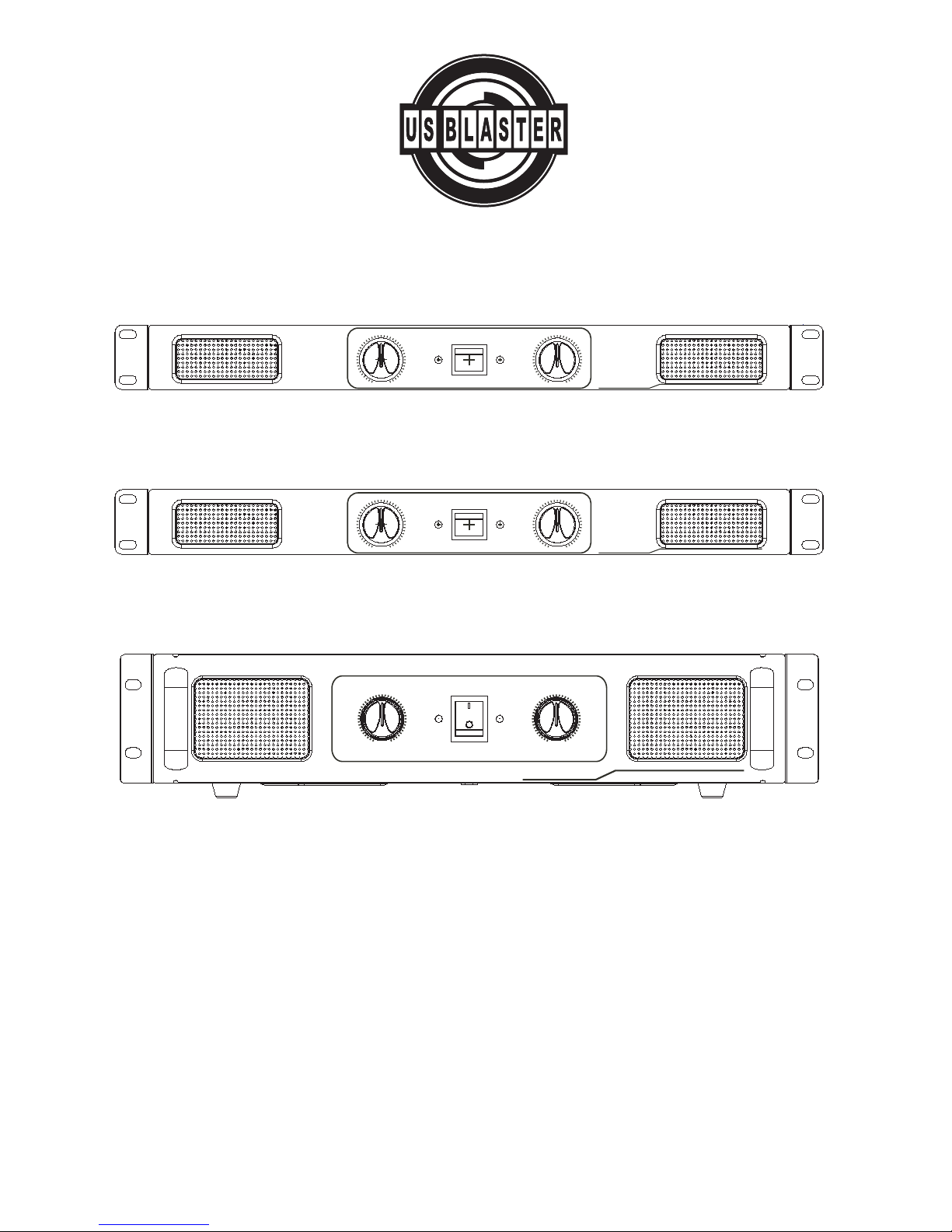
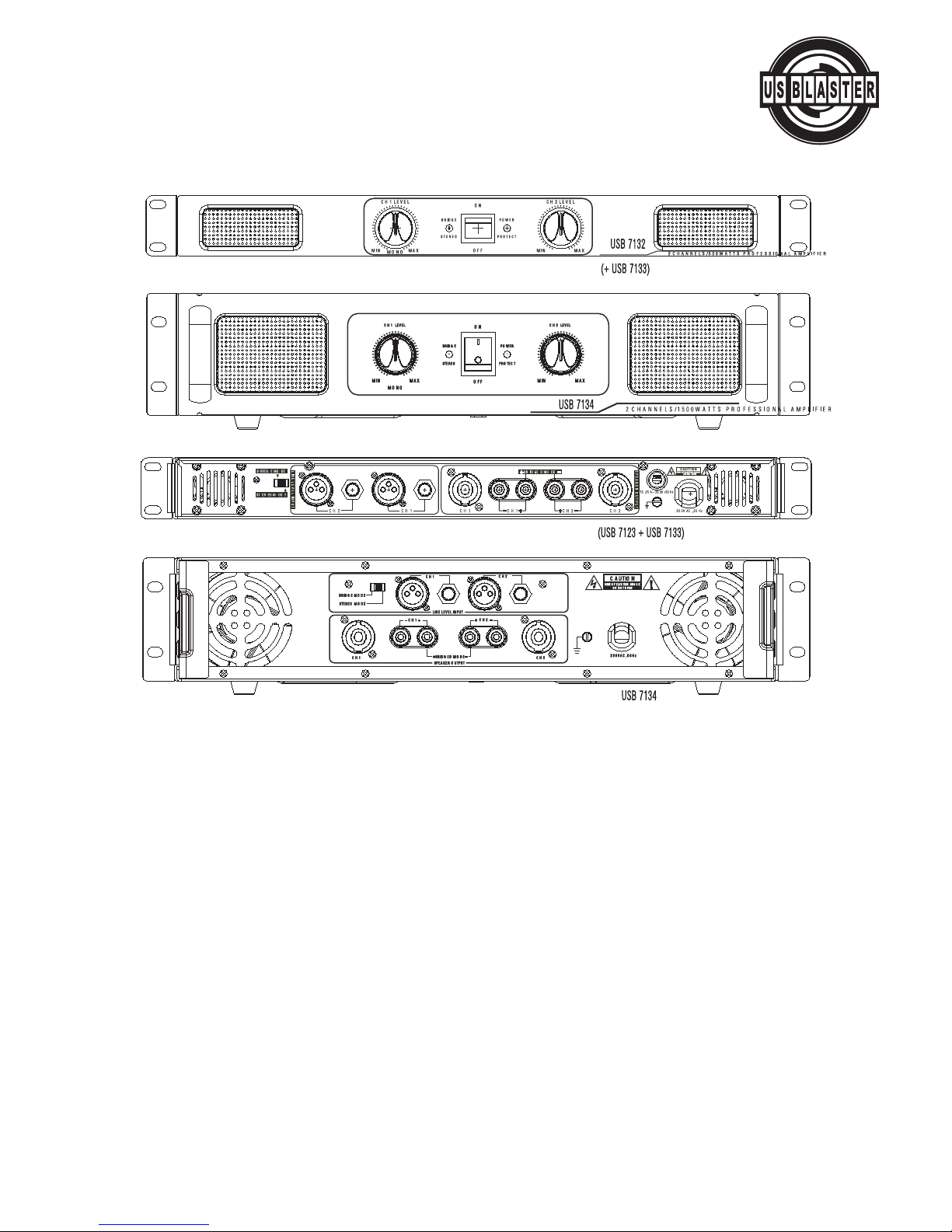
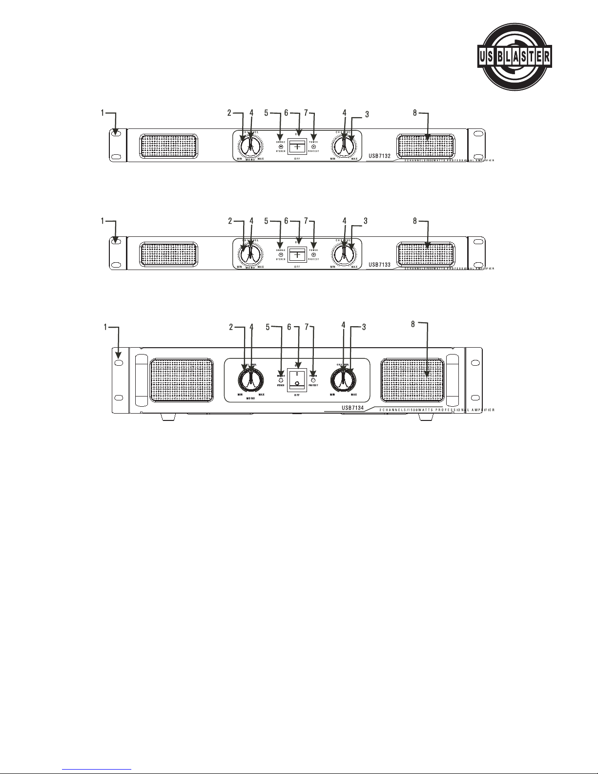
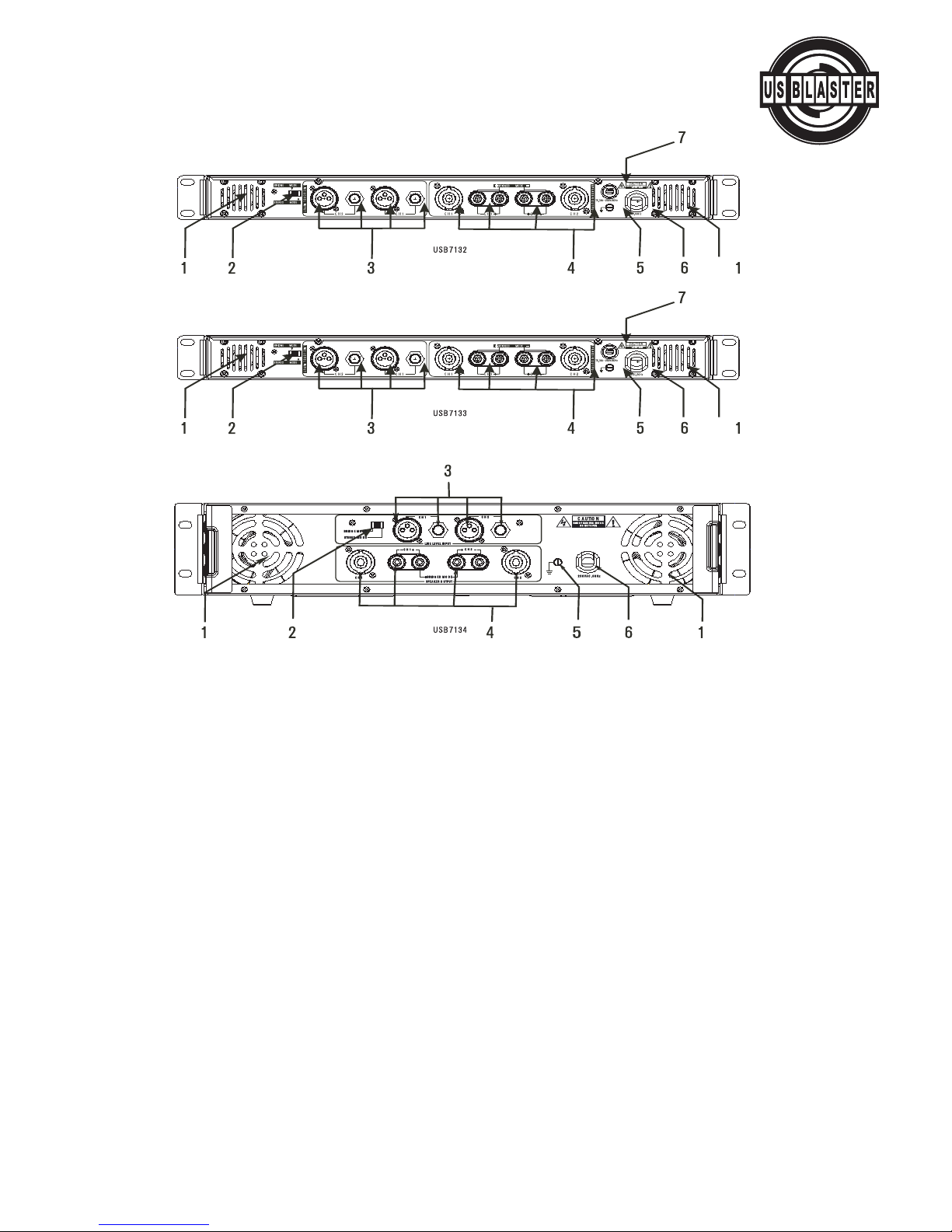
USB 7132 / 7133 / 7134
Professional Power Amplifier
MOUNTING
Mounting & unit dimensions
brackets and rear mounting plates must be fitted. These are available from your dealer. Damage
caused by insufficient support is not covered by the warranty.
To prevent damage to the front panel finish, always use protective plastic cups or washers underne-
ath the rack mounting bolts.
Ventilation gaps between units are not required, however care must be taken to ensure that an
unobstructed free flow of clean air is possible from the back of the unit to the front. It is important
that neither the rear air intakes or front exhaust grilles are covered. The internal airflow of all PA
series amplifiers is designed to minimize contamination of the electronics by the cooling air so fan
filters will not normally be required. If however, the amplifier is to be used in an environment
where the intake air might be excessively dirty, optional external fan filters should be purchased
from your dealer. Fan filters should NOT be fitted unless there is likely to be a problem as they
require regular cleaning to stop them getting clogged. Clogged fan filters will result in the amplifier
going into premature temperature protect.
PLEASE NOTE: Users must ensure that glycol based smoke and related substances are not allowed
to enter the amplifier. Glycol based smoke is HIGHLY corrosive and prolonged exposure will cause
irreparable damage to your amplifier.
Do not expose the amplifier to rain or moisture during either operation or storage. If the unit does
come into contact with moisture, remove the AC power cord immediately and leave it in a suitably
dry, warm place to dry out.
Be aware that when any equipment is taken from a cold location into a hot humid one, condensati-
on may occur inside. Always allow time for the equipment to attain the same temperature as its
environment before applying the AC power cord.
© US Blaster Europe BV
Dimension: 482.5mm(19.0 inch)
wide (Including mounting ear),
44mm(1.7 inch)high for USB
7132/7133, 88.8mm(3.5 inch)
high for USB 7134 487.7mm (19.2
inch) deep(for USB
7132/7133/7134 Including protru-
ding adjusting knob & rear hook-
up).