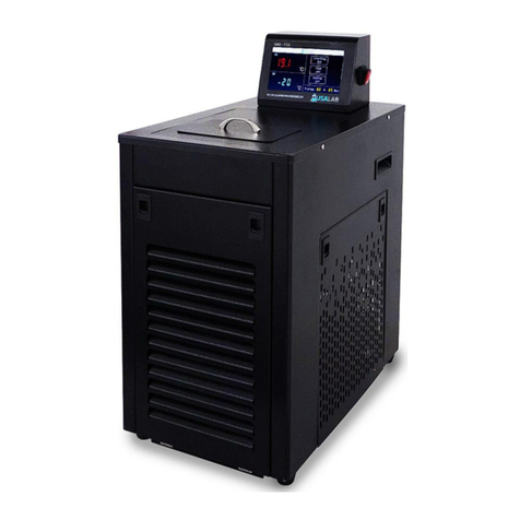
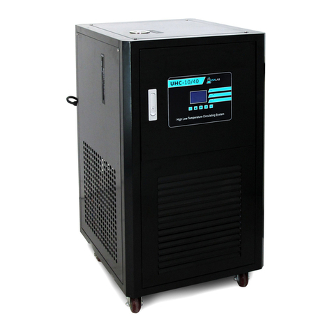
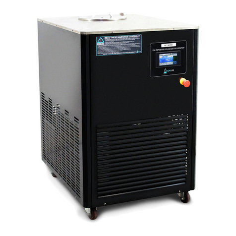
USA Lab CLC Series User manual

Recirculating Closed Loop PLC Chiller Manual
Model: CLC Series with PLC Control
60/80, 100/40, 100/80, 200/40, 200/80

2
Index
Safety Precautions and Explanations
1. Important Information
1.1 Safety Notices
1.2 Features
1.3 Technical Parameters
2. Diagrams
3. Control Panel Operation
3.1 HMI Display Operation
4. Installation
4.1 Included Items
4.2 Thermal Transfer Fluids
4.3 Tubing Connections
4.4 Electrical Connection
4.5 Operating Area
4.6 Operating Instructions and Notes
5. Maintenance
5.1 Periodic Maintenance
5.2 Long Term Storage
6. Technical Diagrams and Troubleshooting
6.1 Circuit Board Diagrams
6.2 Troubleshooting
7. Warranty Information and Coverages
7.1 Warranty
7.2 Return Policy
7.3 Notes

3
Safety Precautions and Explanations
At USA Lab, safety is our number one priority. The following information provides
guidelines for safety when using USA Lab equipment. Any piece of machinery can
become dangerous to personnel when improperly operated or poorly maintained. ALL
employees operating and maintaining USA Lab equipment should be familiar with its
operation, thoroughly trained, and Instructed on the best safety practices. Most
industry accidents are preventable through safety awareness.
Training
It is the responsibility of the customer to ensure that all personnel who will be expected
to operate or maintain the equipment. Participate in training and instruction sessions to
become trained operators. All personnel operating, inspecting, servicing, or cleaning
this equipment must be properly trained in the operation and machine safety. BEFORE
operating this equipment, read the operating instructions in this equipment manual.
Become thoroughly familiar with the machinery and its controls.

4
Safety
•Ensure that all power sources are turned off when the machine is not in use. This encompasses electrical and
pneumatic power.
•Read the manual for any special operational instructions for each piece of equipment. All USA Lab authored
manuals are typically included with each device as well as posted online.
•Know how the equipment functions and understand the operating and halting processes.
•Wear the appropriate personal protective equipment for the task.
•When working on or around all equipment, avoid wearing loose clothing, jewelry, unrestrained long hair, loose
ties, belts, scarves, or articles that may be caught in moving parts. Keep all extremities away from moving parts.
Entanglement can cause death or severe injury.
•For new equipment, check input voltage and compare with the equipment voltage rating. DO NOT supply the
incorrect power to any equipment for any reason whatsoever. Electrical specifications for your machine are
printed on the machine tag. A properly grounded receptacle is required for safe operation regardless of voltage
requirements.
•Use this equipment only for its intended purpose.
•Keep the equipment operating zone free of obstacles that could cause a person to trip or fall toward an operating
machine. Keep fingers, hands, or any part of the body out of the machine and away from moving parts when the
machine is operating.
•Any machine with moving parts and/or electrical components can be potentially dangerous no matter how many
safety features it contains. Stay alert and think clearly while operating or servicing the equipment. Be aware of
operations and personnel in your surroundings. Be attentive to indicator lights, warning lights, and/or operator
interface screens displayed on the machine and know how to respond.
•Do not operate machinery if you are fatigued, emotionally distressed, or under the influence of drugs or alcohol.
•Know where the FIRST AID SAFETY STATION is located.
•Know where the FIRE EXTINGUISHING EQUIPMENT is located.
•Never sit or stand on the machine or on anything that might cause you to fall against the machine.
•Rotating and moving parts are dangerous. Keep clear of the operating area. Never put any foreign object into the
operating area.
•Use proper lifting and transporting devices for heavy equipment. Some types of equipment can be extremely
heavy. An appropriate lifting device should be used.
•Use caution when moving portable equipment. In some cases, the machinery can be heavy and/or may be top
heavy. Portable equipment can gain momentum during transporting and must always be controlled.

5
Symbols and Warnings
Below are examples of commonly used symbols and what they mean.
Understand them and their potential consequences.

6
Section 1 | Important Information
1.1 Safety Notices
USE ETHANOL or DYNALENE XLT 2 (XLT 120)
* USA Lab is not responsible for any loss or harm incurred by using any transfer fluid *
(See section 4.2)
The use of Personal Protection Equipment (PPE) is REQUIRED.
Follow all federal, state, and municipal laws, codes, and ordinances.
Please make sure the power connection is correct and well-grounded. (See section 1.3)
Fluid lines should be unobstructed without any hard bends in the run.
Apply a rag to wipe the parts clean after washing away stains; do not use hard objects.
Do not use near sources of heat or open flames.
Do not run the liquid pump dry, allow plenty of time to prime the pump.
The compressor imposes a 5-minute cool down before it will start. After each power cycle.
Do not allow the compressor to cycle more than 5 times per day.
Do not unplug the unit while it is running.
Install the equipment in a climate-controlled facility ONLY. (60°F to 80°F)
Never use a generator to power this equipment.
Do not change the length of the power cable.
Repairs must be made by USA Lab or by instruction from USA Lab.
If there is a problem, do not continue to use the chiller.
Contact us immediately.
Open Hours:
By Phone: (734) 855-4890 Ask to speak with a technician.
After-Hours:
By Email: Support@usalab.com

7
1.2 Features
•The CLC Series of high-performance closed loop recirculating chillers, use UL Listed phase
change compressors. Danfoss, Panasonic, & Invotech.
•UL Listed circulation pump. (Except 60/80)
•Refrigerant gauges quickly help determine how well the system is operating.
•The pump can move your transfer fluid quickly, up to 315L/Min.
•Flow through plate heat exchanger helps rapidly cool your process fluid.
•Casters make moving around these large chillers a breeze.
•External probe for targeted cooling.
•The included insulated silicone hoses remain flexible at lower temperatures. (60/80 only)
•Clear and easy to read display.
•2”Tri-Clamp adapters included. (100/40, 100/80, 200/40, 200/80 only)
•Siemens Touchscreen HMI (Human Machine Interface).
•PLC automated control or manual control.
CLC model number breakdown:
CLC-XX/XX-PLC = Jacket Liter Cooling Capacity / Lowest Rated Set Point

8
1.3 Technical Parameters
Model Specifications:
Model
60/80
100/40
1
Expansion Tank Capacity
32L
32L
2
Tank Dimensions
15.75" X 7.9" X 15.75"
15.74" X 7.9" X 15.75"
3
Temperature Range
Room Temperature to -80°C
Room Temperature to -40°C
4
Cooling Capacity
22kW @22°C to 368W @-80°C
22kW @22°C to 368W @-40°C
5
Exchanger Surface Area
1.46m² x 2
2.50m² x 1
6
Temperature Accuracy
+/- 0.5°C
+/- 0.5°C
7
Power Requirements
220V to 240V 60Hz 1PH
208V to 230V 60Hz 3PH
8
Amperage
37A - Hardwire Only
21A - Hardwire Only
9
Circulating Pump Wattage
370W x 1
750W x 1 (UL)
10
Condenser Fan Wattage
280W x 1 | 185W x 1
280W x 2
11
Compressor Type
Scroll | 5HP Invotech x 2 (UL)
Scroll | 10HP Danfoss x 1 (UL)
12
Control Type
Siemens PLC w/ Ext. Probe
13
Pump Flow Rate
11 gpm (42L/Min)
35.7 gpm (135L/Min)
14
Pump Lift / Head
91 ft. (28m)
82 ft. (25m)
15
Pump Pressure
40.6 psi (2.8bar)
36.3 psi (2.5bar)
16
Inlet / Outlet Fitting Size
3/4" MNPT
1.5" FNPT or 2" Tri-Clamp
17
Refrigerant
R-404A STG 1 | R-23 STG 2
R-404A
18
External Dimensions
43.3" X 33.3" X 51.2"
43.3" X 31.4" X 51.2"
19
Weight
514 lbs.
430 lbs.
100/80
200/40
200/80
1
32L
70L
230L
2
15.74" X 7.9" X 15.75"
19.7" X 13.8" X 15.8"
53.2" X 13.8" X 19.7"
3
Room Temperature to -80°C
Room Temperature to -40°C
Room Temperature to -80°C
4
44kW @22°C to 735W @-80°C
27.5kW @22°C to 460W @-40°C
44kW @22°C to 735W @-80°C
5
2.50m² x 2
4.06m² x 1
2.50m² x 2
6
+/- 0.5°C
+/- 0.5°C
+/- 0.5°C
7
208V to 230V 60Hz 3PH
8
41A - Hardwire Only
31A - Hardwire Only
48A - Hardwire Only
9
1.5kW x 1 (UL)
3kW x 1 (UL)
2.2kW x 1 (UL)
10
280W x 3
280W x 2
280W x 4
11
Scroll | 10HP Danfoss x 2 (UL)
Scroll | 12.5HP Panasonic (UL)
Scroll | 10HP Danfoss x 2 (UL)
12
Siemens PLC w/ Ext. Probe
13
62 gpm (235L/Min)
79.3 gpm (300L/Min)
83.2 gpm (315L/Min)
14
78 ft. (24m)
131.2 ft. (40m)
98.4 ft. (30m)
15
34.8 psi (2.4bar)
58 psi (4bar)
43.5 psi (3bar)
16
1.5" FNPT or 2" Tri-Clamp
17
R-404A STG 1 | R-23 STG 2
R-404A
R-404A STG 1 | R-23 STG 2
18
58.7" X 31.5" X 56.7"
51.6" X 35.4" X 59.5"
58.7" X 37.0" X 64.6"
19
860 lbs.
1144 lbs.
948 lbs.

9
Section 2 | Diagrams
Pump Graphs
60/80: Not Available
100/40:
100/80:
200/40:
200/80:

10
Section 3 | Control Panel Operation
3.1 HMI Display Operation
Disclaimer –Parameters are not allowed to be modified by end users. This is to protect the equipment from
accidental damage. Modifying parameters for any reason, without our knowledge and permission will
constitute a void of the warranty.
The PLC display is laid out in the simplest way possible. This section will focus on the different functions of the
PLC interface and how they are used. Including how to edit, save, and reload recipes.
Many buttons on the main display will change color or text when pressed.
The following image shows the different sections of the display.
If you have any questions or concerns on using the display, please contact us.

11
Operation Page:
** Be careful not to set an ON time for the machine to run while unattended **
1. Point Value is the current transfer fluid temperature.
2. Set Value is the desired transfer fluid temperature.
3. You can select the desired measurement probe by pressing #3.
“Outlet temp control”uses the internal fluid line probe for temperature regulation.
“External temp control”uses the external probe for temperature regulation.
4. Loop Control button –This button turns the fluid pump on or off.
5. Cooling Control button & Compressor Indicators –This button turns cooling on or off.
Snowflake Indicator #1 –Stage 1 Enabled
Snowflake Indicator #2 –Stage 2 Enabled (only on -80°C models)
6. Control Style - Manual Control or Automated Control (Recipe Enabled)
7. Automated Control - This area displays the recipe #, name, and what phase the recipe is on. The
“Progress”button advances to the next phase without completing the current phase.
8. Turn-On / Shutdown Timer –This is a timer to turn on or off the system after the set time.
9. Curve - This button will take you to the Graph Page where it shows you the temperature over time. This
function is not persistent, all data will be cleared when navigating away from this page.
10. Recipe - This button will take you to the recipe programming page. This is where you make your recipe
for automated control of the chiller.

12
Recipe Page:
This is the Recipe Page. You can have a maximum of 15 phases in each recipe. Enter a value of “0” to ignore that
phase. You can save and open your recipes by using the box outlined above. Up to 70 recipes can be stored.
To Program a Recipe:
1. Press the temperature box and edit the temperature you would like for each phase.
2. Press the time box edit the time you would like for each phase.
3. Press Save to make the change permanent.
4. When finished changing the recipe, press Apply.
5. Press Return to go back to the Operations Page.
Name and save a Recipe:
1. Press the box next to the word “Number:”then edit your recipe number.
2. Press the box next to your recipe number, then name your recipe.
3. Press Save to make sure all settings are saved.
4. Press Upload to save the recipe in memory.
5. If you wish to apply it after creating, press Apply.
Load a Recipe:
1. Press the box next to the word “Number:”then enter your saved recipe number.
2. Press the Upload button to pull the recipe from memory.
3. The name of your recipe should appear in the name field.
4. Press Apply to make the recipe active.

13
Section 4 | Installation
4.1 Included Items
Each chiller includes the following:
(Except 60/80, ¾” NPT fittings and no gaskets or clamps)
2 x 6ft. of insulated flexible bellow hose with 2”Tri-clamp ends. 12ft. of tubing total.
1 x Manual Pouch with PTFE thread tape and external probe. (not pictured below)
2 x 2”Tri-clamp gasket
2 x 2”Tri-clamp clamp
2 x 1.5”MNPT to 2”Tri-clamp adapter
1 x 1.5”MNPT to 1.5”MNPT
1 x 1.5”MNPT ball valve
If you are missing any items, contact us.

14
4.2 Thermal Transfer Fluids
Recommended: Ethanol* or Dynalene XLT 2 (Formerly XLT 120)
*If local laws and ordinances allow.
Do Not Use Automotive Anti-freeze, it Contains Additives That Have Been Known To Corrode Heat Exchangers.
Do Not Use Tap Water, as it Can Cause Rusting of Many Internal Parts.
Failure to follow these warnings will result in damage to the equipment and void the warranty.
* USA Lab is not responsible for any loss or harm incurred by using any transfer fluid *
4.3 Tubing Connections
Precautions:
Fluid lines should be unobstructed without any hard bends in the run.
Support the weight of the lines accordingly.
Install the ball valve at the outlet port.
Tubing insulation is pre-installed.
Connect the inlet to the lowest point, and the outlet to the highest point of the chiller.
If additional tubing length is needed. You must insulate the tubing or performance loss will occur.
Insulate any exposed jackets or performance loss will occur.
Do not restrict the flow without using a bypass. Loss of performance will occur.
PTFE gaskets will require high pressure tri-clamps to work properly.
(we will replace PTFE gaskets with Buna gaskets, contact us if you have received PTFE)
Fittings Installation:
Before installing adapters and fittings. Verify all included parts have been received. Begin by wrapping the end
of the NPT threads with PTFE tape. Tape the end of the fitting (green) not in the center (red). Thread tape
allows the male fitting to slip further into the female fitting. Sealing the combination. Wrap 4-5 times per fitting

15
Outlet Connection (Top):
Inlet Connection (Bottom):

16
4.4 Electrical Connections
Each unit has its own power requirements, please understand their differences. This unit must be operated on
its own circuit Installed by a licensed professional. DO NOT attempt to replace/extend the power cord of the
unit. Failure and injury will result.
All units must be hardwired into a general duty safety switch or a lockout:
Chiller compressor starting amperage calculation: Nominal amperage + 25%
Example. 41A x 1.25 = 51.25A required
Wire gauge / Max. Ampacity (@75C)
10 Gauge | 35A
8 Gauge | 50A
6 Gauge | 65A
4 Gauge | 85A
-80°C units use a temperature delay for the second compressor. That way failures are not caused by higher-
than-expected amperages.

17
4.5 Operating Area
Always leave at least 24-36 inches around the unit. Obstructing the ventilation will cause poor performance or
part failure.
Always keep the operating area clean and organized to prevent injury or damage.
Only operate the unit in a climate-controlled facility. Normal operating temperature is 70°F or 20°C. If the
temperature exceeds 90°F or 32°C performance will be degraded.
Do not operate in high particulate areas, such as biomass grinding rooms. Damages will not be covered.
In areas with high humidity, performance will be degraded. Use air conditioning to reduce the humidity.
Units returned that have signs of outside use. Will automatically be determined to be improperly used and
cared for. Outdoor operation will void the warranty.
4.6 Operating Instructions and Notes
Filling and Priming:
Connect your tubing and prepare to inspect for leaks. Use a helper to turn on and off the loop when leaks are
detected. Keep empty buckets and spill absorption material close by in case of an accident. Wear appropriate
clothing and PPE. To make this process quicker, pre-fill your jacket after connecting the chiller.
1. Power on the unit, but do not enable any functions yet.
2. Plug in the external probe. (Required for unit to function)
3. Open the top fill port.
4. Place a funnel into the fill port.
5. Begin filling with your transfer fluid.
6. Fill the tank to 60% of the way up the level sight glass
7. Stop filling, then enable the loop. * Look for leaks *
8. When the level drops to 20% of the way up the glass, stop the loop.
9. Repeat until the level has stopped dropping.
10. Only fill the tank up 50-60% when you have finished priming.
Before operating the unit each time. Inspect the system for breaks, leaks, and signs of wear.
Operating steps:
• Power on the unit.
• Open the ball valve.
• Set the target temperature or select the recipe you wish to use and apply it.
• Run the loop.
• Enable cooling.
• Run until the process is complete.
• Then close the ball valve and shut off the chiller.
If you have any questions on how to operate the unit further, contact the technical department.

18
Section 5 | Maintenance
5.1 Periodic Maintenance
Shut off the breaker AND disconnect the power cord before any maintenance
Use a damp soft cloth to wipe clean. Stubborn stains should be cleaned by neutral detergents.
The maintenance of internal electrical and cooling parts must be performed by professionals or trained
electricians.
Do not directly splash water over the product or use abrasive powder, diluent, oil, kerosene, acidic material,
and similar substances during cleaning, or else shock or other accidents will occur.
Fluid:
Ethanol will evaporate over time. Check and refill periodically.
Condenser:
Check and clean the condenser regularly. Every quarter for low dust facilities, or every month for high dust
facilities.
Unit:
Check the unit over monthly for leaks, broken glass, melting, burning, or any other damages.
Please bring any concerns to our attention immediately.
Gauges:
Check the refrigerant gauges regularly. If a loss of pressure is noticed. Stop using the unit immediately. Take
the unit out of commission until it can be repaired. Contact us.
5.2 Long Term Storage
Empty the unit of fluid.
Cap the inlet and outlet.
Clean the condenser.
Clean the body of the unit.
Wrap the unit with shrink wrap plastic.
Store in a secure level location.
Block the casters from rolling.

19
Section 6 | Technical Diagrams and Troubleshooting
6.1 Circuit Board Diagrams
- Reserved for future revision -

20
6.2 Troubleshooting
Problem
Cause
Solution
No power
A. Phase protection shutdown.
B. No power from panel.
C. Panel has power, chiller does
not.
D. 240V 3 phase power.
A. Move high leg to L3.
(Except 60/80)
B. Reset breaker or check fuses.
C. Check breaker on the chiller.
D. Contact us to adjust input
voltage.
Temperature display is incorrect
A. Probe wire is loose.
B. Temperature probe has failed.
C. RTD signal converter is bad.
A. Tighten the loose probe wire.
B. Replace the probe.
C. Replace the signal converter.
Display is not working correctly
A. Bad 24V DC power supply.
B. Unplugged 24V plug to display.
C. External probe is not
connected.
D. Data cable damaged or
unplugged.
A. Replace 24V DC power
supply.
B. Re-seat 24V plug into display.
C. Plug-in external probe.
D. Replace or plug-in data cable.
Shock from the shell of the unit
A. System not grounded.
B. Damaged component causing
fault.
A. Properly connect a ground.
B. Replace damaged
component.
This manual suits for next models
5
Table of contents
Other USA Lab Chiller manuals
Popular Chiller manuals by other brands

Emerson
Emerson Liebert DM Chilled Water Series user manual

Modena
Modena CC 3180 User manual book

Daikin
Daikin EWWD170~600G-SS Installation, operation and maintenance manual

York
York YVAM INSTALLATION PROCEDURE

Carrier
Carrier 30GX Series Installation, operation and maintenance instructions

Polar Refrigeration
Polar Refrigeration CB929 instruction manual

SMC Networks
SMC Networks HRS200-A 46 S Series Operation manual

Quantech
Quantech QTC2015T manual

KKT
KKT Compact-Line cBoxX 30 operating instructions

York
York YCAL0080SC Installation operation & maintenance

Daikin
Daikin EWAH TZ D Series Installation, operation and maintenance manual

York
York UL R134A user manual