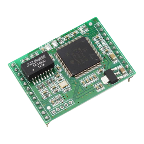
USR IOT USR-TCP232-T2 User manual

USR-TCP232-T2 user manual www.usriot.com
Jinan USR IOT Technology Limited www.usriot.com
2
Contents
USR-TCP232-T2 User Manual......................................................................................................................................................1
1. Quick Start...............................................................................................................................................................................4
1.1. Hardware Testing Environment....................................................................................................................................4
1.2. Connection...................................................................................................................................................................4
1.3. Default parameter........................................................................................................................................................6
1.4. Data transport test....................................................................................................................................................... 7
2. Overview................................................................................................................................................................................. 8
2.1. Brief Introduction.........................................................................................................................................................8
2.2. Features........................................................................................................................................................................8
2.3. Basic parameters..........................................................................................................................................................9
3. Hardware parameter.............................................................................................................................................................10
3.1. Pin define................................................................................................................................................................... 10
3.1.1. Pin Definition.................................................................................................................................................. 10
3.1.2. Dimension.......................................................................................................................................................12
3.1.3. Evaluation Kit.................................................................................................................................................. 12
3.2. Hardware Reference Design...................................................................................................................................... 14
3.2.1. Typical Application Connection.......................................................................................................................14
3.2.2. Power Interface...............................................................................................................................................14
3.2.3. UART Interface................................................................................................................................................15
4. Module function................................................................................................................................................................... 15
4.1. Network basic function..............................................................................................................................................16
4.1.1. IP address/ subnet masks/gateway.................................................................................................................16
4.1.2. Web server......................................................................................................................................................17
4.1.3. Firmware upgrade in webpage....................................................................................................................... 18
4.2. Socket function.......................................................................................................................................................... 18
4.2.1. TCP Client........................................................................................................................................................19
4.2.2. TCP Server.......................................................................................................................................................21
4.2.3. UDP Client.......................................................................................................................................................22
4.2.4. UDP Server......................................................................................................................................................23
4.2.5. Httpd Client.....................................................................................................................................................24
4.2.6. TCP and UDP mechanism................................................................................................................................26
4.3. DHCP and DNS Function............................................................................................................................................ 26
4.4. VCOM.........................................................................................................................................................................28
4.4.1. Module Work as Client................................................................................................................................... 28
4.4.2. Module Work as Server.................................................................................................................................. 29
4.4.3. Create VCOM.................................................................................................................................................. 30
4.5. Serial port function.................................................................................................................................................... 31
4.5.1. Basic parameters............................................................................................................................................ 31
4.5.2. Serial port framing..........................................................................................................................................32
USR-TCP232-T2 user manual www.usriot.com
Jinan USR IOT Technology Limited www.usriot.com
3
4.5.3. RFC2217..........................................................................................................................................................32
4.6. Special function......................................................................................................................................................... 33
4.6.1. Heartbeat package..........................................................................................................................................33
4.6.2. Registration package.......................................................................................................................................33
4.6.3. USR-cloud....................................................................................................................................................... 34
4.6.4. Customize webpage........................................................................................................................................36
4.6.5. Link..................................................................................................................................................................37
4.6.6. Reset............................................................................................................................................................... 37
4.6.7. Index............................................................................................................................................................... 37
4.6.8. The number of the connected client.............................................................................................................. 37
4.6.9. State................................................................................................................................................................38
4.6.10. Short connection.......................................................................................................................................... 38
4.6.11. Clear buffer data........................................................................................................................................... 39
4.6.12. Restore out time........................................................................................................................................... 39
5. Parameter setting..................................................................................................................................................................40
5.1. Network protocol setting parameter.........................................................................................................................40
5.1.1. Setting software setting parameter................................................................................................................40
5.1.2. Protocol configuring to setting parameters....................................................................................................46
5.2. Webpage setting parameters.....................................................................................................................................46
5.2.3. Serial port....................................................................................................................................................... 49
5.3. AT comment...............................................................................................................................................................52
5.3.1. AT command overview............................................................................................................................................52
5.3.2. AT command error code................................................................................................................................. 53
5.3.3. AT command................................................................................................................................................... 53
5.3.4. AT command................................................................................................................................................... 54
6.Contact us.............................................................................................................................................................................. 67
7.Disclaimer.............................................................................................................................................................................. 67

USR-TCP232-T2 user manual www.usriot.com
Jinan USR IOT Technology Limited www.usriot.com
4
1. Quick Start
USR-TCP232-T2 is used for data bidirectional transparent transmission between TTL and Ethernet. T2 module itself
complete protocol conversion, parameter can be set by built-in webpage or software. Once set permanent preservation.
This chapter is quick start for using USR-TCP232-T2 module,we advice users to read it carefully and operate personally,
it can help you know about module generally.
Here is application case for inference:
http://www.usriot.com/support/application-case/usr-tcp232-series-application-case/
You can also email it to Customer Support Center:
http://h.usriot.com/
1.1. Hardware Testing Environment
To test T2 conversion function, user should connect T2 UART to computer by USB to TTL serial line, then connect T2
LAN port to computer LAN port by internet cable. If you want to use T2 evaluation board, use USB to RT232 serial line
instead of USB to TTL serial line.
Diagram 1.1-1 Hardware Link
Note: The power and cable are from USR.
1.2. Connection
To prevent the thing that occur when the custom use it like can not find server, can not ping and can not open the
webpage. After connect you should check the computer before used.
1) Shut down firewall and antivirus software.

USR-TCP232-T2 user manual www.usriot.com
Jinan USR IOT Technology Limited www.usriot.com
6
3) If you want to connected module to PC directly, user should set static IP for computer which is in the same
network segment with module.
Diagram 1.2-3
1.3.Default parameter
Item
Intro
User name
admin
Password
admin
IP address
192.168.0.7
Subnet masks
255.255.255.0
Default gateway
192.168.0.1
Work mode
TCP client
Target port
8234
Local port
20108
Target IP
192.168.0.201
Serial port baud
115200
Serial parameter
None/8/1
Diagram 1.3-1 T2 Module Default Parameter

USR-TCP232-T2 user manual www.usriot.com
Jinan USR IOT Technology Limited www.usriot.com
7
1.4. Data transport test
Steps for network communication parameters:
1) Install USR-TCP232-Test.exe .
2) Connect UART to PC, LAN to PC.
3) Protocol: TCP Server
Server IP: 192.168.201 ( PC Static IP )
Server Port No: 8234
Baud rate:115200
Serial port parameters: None/8/1
From now, we can perform the send/receive data test. The direction from serial to network is: serial port of PC_> T2
serial port _> T2 ethernet port_>PC. The direction from net work to serial is: PC network _> T2 ethernet port_> T2 serial
port _> serial port of PC
The diagram as below:
Diagram 1.4-1 Port to LAN Test

USR-TCP232-T2 user manual www.usriot.com
Jinan USR IOT Technology Limited www.usriot.com
8
2. Overview
2.1. Brief Introduction
USR-TCP232-T2 is TTL to Ethernet module, which can realize the bi-direct data transparent transmission between RJ45
port and TTL serial port. It can be applied to interface 232 and 485 by level conversion circuit.
Equipped with Cortex-M0 core, fast speed and high efficiency. Support several function meet more need.
T2 module is easy to operate and has strong compatibility.On the basis of adding new functions, it is compatible with
the setting protocol of T24 series to provide convenience for old users.At the same time, a setting protocol similar to M4 is
added. For customers who adopt other series of products, it can be applied to T2 only by simple adjustment.
2.2. Features
10/100Mbps can adopted to Ethernet, support AUTO-MDIX switching of network cablle crossovers.
Work mode:TCP server, TCP client, UDP server, UDP client, Httpd client.
Baud of the serial port can edit from 600bps to 460.8Kbps. Support five ways to check including None, Odd, Eben,
Mark, Space.
Customize heartbeat package, keep the connection real and reliable, no crash.
Customize registration package, check the connection status, and also customize the head of package,choose the
MAC address to be the registration package.
In TCP Server mode, the number of client connected can be modify from 1 to 16, default is 4. The IP of connected
client can be see. Send and receive data according to connection calculation.
In TCP Server mode, when the client number reach the max number, the new client can instead of the old one or not
can be set.
Support webpage,AT command, serial port protocol,webpage setting parameter,setting protocol. Provide custom to
use in their own software.
Support TCP client short connection, the time can be set.
Support reset out time, the time can be set.
Before the TCP connect, whether clear the data before can be set.
Support DHCP, get IP automatically
The unique MAC address in the world, and the address can be modify. Support the function of customize MAC.
Support DNS, domain name resolution.
Support customize the address of DNS server.
Support upgrade the firmware from webpage, more convenient.
Support v-com
Support across the gateway, switching and router
Support work in LAN, also can access the external.

USR-TCP232-T2 user manual www.usriot.com
Jinan USR IOT Technology Limited www.usriot.com
9
2.3. Basic parameters
Hardware parameters
Work voltage
VCC: DC 3.3V, 3.15V~3.45 V
VDD: DC 5V, 4.75V~5.5V
Run current
150mA@5V/3.3V
LAN port
RJ45 with electromagnetism isolation
Serial baud rate
600-460.8K(bps)
Serial standard
TTL-3.3V
Software parameters
Network protocol
IP, TCP/UDP, ARP, ICMP, IPV4
Method of IP access
Static IP, DHCP
Domain name solution
Support
User setting
Software setting, webpage setting, AT command setting
Simple transparent transport
TCP server /TCP client/ UDP server / UDP client
RFC2217
Support
Httpd client
Support
TCP server
Max number of connected TCP is 16(can customize)
Network cache
Send: 6Kbyte; receive: 4Kbyte
Serial cache
Receive:800byte
Average transport delay
<10ms
Set of software
V-COM; USR- cloud; parameter setting
Packaging mechanism
4 byte packaging time; 400 byte packaging length
Others
Certification
CE, FCC
Size
50.5*22.6*15.0 mm (L*W*H)
Temperature
Working temp: -25 ~ 75 °C
Storage temp: -40 ~ 105 °C
Storage humidity: 5% ~ 95% RH
Packaging
Electrostatic bubble
Diagram 2.3-1 USR-TCP232-T2 Parameters

USR-TCP232-T2 user manual www.usriot.com
Jinan USR IOT Technology Limited www.usriot.com
10
3. Hardware parameter
3.1. Pin define
3.1.1. Pin Definition
Diagram 3.1.1-1 T2 Interface Definition
NO
Pin
Function
Instr
1
VDD
Power
Power: 5V@200mA
2
VCC
Power
Power: 3.3V@200mA
3
GND
Ground location
Grounding
4
RST
Reset
Pin receive current below 200ms ,it can reset
module. If unneeded, don’t connect the pin .
(Power on , reset means restart the module)
5
TXD
Send data
TTL connect to 3.3v MCU
(For 5V, refer to Diagram 3.1.1-2)
6
RXD
Receive data
TTL connect to 3.3v MUC
(For 5V, refer to Diagram 3.1.1-2)
7
CFG
(reload)
Pin for module
configuration and
restore
factory default
When normal working , don’t connect the pin or
connect to high level. Under low level, the pin is
used for module configuration, access to power
then pull down“Reload” pin
Refer to 4.4.3 Factory Reset
Form 3.1.1-1 T2 Pin Definition

USR-TCP232-T2 user manual www.usriot.com
Jinan USR IOT Technology Limited www.usriot.com
11
Diagram 3.1.1-2 3.3V to 5V voltage conversion circuit
Diagram 3.1.1-3 Reserved Pin
1
485-en
Reserve pin
RS485 enable pin
2
Link
Reserve pin
Used as indication pin for TCP connection status.
Refer to 4.4.2 Link Function
3
ISP
Reserve pin
Hasn’t use
Form 3.1.1-2 T2 Reserved Pin Definition

USR-TCP232-T2 user manual www.usriot.com
Jinan USR IOT Technology Limited www.usriot.com
14
3.2. Hardware Reference Design
3.2.1. Typical Application Connection
Diagram 3.2.1-1 Typical Application Connection
Note:
1) RST: Restart button. It works at low level, 3.3V, 10K pull-up resistor inside. When it access to power or
breakdown, pull down 300ms then high level.
2) Link: connection indication.Can be used as indication pin for net connection, when connected, it outputs low
level; When unconnected, it output high level.
3) CFG(Reload): connect to external button or configuration pin. 3.3V, 10K pull-up resistor inside. Press it
and pull to low level, then release hands after 3 seconds, module restores factory default and restart.
4) UART_TXD/RXD: data rend/ receive signal(10K pull-up resistor inside)
3.2.2. Power Interface
USR-TCP232-T2 has dual power supply interface, 5.5 v and 3.3 v (only choose one) Working current 150 mA, max
current 200mA .
VCC: typical value DC 3.3V, 3.15V~3.45 V. It is used for 3.3 V MCU.
VDD: typical value DC 5V, 4.75V~5.5V. When connect to 5V MUC, refer to Diagram 3.2.3 -2 3.3V to 5V voltage
conversion circuit

USR-TCP232-T2 user manual www.usriot.com
Jinan USR IOT Technology Limited www.usriot.com
15
3.2.3. UART Interface
UART can connect RS232 chip, UART has TXD/RXD signal wire. Take RS232 Level for example.
Diagram 3.2.3-1 UART Interface Design
If communicated with MCU (3.3V TTL), connect module’s TXD to MCU’S RXD, modules’ RXD to MCU’S TXD. If MCU 5V
TTL, need voltage conversion circuit, as follows:
Diagram 3.2.3-2 UART Level Switch Design
4. Module function
Here are the function of T2, below is the overall block diagram.

USR-TCP232-T2 user manual www.usriot.com
Jinan USR IOT Technology Limited www.usriot.com
16
Diagram 4-1 Module Functions
4.1. Network basic function
4.1.1. IP address/ subnet masks/gateway
1. IP address is the identity representation of the module in the LAN, which is unique in LAN. So it can not be repeated.
There are two ways to access the network: static IP and DHCP.
Static IP
Static IP need to be setting handy. Meanwhile write the IP, subnet masks and modbus gateway. Static IP can be used
in.
Advantage: can be searched when the device accesses the IP that can not distribute.
Disadvantage: can not communicate if the device in the different port of the different LAN
DHCP
Main function is get the IP address, gateway address, DNS server address from the gateway holder, and no need for
the complex steps. Adopted to the situation have little requirement for IP and do not ask the IP to corresponds to module.
Advantage: access the devices that support DHCP server like router can communication directly. Reduce the trouble of
setting IP address gateway and subnet masks.
Disadvantage: directly to the computer in the net do not support the DHCP server, T2 can not work
2. Subnet masks mainly used to determine the host number and the network number, indicates the number of subnet and
determine the flag within the subnet. The subnet masks needed to set,usually we use the subnet masks: 255.255.255.0,
the network number is the former 24, the holder name is the last 8, number of subnet is 255, the module IP is in the range
of 255, and then we are sure that the module IP is in this subnet.
3. Gateway means the net number of the current IP that module in. If connect the device like router when access the
external, the gateway IP is the router IP, if there is some thing wrong with setting, can not access the external net. If no
need to connect the router, keeping default is ok.
4. Reference AT command

USR-TCP232-T2 user manual www.usriot.com
Jinan USR IOT Technology Limited www.usriot.com
17
command name
Instr
AT+WAN
Setting and query the access way of T2 IP, IP/subnet
masks/gateway parameter
Form 4.1.1-1 AT command
5. Software setting:
Diagram 4.1.1-1 Software Setting
4.1.2. Web server
T2 has its own webpage server, same as the normal webpage server, which is convenient for user to setting parameter
and query the status of T2.
The port of webpage can be setting, default is 80.
Steps:
Open the browser, fill the IP of T2, e.g.:192.168.0.7(IP address and PC in the same net.)
Fill the user name and key word in the login webpage, default is admin, click the sure and enter.
Then there is the status webpage:

USR-TCP232-T2 user manual www.usriot.com
Jinan USR IOT Technology Limited www.usriot.com
18
Diagram 4.1.2-1 Webpage
4.1.3. Firmware upgrade in webpage
Webpage upgrade the firmware, stable and simple. Use this new function, meet the custom requirement. If you need
to upgrade, you can query us from the USR support or ask firmware from supply. The way to upgrade please refer the
5.1.1.
4.2. Socket function
The work mode for T2 divide into five: TCP Client、TCP Server、UDP Client、UDP Server、Httpd Client. You can use
webpage and setting software. The page is as fellows:
Diagram 4.2-1 Socket

USR-TCP232-T2 user manual www.usriot.com
Jinan USR IOT Technology Limited www.usriot.com
19
Related AT command
command name
Instr
AT+sock
Setting the work mode/target IP/ target port
Form 4.2-1 socket AT command
4.2.1. TCP Client
It has to be connected before transferring data.
1) In TCP Client Mode,TCP232-T2 connects TCP Server actively, establish a connection to transmit date. According to
the TCP protocol related rule, there difference for TCP client between connect and disconnect, to make sure the data
exchange more stable. Usually used in the data interaction between device and server, which is the most common form of
network communication.
2) In TCP Client Mode, support the function of identifying disconnected link. When connected, it will send keepalive
package every 15s. If unconnected, it can be detected timely and enforce T2 to disconnect the former link to establish a
new one.
3) When TCP232-T2 try to connect remote server, if the local port number is not “0" ,it will establish a connection
with the same source port every time.
4) Support synchronizing baud rate, USR-cloud and short connection function.
5) In a LAN, if the T2 is static IP, please keep T2 IP stay in the same network segment with gateway, and setting the
gateway IP, otherwise can not work as normal.
6) Note: keepalive, synchronizing baud rate and USR-cloud are more on the below.
Other manuals for USR-TCP232-T2
1
Table of contents
Other USR IOT Control Unit manuals

USR IOT
USR IOT USR-C322 User manual

USR IOT
USR IOT USR-ES1 User manual

USR IOT
USR IOT USR-K5 Quick setup guide

USR IOT
USR IOT USR-TCP232-E2 User manual

USR IOT
USR IOT USR-C210 User manual

USR IOT
USR IOT USR-GM3 User manual

USR IOT
USR IOT WH-LTE-7S1-E User manual

USR IOT
USR IOT USR-K7 User manual

USR IOT
USR IOT USR-K3 Setup guide

USR IOT
USR IOT USR-WIFI232-A2 User manual