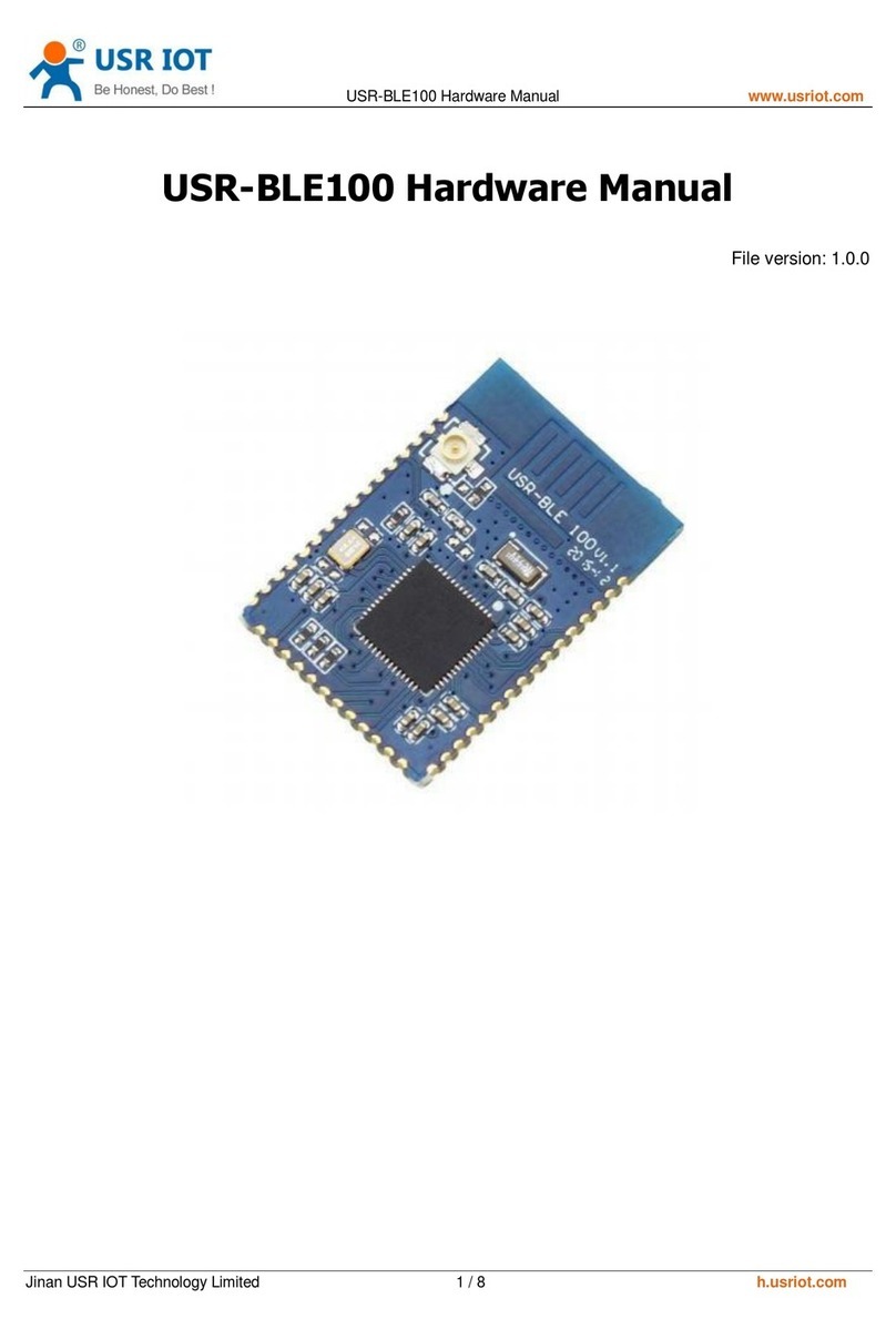
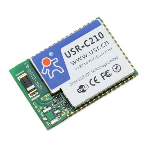
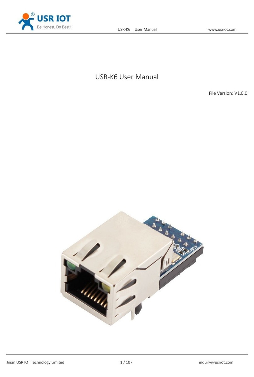
USR IOT WH-LTE-7S1-E User manual

WH-LTE-7S1-E Hardware Manual Technical Support: h.usriot.com
Jinan USR IOT Technology Limited www.pusr.com
2
WH-LTE-7S1-E Hardware Manual.................................................................................................................................. 1
1. Overview..........................................................................................................................................................................3
2. Introduction......................................................................................................................................................................3
2.1. Specifications...................................................................................................................................................... 3
2.2. System Diagram................................................................................................................................................. 4
2.3. Pins Definition..................................................................................................................................................... 5
2.4. Evaluation Board................................................................................................................................................ 6
3. Application Interfaces.................................................................................................................................................... 7
3.1. Power Interface...................................................................................................................................................7
3.2. USB Interface...................................................................................................................................................... 8
3.3. UART Interface....................................................................................................................................................8
3.4. SIM Interface....................................................................................................................................................... 9
3.5. Indicators............................................................................................................................................................11
3.6. Reset/Reload.................................................................................................................................................... 13
3.7. Turn on/off Module Using PWRKEY............................................................................................................. 13
4. Electrical Characteristics............................................................................................................................................ 14
4.1. Operating/Storage Temperature.................................................................................................................... 14
4.2. Power Supply.................................................................................................................................................... 14
4.3. IO Voltage Range............................................................................................................................................. 14
4.4. IO Current Range............................................................................................................................................. 15
5. Mechanical Characteristics........................................................................................................................................ 15
5.1. Reflow Soldering.............................................................................................................................................. 15
5.2. Dimensions........................................................................................................................................................16
WH-LTE-7S1-E Hardware Manual Technical Support: h.usriot.com
Jinan USR IOT Technology Limited www.pusr.com
3
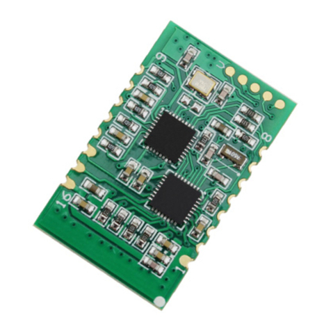
1. Overview
This document describes the pin definition, electrical characteristics and structural dimensions of the
WH-LTE-7S1-E module.
Combined with this document and other application documents of WH-LTE-7S1-E module, users can quickly
embed the module in various terminal devices to design mobile communication application schemes.
About the user manual and encapsulation library, please download in this link:
https://www.pusr.com/products/LTE-Cat-1-module.html
2. Introduction
2.1. Specifications
Parameters
Description
Basic Parameters
WH-LTE-7S1-E
Supports B1/B3/B7/B8/B20/B28
Encapsulation
DIP 23pin
Power
3.4V~4.2V / 5~16V (Not coexisting)
Indicators
WORK, NET, LINKA, LINKB, DATA
SIM/USIM
3V/1.8V SIM slot, 2FF
USB interface
USB 2.0 High speed
UART interface
AT commands and data transmission, TTL-3.0V
RF
IPEX
Environmental
Dimensions(mm)
44.4mm×41.8mm×12.5mm
Weight(g)
15g
Temperature
Operating temperature
-30℃~ +75℃
Expansion temperature
-40℃~ +85℃
Storage temperature
-40℃~ +90℃
Humidity
Operating humidity
5%~95% (non-condensing)
Transmission
speed
LTE FDD Rel.13
10MbpsDL/5Mbps UL
GPRS
85.6KbpsDL/85.6Kbps UL(multi-slot class 12)
Bands
LTE FDD
B1/B3/B7/B8/B20
GSM
900/1800MHz
TX Power
FDD:B1/3/7/8/20/28
23dBm±2dB
GSM:900MHz
33dBm±2dB
GSM:1800MHz
30dBm±2dB
Rx Sensitivity
GSM:900MHz
-109.5dBm
GSM:1800MHz
-108dBm

WH-LTE-7S1-E Hardware Manual Technical Support: h.usriot.com
Jinan USR IOT Technology Limited www.pusr.com
4
FDD:B1/3/20
-98dBm
FDD:B7
-97.5dBm
FDD:B8/B28
-98.5dBm
Software
Operating mode
TCP/UDP/HTTPD/SMS transparent transmission
Configuration command
AT+command
Network protocol
TCP/UDP/DNS/FTP/HTTP
Socket number
4
User configuration
Serial/Network/SMS AT command
Features
Socket distribution protocol
Support
FOTA self upgrade
Support
Security
Support
Base station geolocation
Support
FTP upgrade
Support
NTP
Support
2.2. System Diagram
WH-LTE-7S1-E uses a double inline package design, offers multiple communication interfaces: POWER, Reset,
Reload, work status indicators, SIM, USB, UART and so on.

WH-LTE-7S1-E Hardware Manual Technical Support: h.usriot.com
Jinan USR IOT Technology Limited www.pusr.com
5
2.3. Pins Definition
Pin
Name
Direction
Description
1
LINKA
O
Output high level when socket A connection is
established.
2
LINKB
O
Output high level when socket B connection is
established.
3
USB_DM
I/O
USB-
4
USB_DP
I/O
USB+
5
V_PAD
P
3.0V IO Power domain.
6
UTXD1
O
UART data out, data output from module to user
device (3.0V)
7
URXD1
I
UART data in, data input from user device to module
(3.0V)
8
VBUS
P
USB Power
9
WORK
O
Working status indicator, flashes. The high and low
level change every second.
10
POWER KEY
I
Power on and off, low level off.
11
GND
P
Power GND.
12
GND
P
Power GND.
13
DCIN
P
5-16V power.
14
DCIN
P
5-16V power.

WH-LTE-7S1-E Hardware Manual Technical Support: h.usriot.com
Jinan USR IOT Technology Limited www.pusr.com
6
15
NET
O
Network status indicator.
16
VCAP
P
Power supply: 3.4~4.2V, recommend 3.8V. Can not
use with DCIN simultaneously.
17
NC
18
RELOAD
I
Pull down 3~15s to restore to factory settings.
19
RESET
I
Reset, module should restart when this pin is pulled
down.
20
VSIM
P
SIM card power.
21
SIM_DAT
I/O
SIM card data.
22
SIM_CLK
I/O
SIM card clock.
23
SIM_RST
O
SIM card control.
Note:
1. “P” means power supply pin, “I” means the input pin, “O” means the output pin.
2. LINKA, LINKB, WORK, NET pin: high level is 1.8V, if need to be compatible with 7S2, 7S3 design, please
pay attention to level matching to avoid damage module.
3. POWER_KEY and RESET have the same function to control the power on and off of the module.
4. RELOAD and RST pins are compatible with 3.3V and 5V input.
5. NC: pin is not in use.
6. I/O stands for bidirectional data transfer pins.
2.4. Evaluation Board
In order to facilitate application development with 7S1-E conveniently, we supplies the evaluation
board (EVB)--USR-7SX-EVK.

WH-LTE-7S1-E Hardware Manual Technical Support: h.usriot.com
Jinan USR IOT Technology Limited www.pusr.com
7
3. Application Interfaces
3.1. Power Interface
WH-LTE-7S1-E supports DC 5~16V or DC 3.4~4.2V power supply.
3.1.1.DC 5~16V Power Supply
Connecting pins 13 and 14 with 5~16V power supply. When designing the product, please ensure that the
peripheral circuit can provide sufficient power supply capacity, and strictly control it within 5V ~ 16V. It is
recommended to add 220uF electrolytic capacitor at the front end of the pin interface to increase the stability
of the power supply. Reference circuits are as follows:
3.1.2.DC 3.4~4.2V Power Supply
Connecting pin 16 with 3.4-4.2V power supply (Recommend 3.8V, cannot exceed the range), please place a
large capacitor behind DC/DC or LDO to prevent the voltage drop of the external power supply during the
pulse current period. Bypass capacitors stabilize the input voltage.
Reference circuit is as follows:

WH-LTE-7S1-E Hardware Manual Technical Support: h.usriot.com
Jinan USR IOT Technology Limited www.pusr.com
8
3.2. USB Interface
7S1-E module provides a standard USB2.0 interface, supports both High Speed (480Mbps) and Full Speed
(12Mbps) circuits, supports suspend and resume, and can work in HOST mode and DEVICE mode. The USB
interface can map multiple serial ports on the PC by cooperating with the driver. The recommended circuit is
shown in the figure below. The typical voltage of USB interface power supply (USB_VCC) is 5V (range: 4.75 ~
5.25V). According to the different requirements of application products, should consider different
requirements of ESD and EMI. Design recommendations:
1. We recommend a common-mode suppression filter or 0 ohm resistor in the USB circuit to facilitate
subsequent debugging.
2. When used as an operation interface or debugging interface, the protection of ESD interface must be
considered on the USB signal line, the junction capacitance of ESD is not more than 3pF. TVS
recommends SEMTECH's RClamp0521P.TCT or INFINEO's ESD0P2RF-02LRHE6327. Other devices of the
same specification can also be selected according to the parameters.
3. USB_DP and USB_DM must be in differential signal, try to keep the two lines the same length, keep the
differential impedance at 90ohm.
4. USB_DP and USB_DM need to be protected by the ground.
PIN
Symbol
Description
Type voltage
3
USB_DM
USB D-
4
USB_DP
USB D+
8
VBUS
USB Power supply
5V
Reference circuit:
3.3. UART Interface
WH-LTE-7S1-E supports below baud rate:
1200,2400,4800,9600,19200,38400,57600,115200,230400,460800,921600
When the I/O of the user's MCU is not 3.0V, level matching is needed to achieve communication with
WH-LTE-7S1-E module. The conversion circuit is as follows:

WH-LTE-7S1-E Hardware Manual Technical Support: h.usriot.com
Jinan USR IOT Technology Limited www.pusr.com
9
TXD:
RXD:
V_PAD is the module serial power pin (3.0V). VDD is the user’s MCU level. For triodes, S9014/J6 of JCET Group
is recommended, or other devices of the same specification.
3.4. SIM Interface
The module provides an ISO 7816-3 standard SIM card interface that automatically recognizes 3.0V and 1.8V
SIM cards.

WH-LTE-7S1-E Hardware Manual Technical Support: h.usriot.com
Jinan USR IOT Technology Limited www.pusr.com
10
WH-LTE-7S1-E has integrated SIM card function and can be used directly, users can also design according to
the needs with the SIM pins.
Recommendations:
1. In order to prevent the damage of USIM card and chip caused by static electricity, it is necessary to add
TVS tube for electrostatic protection. Please select devices with rated reverse working voltage VRWM
=5V and junction capacitance CJ < 10 pF. The reference ground of the antistatic device and the module
must be connected.
2. It is suggested to use VSIM power to pull up SIM_DATA 10K to ensure that SIM_DATA has a stable high
level in three states, so as to improve the driving ability and the edge characteristics of its waveform.
3. In order to meet the requirements of 3GPP TS 51.010-1 protocol and EMC certification, it is
recommended to place the SIM card holder close to the SIM card interface of the module to avoid
serious distortion of the waveform and influence of signal integrity due to too long wiring.
4. SIM_CLK and SIM_DAT should be protected by the ground.
5. Please parallel a capacitor of 0.1uF and 33pF between VSIM and GND, and a capacitor of 33pF between
SIM_CLK, SIM_RST, SIMA_DAT and GND to filter the interference of RF signals.
6. The ESD protection device should be placed close to the SIM card slot.
PIN
Symbol
Description
Type(V)
20
VSIM
SIM power
1.8/3.0
21
SIM_DAT
SIM data I/O
1.8/3.0
22
SIM_CLK
SIM clock I/O
1.8/3.0
23
SIM_RST
SIM reset I/O
1.8/3.0

WH-LTE-7S1-E Hardware Manual Technical Support: h.usriot.com
Jinan USR IOT Technology Limited www.pusr.com
11
3.5. Indicators
WH-LTE-7S1-E provides LED to display the working status of the module.
PIN
Symbol
Description
Type voltage
1
LINKA
Socket A status
3.0V
2
LINKB
Socket B status
3.0V
9
WORK
Module work status
3.0V
15
NET
Network status
3.0V
WH-LTE-7S1-E itself provides 3 status indicator lights:
POWER: Always on after the module is powered on.
NET: Flashes after connecting to the network.
WORK: Flashes after the module works normally.
It is recommended to drive the indicator light through a triode, and connect the positive pole of the light with
a stable voltage.
Reference circuit:

WH-LTE-7S1-E Hardware Manual Technical Support: h.usriot.com
Jinan USR IOT Technology Limited www.pusr.com
13
3.6. Reset/Reload
WH-LTE-7S1-E supports hardware reset and restore the factory settings:
RESET: Pull down the “RESET” pin for 0.5s, then pull up or open it.
Reload: Pull down for 3~15s, then pull up or open it to restore the factory settings.
Reference circuit:
3.7. Turn on/off Module Using PWRKEY
If unused, must keep this pin open. When the module is powered on, can pull down the PWRKEY pin to
restart the module. Reference circuit is as follows:
PIN
Symbol
Description
Type voltage
10
PWRKEY
Power pin, pull up by default.
VBAT

WH-LTE-7S1-E Hardware Manual Technical Support: h.usriot.com
Jinan USR IOT Technology Limited www.pusr.com
14
4. Electrical Characteristics
4.1. Operating/Storage Temperature
Parameter
Min
Max
Operating temperature
-35℃
+75℃
Expansion temperature
-40℃
+85℃
Storage temperature
-40℃
+90℃
Note:
When the module works in the operating temperature range, the related performance meets the
requirements of 3GPP standard.
When works in the expansion temperature, the module can still keep the normal working state and has the
functions of voice, SMS and data transmission. There will be no irreversible failure, the radio frequency
spectrum and network are basically unaffected. Only a few parameters, such as output power, may be outside
the range of the 3GPP standard. When the temperature returns to the normal operating temperature range,
all the indicators of the module still meet the 3GPP standard.
4.2. Power Supply
Paramete
Pin
Min.
Typ.
Max.
Input Voltage
13、14
5V
12V
16V
Input Voltage
16
3.4V
3.8V
4.2V
4.3. IO Voltage Range
For SIM power pin USIM_VDD:
1.8V U(S)IM: Class C, USIM_VDD=1.8V
3.0V U(S)IM: Class B, USIM_VDD=3.0V
For RST, POWER KEY and others:
1.8V I/O voltage parameters:
Symbol
Parameter
Min
Typ
Max
Unit
VIH
High-level input voltage
1.17
1.8
1.8
V
VIL
Low-level input voltage
-0.4
0
0.63
V
VOH
High-level output voltage
1.35
1.8
1.8
V
VOL
Low-level output voltage
0
0
0.45
V

WH-LTE-7S1-E Hardware Manual Technical Support: h.usriot.com
Jinan USR IOT Technology Limited www.pusr.com
15
3.0V I/O voltage parameters:
Symbol
Parameter
Min
Typ
Max
Unit
VIH
High-level input voltage
2.1
3.0
3.0
V
VIL
Low-level input voltage
0
0
0.6
V
VOH
High-level output voltage
2.1
3.0
3.1
V
VOL
Low-level output voltage
0
0
0.45
V
4.4. IO Current Range
IO pin
Maximum input current
Maximum drive current
IO current
4mA
4mA
5. Mechanical Characteristics
5.1. Reflow Soldering
Table of contents
Other USR IOT Control Unit manuals

USR IOT
USR IOT USR-K3 Setup guide

USR IOT
USR IOT USR-BLE100 User manual

USR IOT
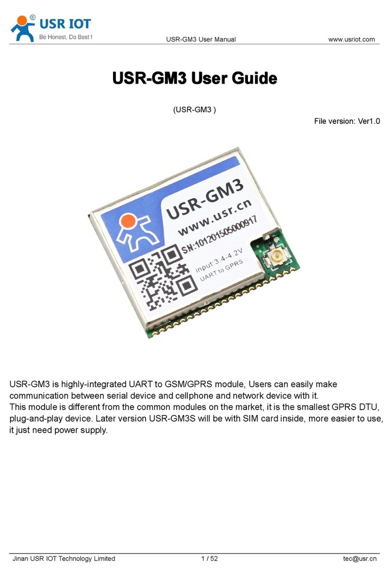
USR IOT USR-GM3 User manual

USR IOT
USR IOT USR-C210 User manual

USR IOT
USR IOT USR-BLE100 User manual

USR IOT
USR IOT USR-TCP232-T2 User manual

USR IOT
USR IOT USR-TCP232-ED2 User manual

USR IOT
USR IOT USR-K5 Quick setup guide

USR IOT
USR IOT USR-WIFI232-A2 User manual

USR IOT
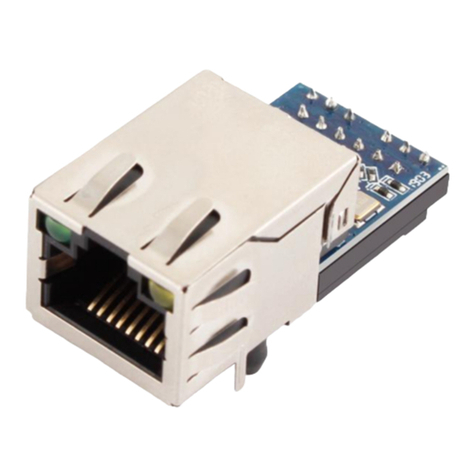
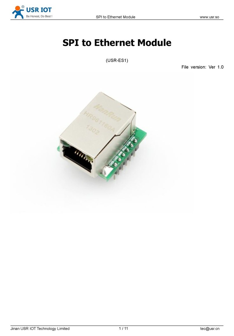
USR IOT USR-ES1 User manual
Popular Control Unit manuals by other brands

Jolywood
Jolywood M6 installation manual

ITW
ITW SIMCO ION Blowflex Easy user manual

PDi
PDi PD295-001 Installation and operating instructions

Yoshitake
Yoshitake TA-16 Series product manual

DEEP SEA ELECTRONICS
DEEP SEA ELECTRONICS DSEGenset DSE3110 Operator's manual

Pentair
Pentair HYPRO PROSTOP-E Installation and operation manual