UTE UH-4U User manual
www.ute.de
UH-4U
4K HDMI2.0 Switcher 4x1
All Rights Reserved
Version: UH-4U(Build2.0)_2018V1.1
User Manual
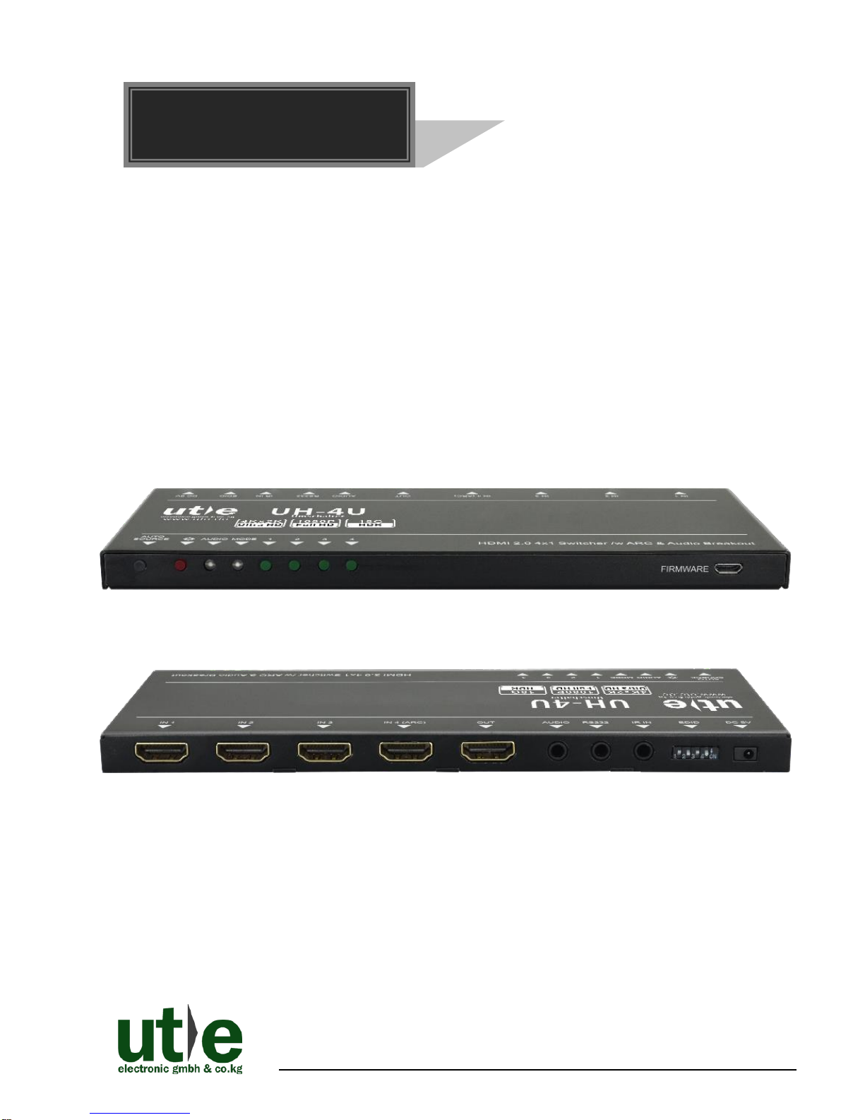
UH-4U: 4K HDMI2.0 4x1 Switcher
U.T.E. electronic GmbH & Co. KG www.ute.de
Preface
Read this user manual carefully before using the product. Pictures are shown in this
manual for reference only. Different models and specifications are subject to real
product.
This manual is only for operation instruction, please contact your local dealer or
distributor for maintenance assistance. The functions described in this version were
updated till June, 2018. In the constant effort to improve the product, we reserve the
right to make functions or parameters changes without notice or obligation. Please
refer to the dealers for the latest details.
All product function is valid till 2018-06-04.
Trademarks
Product model and logo are trademarks of U.T.E. electronic GmbH & Co. KG.
Any other trademarks mentioned in this manual are acknowledged as the properties of
the trademark owner. No part of this publication may be copied or reproduced without
the prior written consent.
FCC Statement
This equipment generates, uses and can radiate radio frequency energy and, if not
installed and used in accordance with the instructions, may cause harmful interference
to radio communications. It has been tested and found to comply with the limits for a
Class B digital device, pursuant to part 15 of the FCC Rules. These limits are designed
to provide reasonable protection against harmful interference in a commercial
installation.
Operation of this equipment in a residential area is likely to cause interference, in
which case the user at their own expense will be required to take whatever measures
may be necessary to correct the interference.
Any changes or modifications not expressly approved by the manufacture would void
the user’s authority to operate the equipment.

UH-4U: 4K HDMI2.0 4x1 Switcher
U.T.E. electronic GmbH & Co. KG www.ute.de
SAFETY PRECAUTIONS
To ensure the best performance from the product, please read all instructions carefully
before using the device. Save this manual for further reference.
⚫Unpack the equipment carefully and save the original box and packing material for
possible future shipment.
⚫Follow basic safety precautions to reduce the risk of fire, electrical shock and injury
to persons.
⚫Do not dismantle the housing or modify the module. It may result in electrical shock
or burn.
⚫Using supplies or parts not meeting the products’ specifications may cause damage,
deterioration or malfunction.
⚫Refer all servicing to qualified service personnel.
⚫To prevent fire or shock hazard, do not expose the unit to rain, moisture or install this
product near water.
⚫Do not put any heavy items on the extension cable in case of extrusion.
⚫Do not remove the housing of the device as opening or removing housing may
expose you to dangerous voltage or other hazards.
⚫Install the device in a place with fine ventilation to avoid damage caused by
overheat.
⚫Keep the module away from liquids.
⚫Spillage into the housing may result in fire, electrical shock, or equipment damage. If
an object or liquid falls or spills on to the housing, unplug the module immediately.
⚫Do not twist or pull by force ends of the optical cable. It can cause malfunction.
⚫Do not use liquid or aerosol cleaners to clean this unit. Always unplug the power to
the device before cleaning.
⚫Unplug the power cord when left unused for a long period of time.
⚫Information on disposal for scrapped devices: do not burn or mix with general
household waste, please treat them as normal electrical wastes.

UH-4U: 4K HDMI2.0 4x1 Switcher
U.T.E. electronic GmbH & Co. KG www.ute.de
Contents
1. Product Introduction to UH-4U....................................................................................1
1.1 Features ............................................................................................................1
1.2 Package List......................................................................................................2
2. Panel Description of UH-4U........................................................................................3
2.1 Front Panel........................................................................................................3
2.2 Rear Panel.........................................................................................................4
3. System Connection.....................................................................................................5
3.1 Usage Precaution..............................................................................................5
3.2 System Diagram of UH-4U................................................................................5
3.3 Connection Procedures.....................................................................................6
3.4 Application.........................................................................................................6
4. Source Button Control.................................................................................................7
4.1 Manual Switching...............................................................................................7
4.2 Automatic Switching...........................................................................................7
5. IR Remote Control......................................................................................................8
6. RS232 Control............................................................................................................9
6.1 RS232 Control Software....................................................................................9
6.1.1 Installation/uninstallation of RS232 Control Software..............................9
6.1.2 Basic Settings..........................................................................................9
6.2 RS232 Commands ..........................................................................................11
6.2.1 Signal Switching....................................................................................11
6.2.2 Source Device Control...........................................................................12
6.2.3 Display Device Control ..........................................................................13
6.2.4 Audio Selection......................................................................................13
6.2.5 System Control......................................................................................13
7. EDID Management...................................................................................................14
7.1 Predefined EDID Setting..................................................................................14
7.2 User Defined EDID Setting..............................................................................15
8. ARC Mode ................................................................................................................16
9. Firmware Upgrade....................................................................................................17

UH-4U: 4K HDMI2.0 4x1 Switcher
U.T.E. electronic GmbH & Co. KG www.ute.de
10. Technical Specification............................................................................................18
11. Panel Drawing.........................................................................................................19
12. Troubleshooting & Maintenance .............................................................................20
13. Customer/ After-sales Service ................................................................................21

UH-4U: 4K HDMI2.0 4x1 Switcher
U.T.E. electronic GmbH & Co. KG 1 www.ute.de
1. Product Introduction to UH-4U
The UH-4U is an ultrathin auto switcher with four HDMI video inputs and one HDMI
output. This switcher supports HDMI video resolution up to 4Kx2K@60Hz 4:4:4 HDR
and multichannel audio. Except passing EDID information from the display, there are
multiple built-in EDID settings to simplify an installation. The switcher will de-embed
digital stereo audio to provide an analog audio source for an existing audio system.
The switcher also supports audio return channel (ARC) for transmitting audio back to
HDMI input and audio output ports from the connected display.
In auto-switch mode, it switches to an HDMI input as soon as a new source is
connected. When the active input is removed, the switcher will select the first source
on the lowest numbered input. The switcher may also be controlled via RS232, IR with
the included remote, or from the source button on the front of the switcher. If select any
of the inputs by “SOURCE” button on the front panel, IR Remote, or sending RS232
command, the corresponding indicator will illuminate to show real-time switching
status.
1.1 Features
⚫Switches any one of four HDMI inputs to one HDMI output.
⚫Supports video resolution up to 4Kx2K@60Hz 4:4:4 HDR.
⚫18Gbps high bandwidth.
⚫Fully compliant with the HDMI 2.0 and HDCP2.2 specifications.
⚫Supports audio return channel (ARC).
⚫Advanced EDID management: multiple preset and user defined allowed.
⚫Controllable via RS232 and IR.
⚫Supports CEC.
⚫Provides seven LEDs to indicate the current operating status and to assist
troubleshooting an installation.
⚫Firmware upgrade by Micro-USB port.

UH-4U: 4K HDMI2.0 4x1 Switcher
U.T.E. electronic GmbH & Co. KG 2 www.ute.de
1.2 Package List
⚫1x UH-4U: 4K HDMI2.0 4x1 Switcher with HDR Support
⚫2x Mounting Ears
⚫4x Mounting Screws
⚫4x Plastic Cushions
⚫1x RS232 Cable (3.5mm to DB9)
⚫1x IR Remote
⚫1x IR Receiver
⚫1x Power Adapter (5V DC 1A)
⚫1x User Manual
Note: Please confirm if the product and the accessories are all included, if not,
please contact with your dealer. Please contact your dealer immediately if any
damage or defect in the components is found.
UH-4U: 4K HDMI2.0 4x1 Switcher
U.T.E. electronic GmbH & Co. KG 3 www.ute.de
2. Panel Description of UH-4U
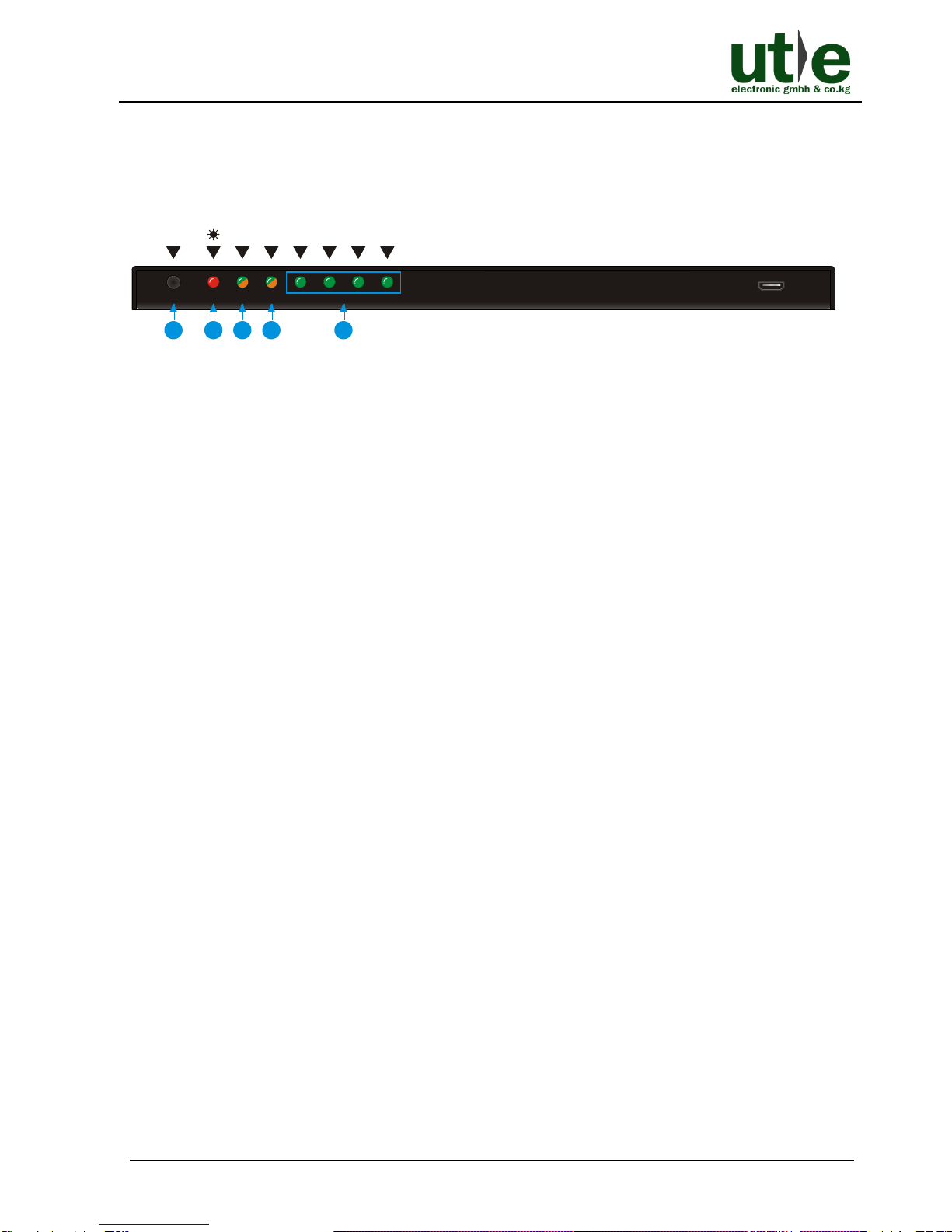
2.1 Front Panel
Figure 2-1 Front Panel UH-4U(Build2.0)
①Auto/Source Button:
⚫Press to switch to next input source.
⚫Press and hold at least three seconds to switch between manual mode and auto
mode.
②Power LED: The LED illuminates red when power is applied.
③Audio Mode LED:
⚫Illuminates green when de-embedding audio.
⚫Illuminates yellow when in ARC mode.
④Switching Mode LED:
⚫Illuminates green in manual switch mode.
⚫Illuminates yellow in auto-switch mode.
⑤Input 1~4 LED: The LED illuminates green when there is HDMI input on the
corresponding channel.
Note: Pictures shown in this manual are for reference only, different model and
specifications are subject to real product.
FIRMWARE
AUTO
SOURCE AUDIO MODE 1 2 3 4
12345
UH-4U: 4K HDMI2.0 4x1 Switcher
U.T.E. electronic GmbH & Co. KG 4 www.ute.de
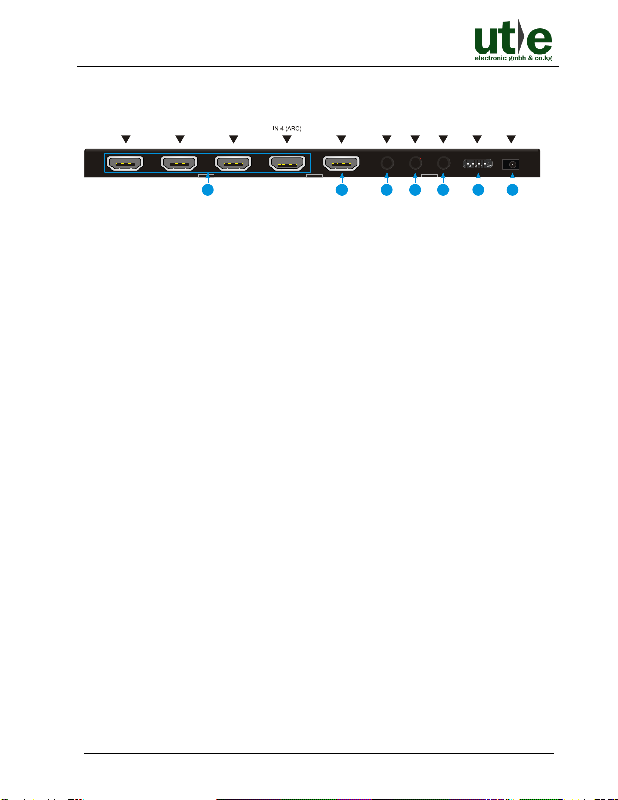
2.2 Rear Panel
Figure 2-2 Rear Panel UH-4U(Build2.0)
①IN1~IN4: Four type-Afemale HDMI input ports to connect HDMI sources.
The input 4 port supports ARC.
②OUT: Type-A female HDMI output port to connect HDMI display.
③AUDIO: 3.5mm mini jack for analog audio output.
④RS232: 3.5mm mini jack to connect control device (e.g. PC).
⑤IR IN: 3.5mm mini jack to connect the included IR remote.
⑥EDID: 4-pin DIP switch for EDID setting.
⑦DC 5V: DC barrel port to connect a 5V DC AC power adapter.
Notes:
Pictures shown in this manual are for reference only, different model and
specifications are subject to real product.
Output HDCP compliant status depends on input signal. When the input signal is
with HDCP, then output signal is with HDCP and vice versa.
DC 5VEDIDIR INRS232AUDIOOUT
IN 1 IN 2 IN 3
1234567
UH-4U: 4K HDMI2.0 4x1 Switcher
U.T.E. electronic GmbH & Co. KG 5 www.ute.de
3. System Connection
3.1 Usage Precaution
⚫Make sure all components and accessories included before installation.
⚫System should be installed in a clean environment with proper temperature and
humidity.
⚫All of the power switches, plugs, sockets, and power cords should be insulated and
safe.
⚫All devices should be connected before power on.
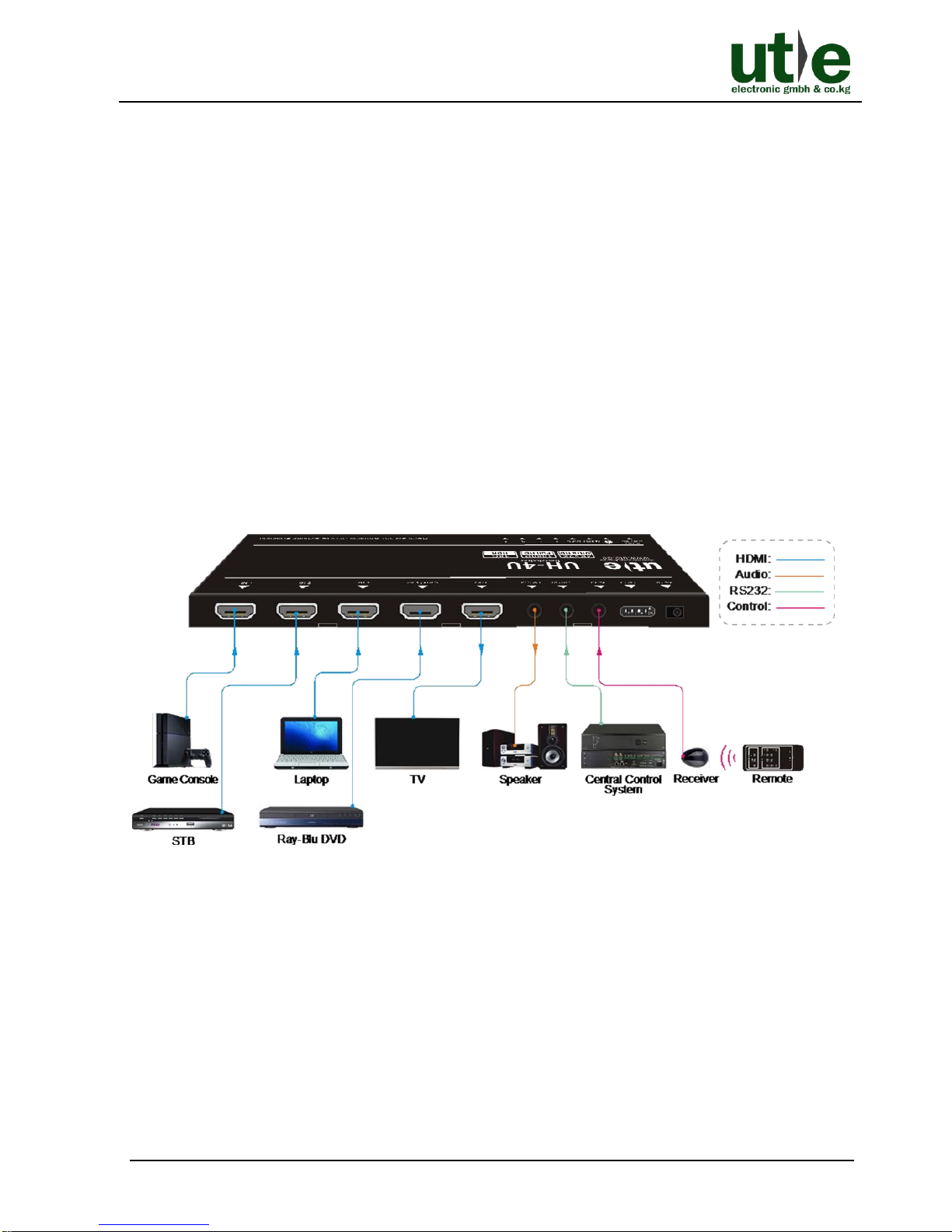
3.2 System Diagram of UH-4U
The following diagram illustrates typical input and output connections that can be
utilized with this switcher:
Figure 3-1 System Diagram UH-4U(Build2.0)
Note: Pictures shown in this manual are for reference only, different model and
specifications are subject to real product.
Table of contents
Other UTE Switch manuals


