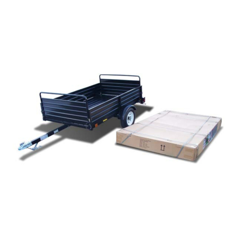
UtilityMate UM4848 User manual

TRAILER ASSEMBLY GUIDE
ALL MODELS UM4848, UM4872, UM4884, UM6096, EZ & SE
Read the owner’s manual completely before you assemble & use the trailer.
UtilityMate®TrailerKit
TrailerAssemblyGuide
©2005 V.L. Webb, All Rights Reserved

- 1 -
2005 V.L. Webb, All Rights Reserved
At-A-Glance Trailer Assembly Overview
VERY IMPORTANT; ALWAYS REFER TO YOUR OWNER’S MANUAL FOR
PROPER OPERATING AND SAFETY INFORMATION REGARDING YOUR
TRAILER. INCASE OF LOSS GO TO WWW.UTILITYMATE.COM
BEFORE & AFTER PICTURE REMOVE PARTS & FLIP FRAME
GATHER TOOLS / METRIC 5. TONGUE ASSEMBLY
6. AXLE ASSEMBLY 7. LIGHT ASSEMBLY

- 2 -
2005 V.L. Webb, All Rights Reserved
8. SAFELY FLIP TRAILER UP RIGHT 9. APPLY VIN & TIRE LABELS
Step By Step Assembly Overview
1. _____ STEP 1; Read owner’s manual & refer to it during assembly.
2. _____ STEP 2; Open & remove all parts from on top of the trailer frame.
3. _____ STEP 3; Flip the trailer frame upside down for assembly.
4. _____ STEP 4; Gather the metric tools required to assemble the trailer.
•11mm, 13mm, 17mm, 19mm, 21mm, 24mm sockets w/ extension
•11mm, 13mm, 17mm, 19mm, 24mm open end wrench(s)
•Electrical wire stripers, black electrical tape (optional)
•Locate bolt bag & U bolt bag from parts, put in secure spot for use…
5. _____ STEP 5;Tongue Assembly, in the order stated, mount the 24”
tongue mount (4 bolts), the tongue, L pin, coupler, and safety chains.
6. _____ STEP 6;Axle Assembly, in the order stated, mount the slipper
spring and fenders, mount axle to springs with u bolts, mount tires, torque
the lug nuts to 65-70 lbs.
7. _____ STEP 7;Light Assembly, in the order stated, mount the side
markers, mount the rear light protectors, mount the rear lights.
8. _____ STEP 8; Using 2 or more people, safely flip the trailer over.
9. _____ STEP 9; Apply VIN Tag & Tire Placard, mount the side markers, by
law the labels must be mounted on the driver’s side. The best placement
for the labels is on the driver’s side of the tongue.
10._____ STEP 10;VERY IMPORTANT: With your OWNER’S MANUAL in
hand, completely go over your trailer completely and make sure YOU
properly installed all parts and that they are working correctly.
REMEMBER; Always, always refer to your owner’s manual for all the safety,
maintenance, tire inflation, load capacity, and operator instructions.

- 3 -
2005 V.L. Webb, All Rights Reserved
Step 5: Tongue Assembly Checklist
ATTACH TONGUE MOUNT TO FRAME ATTACH PIVOT BOLT & L PIN TO FRAME
ATTACH COUPLER & SAFETY CHAINS ATTACH 12V TONGUE & FRAME PLUG
_____ RECOMMENDED TOOLS NEEDED; 17mm, 19mm, 20mm, and 24mm
SOCKETS W/ RATCHET and EXTENSION. Also 17mm, 19mm, 20mm, and 24mm
OPEN END WRENCHES.
•Use the 19mm ratchet & open end wrench to attach and securely tighten the (4)
1” long bolts, washers and lock nuts that fasten the tongue mount to the front of
the trailer frame.
•Lay the tongue into load bearing guide, making sure the tongue stand is pointed
upward and it is out past the front of the trailer frame. Use the 24mm ratchet &
open end wrench to attach the 4 ½” pivot bolt and lock nut to the back of the
tongue mount. Slide the removable L pin through the front of the tongue mount
hole and tongue hole, then secure the L pin using the carter pin provided.
•Use the 20mm ratchet & open end wrench to attach and securely tighten the (2)
3 ¼” long bolts, washers and lock nuts that fasten the coupler to the tongue. Use
the 17mm 1½” long bolts, washers and lock nuts to mount the safety chains to
the V stand on the tongue. Bolt heads are to be located on the outside of the V,
the bolt is slid through the last chain link on the inside of the V stand and secured
with a lock nut.
•Connect the 12v tongue wire plug into the 12v trailer frame wire plug.

- 4 -
2005 V.L. Webb, All Rights Reserved
Step 6: Axle Assembly Checklist
AXLE, SPRINGS, TIRES, FENDERS ATTACH SLIPPER SPRING & FENDER
ATTACH AXLE TO SPRING SET FENDER, SPRING, AXLE MOUNT
_____ RECOMMENDED TOOLS NEEDED; 17mm, 18mm, 19mm, and 21mm
SOCKETS W/ RATCHET and LONG EXTENSION. Also 17mm, 18mm, and 19mm
OPEN END WRENCHES.
•Lay slipper springs in spring track with spring eye facing towards front of trailer
frame and the spring slipper facing the rear of the trailer.
•To correctly place fenders into position, as seen in the picture above, make sure
the U shaped mount fender bracket is always facing to the rear of trailer frame so
that the fenders align properly. The fenders should always center on the wheel if
mounted correctly. TIP: After mounting the fender brackets (zip tied to fender
holes), hold the fender in place under the hub and eye it before mounting the
fender to the frame to make sure it is on the correct side.
•Use the 18mm ratchet & 19mm open end wrench to attach and securely tighten
the (4) 3½” long bolts, washers and lock nuts that fasten & attach the springs and
fenders to the trailer frame.
•Lay axle across springs with the nipple on each spring into the nipple hole on the
axle. Use the 17mm ratchet & open end wrench to attach (4) “U” bolts and (2)
spring plates. Securely tighten down the axle to both springs.
•Remove the lug nuts from th hub, slide the wheels on to the hub lugs, and put
the lug nuts back on nipple in (use the 21mm ratchet w/ extension. Refer to
owner’s manual for proper torque (65-70 lbs.) and maintenance.

- 5 -
2005 V.L. Webb, All Rights Reserved
Step 7: Light Assembly Checklist
REAR LIGHT ASSEMBLY WIRE CONNECTORS
WIRE NUTS & PROPER GROUND SIDE MARKER PLACEMENT
_____ RECOMMENDED TOOLS NEEDED; 12mm, AND 13mm SOCKETS W/
RATCHET and EXTENSION. Also 12mm, AND 13mm OPEN END WRENCHES, WIRE
STRIPPER, ELECTRICAL TAPE for taping wire strands together as needed.
•Use the 13mm ratchet & open end wrench mount the tail light protectors to rear
side of trailer. Make sure that the large opening is facing the rear of the trailer.
Attach and securely tighten the (4) 1½” long bolts, washers and lock nuts that
mount the tail light protectors securely to the trailer frame. The light protectors
can be mounted in either a 1.) Flush position if the trailer is to be used as a flat
bed and 2.) Extended height position. PLEASE NOTE: Make sure the 12v wires
are pulled through the protectors and not pinched when mounting the brackets.
•Identify which light is the right side and left side by looking at the bottom of the
lights. The left light (driver’s side) has a clear lens in the bottom for the
illumination of a license plate. Use a 12mm to attach rear lights to bracket.
•Properly attach the 12v wires and ground wire to the back of the tail light(s) Using
wire connectors, connect color to color and make sure that the ground wire is
bolted down to the light / light bracket assembly. INSTALL SIDE MARKERS up
front, big hole for wires, small hole for post on light.

- 6 -
2005 V.L. Webb, All Rights Reserved
FLIP TRAILER OVER & FINAL CHECK
SAFELY FLIP TRAILER UPRIGHT CHECK LATCHES & DROP GATE
CHECK DUMP FUNCTION ATTACH VIN TAG & TIRE LABEL
STEP 8; USE EXTREME CAUTION: Using at least (2) strong bodied people, safely flip
the trailer over by standing the trailer on end (its rear frame) and carefully flipping it over
to support itself on the wheels and the tongue stand. Do not attempt this if you do not
have; 1.) Adequate clearance above and from side to side or 2.) Enough man power
that can SAFELY handle the weight of the trailer when flipping it over.
STEP 9; Apply VIN Tag & Tire Placard, mount the side markers, by law the
labels must be mounted on the driver’s side. The best placement for the labels is
on the driver’s side of the tongue.
STEP 10; VERY IMPORTANT: With your OWNER’S MANUAL in hand, completely
go over your trailer completely and make sure YOU properly installed all parts
and that they are working correctly.
REMEMBER; Always, always refer to your owner’s manual for all the safety,
maintenance, tire inflation, load capacity, and operator instructions.
ENJOY YOUR TRAILER !!!

- 7 -
2005 V.L. Webb, All Rights Reserved
DETAILED PARTS LIST & DRAWING
No. Description Description Qty
1 Coupler Coupler 1
2 Tongue Tongue 1
3 Trailer Frame Trailer Frame 1
4 Fender left Fender left 1
5 Fender right Fender right 1
6 Axle Axle 1
7 U-Bolt U-Bolt 4
8 Leaf Spring Leaf Spring 2
9 Tire/Wheel Tire/Wheel 2
10 Back Gate Back Gate 1
11 Tail Light Tail Light 2
12 Tail Light Bracket Right Tail Light Bracket Right 1
13 Tail Light Bracket Left Tail Light Bracket Left 1
14 License Plate Holder License Plate Holder 1
4601 Safety Chain Single w/Hook Safety Chain Single w/Hook 2
4602 M10*30 Bolt 2/5"-17-1.18" 2
4603 Flat Washer 10 4
4604 M10 Nylon Lock Nut 2
4605 M12*85 Bolt 1/2"-15-3.35" 2
4606 Flat Washer 12 4
4607 M12 Nylon Lock Nut 2
4608 M12*30 Bolt 1/2"-15-1.18" 4
4609 Flat Washer 12 8
4610 M12 Nylon Lock Nut 4
4611 M12*90 Bolt 1/2"-15-3.54" 4
4612 Flat Washer 12 8
4613 M12 Nylon Lock Nut 4
4614 Spring Mount Plate 2
4615 Flat Washer 10 8
4616 M10 Nylon Lock Nut 8
4617 Tire Lug Nut 10
4618 M8*20 Bolt 1/3"-20-0.79" 4
4619 Flat Washer 8 8
4620 M8 Nylon Lock Nut 4
4621 M12*30 Bolt 1/2"-15-1.18" 4
4622 Flat Washer 12 8
4623 M12 Nylon Lock Nut 4
4624 M16*110 Bolt 3/5"-13-4.33" 1
4625 Flat Washer 16 2
4626 M16 Nylon Lock Nut 1
FOR REFERENCE USE ONLY

- 8 -
2005 V.L. Webb, All Rights Reserved

- 9 -
2005 V.L. Webb, All Rights Reserved
BY
G
W
G
B
B
B
B
B
B
B
B
B
BY
YG
W
Y
B
W
WIRING DIAGRAM 3
This manual suits for next models
5
Table of contents
Other UtilityMate Utility Vehicle manuals
Popular Utility Vehicle manuals by other brands

NC
NC HT1.0 Original instructions

Taylor-Dunn
Taylor-Dunn C0-425-36 Operation, troubleshooting and replacement parts manualooting and replacement parts manual

Kato Imer
Kato Imer CARRY 105 ELECTRIC POWER operating instructions

Club Car
Club Car FE 350 Maintenance and Service Supplement

TrailMax
TrailMax TD-42-T manual

Ironhorse Trailers
Ironhorse Trailers One bike owner's manual