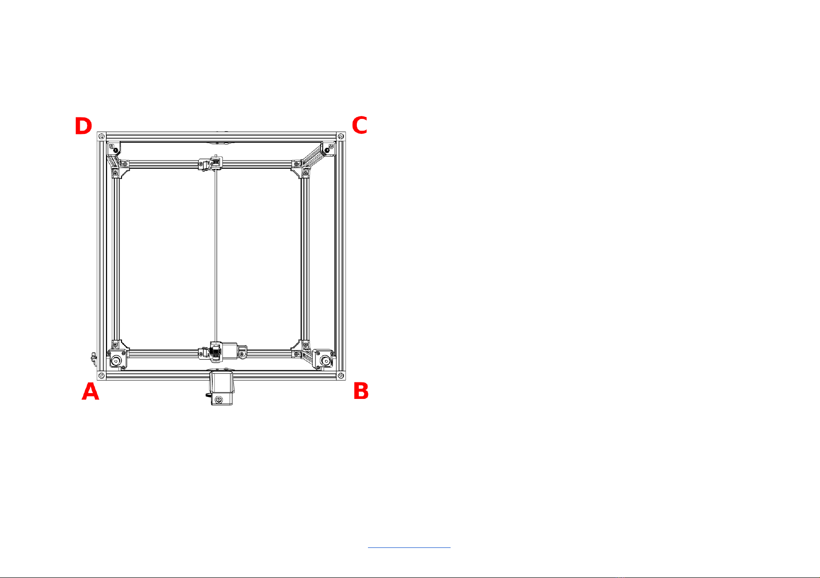
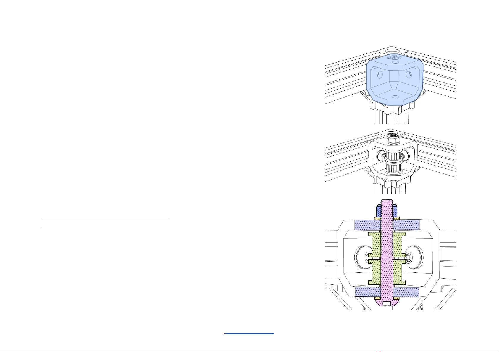
Corner part of the frame
Hardware parts
12 500 mm V-slot Rails with M5 threaded/tapped ends
8 Corner Cubes
24 M5 x 8mm Countersunk Bolts
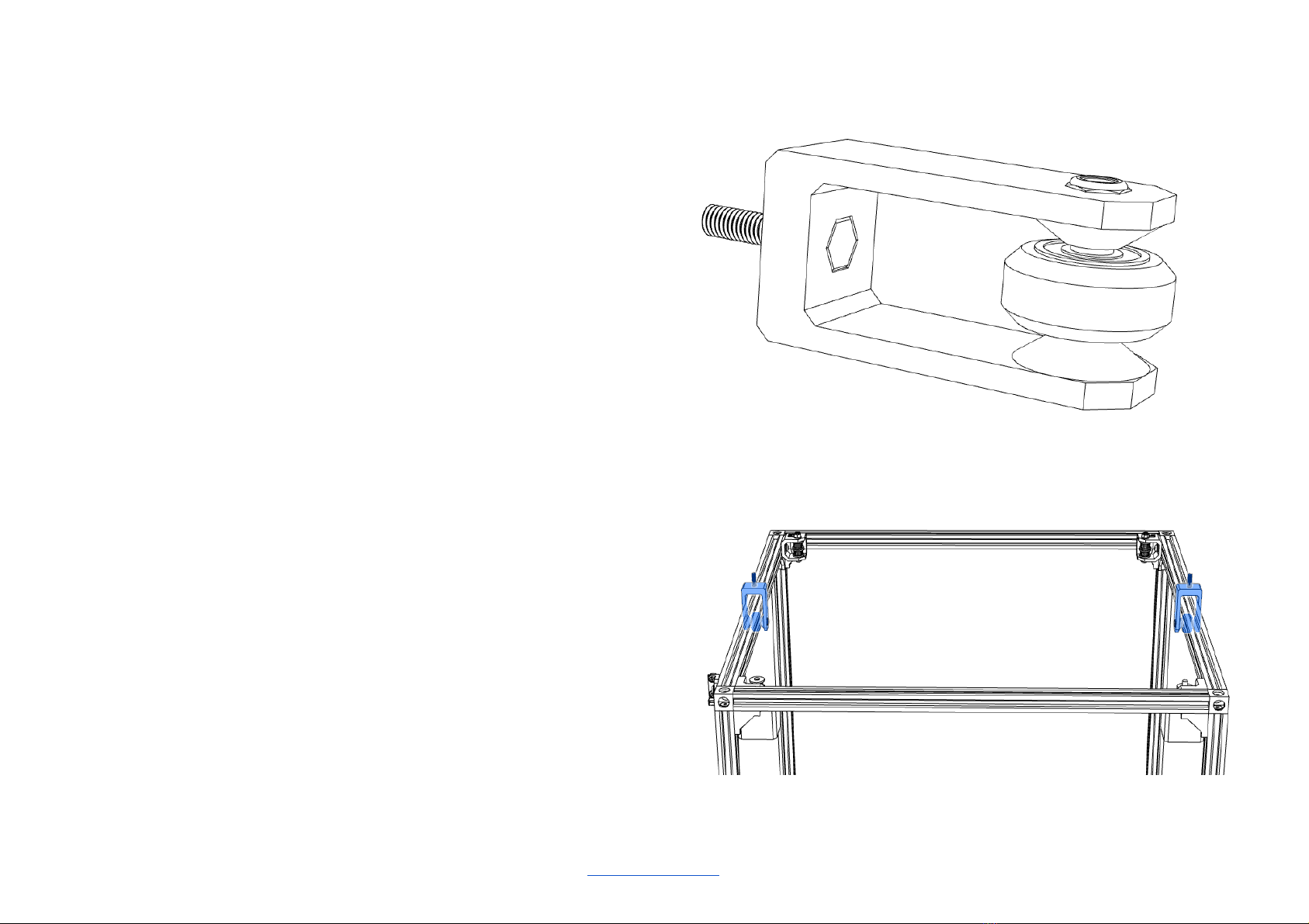
20 Cast Corner Brackets, large 20mm x 28mm x 28mm
40 M5 x 10 mm Button Head Screws
40 M5 Washers
68 M5 Tee Nuts
Printed parts
none
Videos
Fusion 360 animation - Base Frame Assembly
Live Build - Main Frame - The Corners
Step by step
1. Make sure you’re building on a completely flat surface.
2. Start with loosely fastening the corner brackets with the button head screws
and washers.
3. Add the right amount of tee nuts before mounting the corner cubes, see
separate overview.
4. Add the corner cubes using the countersunk screws. Tighten the corner cubes
first - do not use too much force when tightening.
5. Tighten the corner bracket screws carefully.
6. In real life it is almost impossible to square the frame TRUE 90 degrees in 3
dimensions. Do your best. What is important is that the Y-axis is parallel to each
other, and that the X-axis is adjusted 90 degrees to the Y axis.
V-King MK2 Assembly Manual 2021-02-27 5 / 41
https://vkingprinter.com/