V-Sun TK205 User manual

TK205 WATCH GPS TRACKER
User’s Manual
(V1.0)

Table of Contents
Chapter 1 Welcome to Use It ............................................................................................................3
1.1 About the Product................................................................................................................3
1.2 Safety Considerations..........................................................................................................3
1.2.1 Storage Considerations.............................................................................................3
1.2.2 Batteries Operating Instructions...............................................................................3
1.2.3 Whole System Operating Instructions......................................................................3
1.2.4 Charger Operating Instructions................................................................................4
1.2.5 Maintenance Considerations....................................................................................4
1.2.6 Network Service.......................................................................................................4
1.3 About GPS...........................................................................................................................4
1.3.1 GPS Definition.........................................................................................................4
1.3.2 About Signals...........................................................................................................5
1.3.3 About the Search System..........................................................................................5
1.4 Maintenance and Repair......................................................................................................5
Chapter 2 General Introduction.........................................................................................................6
2.1 Appearance..................................................................................................................................6
2.2 Functions.............................................................................................................................6
2.3 Hardware.............................................................................................................................6
2.4 Appearance Introduction.....................................................................................................6
Chapter 3 Accessories.......................................................................................................................8
3.1 Desktop battery charger (1).................................................................................................8
3.2 Charger cable (1).................................................................................................................8
3.3 Earphone (1)........................................................................................................................8
3.4 Batteries (2).........................................................................................................................9
Chapter 4 Product Definition..........................................................................................................10
4.1 Interface Definition...........................................................................................................10
Chapter 5 Before use.......................................................................................................................11
5.1 Charging............................................................................................................................11
5.2 Buy the SIM Card .............................................................................................................11
5.3 Insert the SIM card............................................................................................................11
Chapter 6 How to use......................................................................................................................12
6.1 Keys and Jacks..................................................................................................................12
6.2 Operation...........................................................................................................................12
6.2.1 Turn On ..................................................................................................................12
6.2.2 Turn Off..................................................................................................................12
6.2.3 Interface Shift.........................................................................................................12
6.2.4 Emergency Alarm...................................................................................................12
6.2.5 Terminal Active Dial-up.........................................................................................13
6.2.6 Calling and Auto-answer........................................................................................13
2

Chapter 1 Welcome to Use It
1.1 About the Product
Welcome to use the TK205 watch GPS Tracker. This exquisite watch is designed for the
elderly/children positioning and guarding, businessmen safety precautions and field personnel
management. At the same time, it is available with GPS/GPRS function and GSM/SMS/GPRS
communication with a quick signal receiving speed.
1.2 Safety Considerations
To ensure your safety, please read the following Safety Considerations carefully:
1.2.1 Storage Considerations
¾Don’t put this product directly in the sun or in a dusty place or pile it with other electronic
products for fear of damage. Keep it off the equipments with strong electromagnetic radiation
or a strong magnetic field as far as possible.
¾Don’t put its batteries, terminal or charger in a microwave oven or a high-pressure device for
fear of such accidents as circuit damage or fire.
¾Don’t put the terminal on an uneven or unsteady table for fear of malfunction or damage if it
drops on the ground.
¾Keep the product off dampness and water.
1.2.2 Batteries Operating Instructions
¾When the product is first used, please use up the battery power and charge the battery for 2-3
times for not less than 12 hours each time, so as to ensure the battery in good condition.
¾Please charge the battery with the charger provided by our company. All damages due to the
use of any other charger are on the user’ s account.
¾Don’t drop the batteries in fire for fear of burning or explosion of the batteries.
¾Don’t put any stress on the batteries during battery installation, or the batteries will be subject
to leakage, overheat, cracking or burning.
¾Don’t dismantle or refit the batteries for fear of leakage, overheat, cracking or burning.
¾Don’t use or store batteries in a hot place, such as by the fire or a heater, for fear of leakage,
overheat, cracking or burning.
¾In case of such abnormalities as discoloration and a rise in temperature when the battery is
used, charged or stored, please stop use and replace it.
¾Keep the batteries of dampness for fear of overheat, smoking or corrosion.
1.2.3 Whole System Operating Instructions
¾Don’t dismantle or refit the machine on your own. Our company is not responsible for any
damage due to any illegal operation.
¾Don’t use the terminal near an electronic device with weak signals or high precision, or the
radio wave interference might cause wrong operation on the electronic device or other
problems。
¾Don’t put the terminal too close to such magnetic objects as a magnetic card, or the radiation

waves it produces might remove the information saved on the floppy disk, the magnetic card
or the credit card.
¾Keep the batteries of dampness. The entrance of water or other liquids will result in overheat,
creep age or malfunction of the terminal.
1.2.4 Charger Operating Instructions
¾Please use the 220V alternating current only for fear of leakage or burning of or damage to
the terminal or the charger.
¾Don’t short out the charger for fear of electrical shock or smoking of or damage to the
charger.
¾In case of the splashing of water or other liquids into the charger during the battery charging,
please disconnect the charger at once for fear of overheat, burning, electrical shock or
malfunction of the charger.
¾Don’t dismantle or refit the charger for fear of personal injury, electrical shock, fire or
damage to the charger.
¾Don’t use the charger in a wet place, such as a bathroom, for fear of electrical shock, fire or
damage to the charger.
¾Don’t touch the charging charger with your wet hand for fear of electrical shock.
1.2.5 Maintenance Considerations
¾As the terminal, the batteries and the charger are not waterproof, don’t use them in a highly
wet place (such as a bathroom) or in the rain.
¾Only the maintenance personnel specially trained by our company are allowed to repair the
product. Any unauthorized disassembly or repair on this product might disable the warranty
or lead to damage to this product.
1.2.6 Network Service
As the function realization of the product depends on the mobile network service,one
must first apply to the mobile service providers for the GPRS network service for the mobile
phone concerned and that for the SIM card inside the terminal. For more information about
the usage and charge of the SIM card, please consult the local mobile network service
providers.
1.3 About GPS
The following is about how to use the GPS device. Please read it before using the device,
so as to increase its service efficiency.
1.3.1 GPS Definition
GPS is the abbreviation of Global Positioning System, a system developed by the US
Department of Defense and jointly used and managed by the US Department of
Transportation and the former, defining the location by means of satellites. GPS system
consists of 24 satellites, through which the desired information is received by means of
electric waves to work out the current location. Generally the error range for GPS positioning
is below 15 meters.
4

1.3.2 About Signals
When it is first used or used after long idling, it might take 1-2 minutes to electrify the
GPS antenna and check the system. At the same time, try your best to keep the screen at a
right angle with the sky. Under some special circumstances (tunnels, viaducts, underpasses,
metro or building complex), it might be hard for the device to work well on positioning.
1.3.3 About the Search System
If the system is restarted when the locator is moving fast, the search positioning will be
difficult. So it is more advisable to stop it for a period of time.
1.4 Maintenance and Repair
¾Don’t dismantle any part of the system for fear of malfunction. If there is any problem, please
turn to the local agent or after service center.
¾Don’t put the mainframe directly in the sun, dampness, dust or heat. When it is used at the
edge of normal temperature, its normal operation will be affected, but that does not mean any
failure or error. Just take it easy.
¾Avoid abnormal violent vibration or impact.
¾Don’t pull out the SIM card randomly. After inserting the SIM card when the system is
turned on, one must restart the system, or the device cannot work well.
¾Any dirt in the socket will lead to bad contacts and power failure, thus disabling further
charging. So please clean the socket regularly.
¾Often clean the terminal or the charger with a clean dry rag.
5

Chapter 2 General Introduction
2.1 Appearance
(Figure 1)
¾2.2 Functions
¾Guardianship party can get the location information directly through SMS query
¾Call ,dual-entry call function.
¾Auto-answer
¾Low-power alarm
¾SOS Emergency Alarm
¾GPS timing function
2.3 Hardware
¾Charging voltage:110-220V
¾Working temperature -20°-—65°
¾Humidity: 5%-95%
¾Limited working temperature:-30°C -- -40°C, +80°C-- +85°C
¾Storing temperature:-45°C -- +90°C
¾Start-up time, hot start: <1.5s Warm start: <34s Cold start: <35s(Autonomous)
¾Accurate positioning: 3.0 m 2D-RMS , DGPS: 2.5 m
¾Speed Positioning: 0.1m/s, DGPS:0.05m/s
¾Power consumption: standby 48mA(Depending on the system network state and the user’
s operation method)
¾Charging port: DC 5V 3A
2.4 Appearance Introduction
There are five keys on the terminal. The upper left green button is used to turn on/off the
device, the lower left blue button is the mode (interface) shifting key, the upper right button
6

is the emergency dial(SOS)key, and the central right button and the lower right key are dial
keys.(See Figure 2.)
Power on/off
Earphone /Charger
Mode
SOS
Phone 1
Phone 2
(Figure 2)
7

Chapter 3 Accessories
3.1Desktopbatterycharger(1)
(Figure 3)
3.2 Charger cable (1)
(Figure 4)
3.3 Earphone (1)
(Figure 5)
8

3.4 Batteries (2)
(Figure 6)
9
Chapter 4 Product Definition
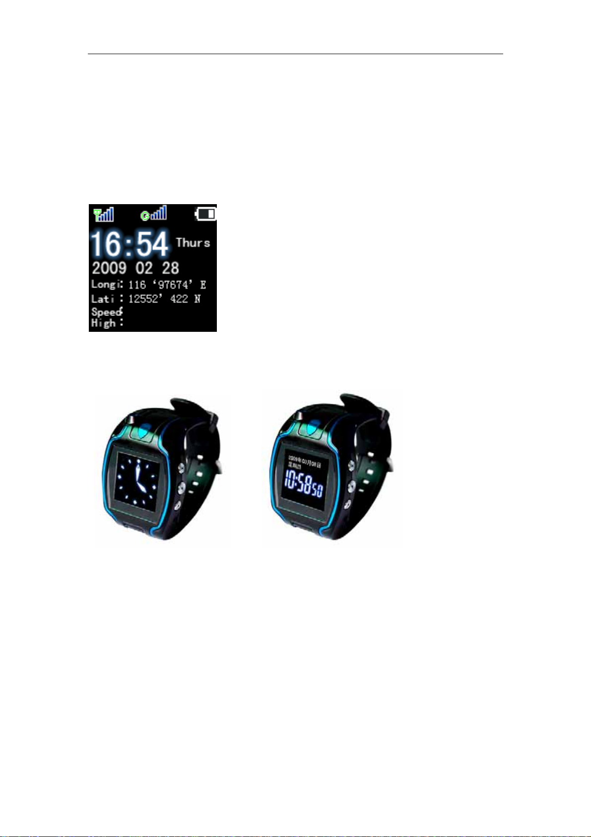
4.1 Interface Definition
The upper left Signal 1 on the latitude and longitude interface is GSM signal indication.
The upper left Signal 2 on the latitude and longitude interface is GPS signal indication.
Push the Shift key to shift between the analogue clock interface and the digital clock, as shown
below:
10
Table of contents
Other V-Sun GPS manuals

V-Sun
V-Sun TLT-3 User manual

V-Sun
V-Sun V690 User manual

V-Sun
V-Sun TLT-2K User manual

V-Sun
V-Sun TLT-2F User manual

V-Sun
V-Sun BTGP38 User manual

V-Sun
V-Sun V521 User manual

V-Sun
V-Sun TLT-2K Operating and maintenance instructions

V-Sun
V-Sun TLT-2K User manual

V-Sun
V-Sun TLT-1C User manual

V-Sun
V-Sun V3338 User manual


