4 Application Description
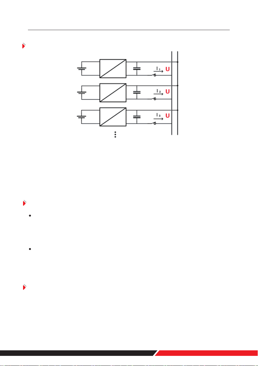
The battery packs support parallel connection, and synchronously increases the
backup time or backup power.
Confirm the consistency between the battery packs, check the SOC and voltage
and turn off the batteries before connecting them in parallel.
Multiple battery packs of parallel connection need to use RS485/CAN to
communicate, pay attention to the DIP switch settings.
4.2 Low-temperature Application
4.1 Parallel Connection Application
• Low-temperature Charging
The battery pack does not support direct charging of the battery below 0°C.
When the minimum temperature of the battery is below 0°C, the BMS will cut-off the
charging circuit and cannot be charged.
• Low-temperature Discharging
The battery pack does not support discharge below -20°C. When the minimum
temperature of battery is below -20°C, the BMS will cut-off the discharge circuit and
cannot discharge.
4.3 Low battery-capacity Storage (SOC≤5%)
After the battery pack is power off, there will be BMS static power consumption
and self-discharge loss. In actual scenarios, it is necessary to avoid low-battery-pow-
er state(SOC≤5%)storage. If it is unavoidable, the longest storage period is 30
5
1 Foreword.................................................................................................................................................
2 Safety........................................................................................................................................................
2.1 Safety Precautions......................................................................................................................
2.2 Abuse Operation.........................................................................................................................
3 Overview..................................................................................................................................................
3.1 Product Description...................................................................................................................
3.1.1 Features...............................................................................................................................
3.1.2 Basic Functions.................................................................................................................
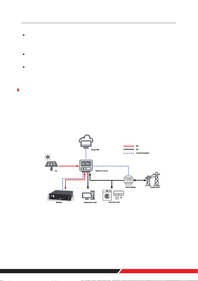
3.2 Application Scenario.................................................................................................................
4 Application Description.....................................................................................................................
4.1 Parallel Connection Application............................................................................................
4.2 Low-temperature Application................................................................................................
4.3 Low battery-capacity Storage (SOC≤5%)...........................................................................
4.4 Application of Nearing the Ocean.........................................................................................
5 Product Introduction..........................................................................................................................
5.1 Module Specification Parameter Introduction.................................................................
5.2 Panel Introduction......................................................................................................................
5.2.1 Panel Function...................................................................................................................
5.2.2 Indicator Description......................................................................................................
5.2.3 DIP Address........................................................................................................................
5.2.4 Communication Port Definition..................................................................................
5.2.5 Dry Contact Alarm Definition.......................................................................................
6 Installation..............................................................................................................................................
6.1 Tools Preparation........................................................................................................................
6.2 Unpacking and Inspection.......................................................................................................
6.3 Preparing for Installation.........................................................................................................
6.4 Installation....................................................................................................................................
6.5 Cable Connection.......................................................................................................................
7 Power On.................................................................................................................................................
7.1 Power-on Operation...................................................................................................................
7.2 Power System Parameter Setting...........................................................................................
8 Shipment & Maintenance & Storage...........................................................................................
8.1 Shipment.......................................................................................................................................
8.2 Maintenance................................................................................................................................
8.2.1 Battery Maintenance Considerations.......................................................................
8.2.2 Routine Maintenance.....................................................................................................
8.3 Battery Storage...........................................................................................................................
9 Trouble Shooting.................................................................................................................................
10 Warranty...............................................................................................................................................
11 Abbreviations.....................................................................................................................................