V-TAC V-T48160 User manual

V1.0
V-T48160
VTAC Volts
Instruction Manual


4.4.1 Single battery connection . . . . . . . . . . . . . . . . . . . . . . . . . . . . . . . . . . . . . . . . . . . . . . . . . . . . . . . . . . . . . . 13
6 Battery Monitoring . . . . . . . . . . . . . . . . . . . . . . . . . . . . . . . . . . . . . . . . 23
1.3 Electrical safety . . . . . . . . . . . . . . . . . . . . . . . . . . . . . . . . . . . . . . . . . . . . . . . . . . . . . . . . . . . . . . . . . . . . 4
4.2.2 CAN communication point definition . . . . . . . . . . . . . . . . . . . . . . . . . . . . . . . . . . . . . . . . . . . . . . . . . . 12
Catalog
1.1 General security . . . . . . . . . . . . . . . . . . . . . . . . . . . . . . . . . . . . . . . . . . . . . . . . . . . . . . . . . . . . . . . . . . . . 1
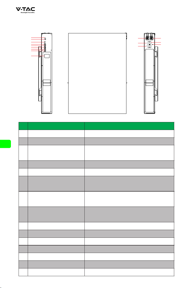
2.2 Appearance description . . . . . . . . . . . . . . . . . . . . . . . . . . . . . . . . . . . . . . . . . . . . . . . . . . . . . . . . . . . 6
3.3 Ladder use safety . . . . . . . . . . . . . . . . . . . . . . . . . . . . . . . . . . . . . . . . . . . . . . . . . . . . . . . . . . . . . . . . . 10
4.4.2 Multiple batteries in parallel . . . . . . . . . . . . . . . . . . . . . . . . . . . . . . . . . . . . . . . . . . . . . . . . . . . . . . . . . . . . 14
5.2 Battery function description . . . . . . . . . . . . . . . . . . . . . . . . . . . . . . . . . . . . . . . . . . . . . . . . . . . . . 15
5.2.3 RST key description . . . . . . . . . . . . . . . . . . . . . . . . . . . . . . . . . . . . . . . . . . . . . . . . . . . . . . . . . . . . . . . . . . . . . 18
5.2.4 Sleep and wake up . . . . . . . . . . . . . . . . . . . . . . . . . . . . . . . . . . . . . . . . . . . . . . . . . . . . . . . . . . . . . . . . . . . . . . 18
9 Warranty products . . . . . . . . . . . . . . . . . . . . . . . . . . . . . . . . . . . . . . . . 31
4.2.1 RS485 communication point definition . . . . . . . . . . . . . . . . . . . . . . . . . . . . . . . . . . . . . . . . . . . . . . . . 12
6.1 Software running environment . . . . . . . . . . . . . . . . . . . . . . . . . . . . . . . . . . . . . . . . . . . . . . . . . . . 23
3.2 Basic installation requirements . . . . . . . . . . . . . . . . . . . . . . . . . . . . . . . . . . . . . . . . . . . . . . . . . . . . 8
5.1 Check before power on . . . . . . . . . . . . . . . . . . . . . . . . . . . . . . . . . . . . . . . . . . . . . . . . . . . . . . . . . . . 15
4.4 Battery connection . . . . . . . . . . . . . . . . . . . . . . . . . . . . . . . . . . . . . . . . . . . . . . . . . . . . . . . . . . . . . . . 13
5.3 Wireless kit (optional) . . . . . . . . . . . . . . . . . . . . . . . . . . . . . . . . . . . . . . . . . . . . . . . . . . . . . . . . . . . . 20
3.6 Installation guidelines . . . . . . . . . . . . . . . . . . . . . . . . . . . . . . . . . . . . . . . . . . . . . . . . . . . . . . . . . . . . 10
4.2 communication line connection . . . . . . . . . . . . . . . . . . . . . . . . . . . . . . . . . . . . . . . . . . . . . . . . . . 12
2.3 System diagram . . . . . . . . . . . . . . . . . . . . . . . . . . . . . . . . . . . . . . . . . . . . . . . . . . . . . . . . . . . . . . . . . . . . 7
3.1 Unpacking inspection . . . . . . . . . . . . . . . . . . . . . . . . . . . . . . . . . . . . . . . . . . . . . . . . . . . . . . . . . . . . . . 8
4 Electrical connection . . . . . . . . . . . . . . . . . . . . . . . . . . . . . . . . . . . . . . 11
3.4 Drilling safety . . . . . . . . . . . . . . . . . . . . . . . . . . . . . . . . . . . . . . . . . . . . . . . . . . . . . . . . . . . . . . . . . . . . . 10
4.2.3 RS232 communication point definition . . . . . . . . . . . . . . . . . . . . . . . . . . . . . . . . . . . . . . . . . . . . . . . . 12
5.2.2 Screen . . . . . . . . . . . . . . . . . . . . . . . . . . . . . . . . . . . . . . . . . . . . . . . . . . . . . . . . . . . . . . . . . . . . . . . . . . . . . . . . . . . 16
4.3 System connection diagram . . . . . . . . . . . . . . . . . . . . . . . . . . . . . . . . . . . . . . . . . . . . . . . . . . . . . . 13
2.1 Product introduction . . . . . . . . . . . . . . . . . . . . . . . . . . . . . . . . . . . . . . . . . . . . . . . . . . . . . . . . . . . . . . 5
5 System tuning . . . . . . . . . . . . . . . . . . . . . . . . . . . . . . . . . . . . . . . . . . . . . 15
4.1 Cable connection . . . . . . . . . . . . . . . . . . . . . . . . . . . . . . . . . . . . . . . . . . . . . . . . . . . . . . . . . . . . . . . . . 11
1.2 Personnel requirements . . . . . . . . . . . . . . . . . . . . . . . . . . . . . . . . . . . . . . . . . . . . . . . . . . . . . . . . . . . 4
5.2.1 Buzzer action description . . . . . . . . . . . . . . . . . . . . . . . . . . . . . . . . . . . . . . . . . . . . . . . . . . . . . . . . . . . . . . . 15
1.Safety precautions . . . . . . . . . . . . . . . . . . . . . . . . . . . . . . . . . . . . . . . . . 1
2 Product introduction . . . . . . . . . . . . . . . . . . . . . . . . . . . . . . . . . . . . . . . 5
3 Product installation . . . . . . . . . . . . . . . . . . . . . . . . . . . . . . . . . . . . . . . . 8
3.5 Safety of handling heavy objects . . . . . . . . . . . . . . . . . . . . . . . . . . . . . . . . . . . . . . . . . . . . . . . . . 10
5.2.5 Indication description . . . . . . . . . . . . . . . . . . . . . . . . . . . . . . . . . . . . . . . . . . . . . . . . . . . . . . . . . . . . . . . . . . 19
6.3 Interface function . . . . . . . . . . . . . . . . . . . . . . . . . . . . . . . . . . . . . . . . . . . . . . . . . . . . . . . . . . . . . . . . 24
6.3.1 Real time monitoring . . . . . . . . . . . . . . . . . . . . . . . . . . . . . . . . . . . . . . . . . . . . . . . . . . . . . . . . . . . . . . . . . . . . 24
6.2 Connect the upper computer . . . . . . . . . . . . . . . . . . . . . . . . . . . . . . . . . . . . . . . . . . . . . . . . . . . . . 23
6.3.2 Parallel monitoring . . . . . . . . . . . . . . . . . . . . . . . . . . . . . . . . . . . . . . . . . . . . . . . . . . . . . . . . . . . . . . . . . . . . . . 26
6.3.3 Store information . . . . . . . . . . . . . . . . . . . . . . . . . . . . . . . . . . . . . . . . . . . . . . . . . . . . . . . . . . . . . . . . . . . . . . . . 26
6.3.4 Parameter setting . . . . . . . . . . . . . . . . . . . . . . . . . . . . . . . . . . . . . . . . . . . . . . . . . . . . . . . . . . . . . . . . . . . . . . . . 27
6.3.5 System setting . . . . . . . . . . . . . . . . . . . . . . . . . . . . . . . . . . . . . . . . . . . . . . . . . . . . . . . . . . . . . . . . . . . . . . . . . . . 28
6.3.6 Export data . . . . . . . . . . . . . . . . . . . . . . . . . . . . . . . . . . . . . . . . . . . . . . . . . . . . . . . . . . . . . . . . . . . . . . . . . . . . . . 28
6.4 Replacing inverter protocol(optional) . . . . . . . . . . . . . . . . . . . . . . . . . . . . . . . . . . . . . . . . . . . 29
7 Maintenance and requirements . . . . . . . . . . . . . . . . . . . . . . . . . . . . 30
8 Battery storage requirements . . . . . . . . . . . . . . . . . . . . . . . . . . . . . . 30
10 Exemption from liability . . . . . . . . . . . . . . . . . . . . . . . . . . . . . . . . . . 31

1.Safety precautions
1.1 General security
Statement
When installing, operating and maintaining the equipment, please read this manual
first and follow the signs on the equipment and all safety precautions .
The “notice", "attention", "warning" and "danger" in the manual do not represent all
safety precautions to be observed, but only supplement all safety precautions. The
company shall not be liable for any violation of general safety operation requirements
or safety standards for design, production and use of equipment.
The equipment shall be used in an environment that meets the requirements of design
specifications, otherwise it may cause equipment failure, and the resulting equipment
function abnormalities or component damage, personal safety accidents, property
losses, etc. are not within the scope of equipment quality assurance. The installation,
operation and maintenance of the equipment shall comply with local laws, regulations
and specifications. The safety precautions in the manual are only a supplement to local
laws, regulations and specifications.
The company shall not be liable for any of the following circumstances.
◆ Do not operate under the ser vice conditions described in this manual.
◆ The installation and use environment exceeds the provisions of relevant
international or national standards.
◆ Disassemble, change the product or modify the software code
without authorization.
◆ Failure to follow the operation instructions and safety warnings in the product
and documents.
◆ Transportation damage caused by customer's own transportation.
◆ Damage caused by storage conditions not meeting the requirements
of product documents.
General requirements
Live operation is strictly prohibited during installation.
◆ It is strictly prohibited to install, use and operate outdoor equipment and cables
(including but not limited to handling equipment, operating equipment and
cables, plug and unplug signal interfaces connected to outdoor, high-altitude
operation, outdoor installation, etc.) in severe weather such as lightning, rain,
snow and force gale.
◆ After installing the equipment, the empty packaging materials such as cartons, foam,
plastic, tie line should be removed.
◆ In case of fire, evacuate the building or equipment area and press the fire alarm bell
or dial the fire alarm telephone. Under no circumstances shall re-enter the burning
building.
◆ It is strictly prohibited to artificially alter, damage or block the identification and
nameplate on the equipment.
DANGER
1

◆ When installing the equipment, use tools to tighten the screws.
◆ Paint scratches during equipment transportation and installation must be repaired
in time. It is strictly prohibited to expose the scratched parts to the outdoor
environment for a long time.
◆ Do not open the main panel of the device without the permission of the
manufacturer.
◆ In any case, do not change the structure and installation sequence of the equipment
without the permission of the manufacturer.
◆ It is forbidden to affect the battery terminal components during handling, and it is
not allowed to lift and handle through the battery terminal bolts.
◆ It is not allowed to reverse engineer, decompile, disassemble, adapt, implant or other
derivative operations on the equipment software, and it is not allowed to study the
internal implementation of the equipment in any way.
Personal safety
◆ Wear appropriate personal protective equipment during equipment operation. In
case of any fault that may cause personal injury or equipment damage, the
operation shall be terminated immediately, the person in charge shall be reported,
and effective protective measures shall be taken.
◆ Before using the tool, please master the correct use method of the tool to avoid
personal injury and equipment damage.
◆ When the equipment is running, the shell temperature is high and there is a risk of
burns. Do not touch it.
◆ In case of battery failure, the temperature may exceed the burn threshold of the
touchable surface, and contact should be avoided.
◆ Do not open or damage the battery. The released electrolyte is harmful to the skin
and eyes. Avoid contact.
◆ Do not place irrelevant items on the top of the equipment or insert them anywhere in
the equipment.
◆ Do not place inflammables around the equipment.
◆ The battery shall not be placed in the fire to avoid explosion and endanger personal
safety.
◆ Do not place the battery module in water or other liquids.
◆ Do not short-circuit the battery terminal, which may cause combustion.
◆ The battery may cause the danger of electric shock and large
short-circuit current. When using the battery, pay attention to the following
precautions :
a) Remove watches, rings or other metal objects.
b) Tools using insulated handles .
c) Wear rubber gloves and boots .
d) Do not place tools or metal parts on the top of the battery .
e) Disconnect the charging power supply before connecting or disconnecting the
battery terminal.
◆ Do not use water or detergent to clean the electrical parts inside and outside the
cabinet.
2

◆ Do not stand or lean on or sit on the equipment.
◆ Do not damage each module of the equipment.
◆ When installing the battery module, if the battery module falls or is strongly
impacted, the equipment will be damaged. It is strictly prohibited to continue to
use, otherwise there will be safety risks (cell leakage, electric shock injury, etc.).
Treatment measures for battery leakage
In case of electrolyte leakage, avoid contact with leaked liquid or gas.
Electrolyte is corrosive and contact may cause skin irritation and chemical burns.
In case of contact with battery electrolyte, the following measures shall be taken.
Inhalation: evacuate the contaminated area, enter fresh air immediately, and seek
medical help immediately.
Eye contact: immediately flush eyes with plenty of water for at least 15 minutes, do
not rub, and seek medical help immediately.
Skin contact: immediately wash the contact area with plenty of water and soap and
seek medical help immediately.
Ingestion: seek medical help immediately.
Fire treatment measures
◆ In case of fire, the system should be powered off under the condition of ensuring
safety.
◆ Use carbon dioxide, FM-200 or ABC dry powder fire extinguisher to extinguish the
fire.
When the battery temperature is too high, it will cause battery deformation, damage,
electrolyte overflow and toxic gas leakage. Please keep away from it to avoid skin
irritation and chemical burns.
DANGER
◆ Power down the system to ensure personal safety.
◆ If any part of the battery is flooded, do not touch the battery to avoid electric shock.
◆ Do not use the flooded battery. Contact the battery recycling company for
scrapping.
Flood emergency measures
Battery recycling
◆ Please dispose of waste batteries according to local laws and
regulations. Do not treat batteries as domestic waste.
◆ If the battery leaks or bulges, please contact technical support or
battery recycling company for scrapping.
◆ When the battery is unavailable beyond its ser vice life, please contact
the battery recycling company for scrapping.
◆ Avoid exposing the battery to high temperature or direct sunlight.
◆ Avoid exposing the battery to high humidity or corrosive environment.
3

1.2 Personnel requirements
◆ The personnel responsible for the installation and maintenance of this equipment
must understand various safety precautions and master the correct operation
methods.
◆ Only qualified professionals or trained personnel are allowed to install, operate and
maintain the equipment.
◆ Only qualified professionals are allowed to dismantle safety facilities and overhaul
equipment.
◆ Personnel operating the equipment, including operators, trained personnel and
professionals, shall have the special operation qualification required by the local
state.
◆ The replacement of equipment or components (including software) must be
completed by professionals or authorized personnel.
◆ Professionals: those who have training or experience in operating equipment and
can understand the potential sources and magnitude of hazards in the process of
equipment installation, operation and maintenance.
◆ Trained personnel: personnel who have received corresponding technical training
and have necessary experience, can be aware of the risks that may be brought to
him during a certain operation, and can take measures to minimize the risks to
himself or other personnel.
◆ Operators: operators who may come into contact with the equipment other than
trained personnel and professionals.
Explanation
Before making electrical connection, please ensure that the equipment is not damaged,
otherwise electric shock or fire may be caused.
General requirements
1.3 Electrical safety
◆ All electrical connections must meet the national electrical standards.
◆ The cable provided by the user shall meet the requirements of local laws and
regulations.
◆ Use special insulating tools for high voltage operation.
DC operation
It is forbidden to install or remove the power line with electricity. When the power cord
contacts the conductor, it will produce arc or electric spark, which can lead to fire or
personal injury.
◆ Before the electrical connection of the equipment, if the live parts may be touched, the
corresponding breaking device at the front level of the equipment must be
disconnected.
◆ Before connecting the power cord, confirm that the label identification of the power
cord is correct before connecting.
DANGER
DANGER
4

◆ If the equipment has multiple inputs, all inputs of the equipment shall be
disconnected, and the equipment can be operated only after the equipment is
completely powered off.
Wiring requirements
◆ The use of the cable in high temperature environment may cause aging and damage
of the insulating layer. The distance between the cable and the periphery of the
heating device or heat source area shall be at least 30mm.
◆ Similar cables shall be bound together, and different types of cables shall be laid at
least 30mm apart. Mutual winding or cross laying is prohibited.
◆ The cables used must be firmly connected, well insulated and of appropriate
specifications.
2.Product introduction
2.1 Product introduction
Function
Li-ion battery includes only battery modules, which can store
and release electric energy according to the requirements of inverter management
system. The input and output ports of battery are 48 / 51.2V DC.
◆ Battery charging: the power control module is connected with the energy storage
terminals (BAT +, bat -) of the inverter to charge the battery and store the excess
photovoltaic energy in the battery under the control of the inverter.
◆ Battery discharge: when the photovoltaic energy is insufficient to supply power to the
load, the system needs to control the battery to supply power to the load and output
the stored battery energy to the load through the inverter.
Model
NO.Voltage ESI
Capacity IP Level
148V IP20
Bluetooth
WIFI
GSM
160/220Ah
5

2.2 Appearance description
6
1
2
3
4
5
6
7
8
9 10
11
12
13
14
15
NO. Description Functional Description
1
3
4
5
6
2
Battery- Negetive terminal
Battery+ Positive terminal
Reset key On/OFF button
ADS Dialer Display connection address
RS485 RS485 communication interface
CAN CAN communication interface
DO
1/2 Normally open, closed during fault
protection 3/4 Normally open, closed when a
low battery alarm signal has occurred
RS232 RS232 communication interface
(for battery condition monitoring)
RS485 communication interface (Used in
communication parallel,and for battery condition
monitoring or manufacturer to debug or ser vice)
RS485 communication interface (Used in
communication parallel,and for battery condition
monitoring or manufacturer to debug or ser vice)
ESI Expand Bluetooth / WiFi / GSM functions
Ground wire Battery ground wire
RS485
RS485
7
8
9
10
11
12
ALM Alarm and protection
14
RUN Work
13
HMI Display battery status information
15

2.3 System diagram
(A) PV module
(D) AC switch
(F) Intelligent power collector
(I) GSM
(L) Bluetooth
(B) DC switch
(E) Power Distribution Box
(G) Power grid
(J) WIFI
(M) APP
( C) Inverter
(H) Battery(WALL)
(K) Router
(N) Load
◆ The input and output of the battery energy storage system are connected to the energy
storage port of the inverter.
◆ Following are the modes to communicate with the battery energy storage system:
• The Inverter can be connected through CAN interface to realize the communication
and control between the inverter and battery.
• The battery can be accessed directly through the mobile phone Bluetooth app to
view, manage and maintain the performance.
• The battery can be accessed from the public network through WiFi interface to
view, manage and maintain the performance.
• The battery can be accessed from the public network through GSM interface to view,
manage and maintain the performance.
Explanation
7

3.Product installation
3.1 Unpacking inspection
Please confirm whether the outer package of the product is damaged before unpacking.
After unpacking, please carefully check the product for damage or missing accessories.
In case of damage or missing accessories, please contact the supplier directly for
assistance.
NO. QTY Description
A
B
C
D
E
F
G
H
1
1
6
1
1
1
n
n
Battery PACK
Instructions
Expansion screws M10
MSDS Transportation certificate
RS232 communication line
Power line 1m
Parallel line:Customized according to customers
RS485 communication line: Customized according to customers
3.2 Basic installation requirements
◆ Shall be installed in a dry and well-ventilated area to ensure good heat dissipation.
◆ Recommended to choose a sheltered installation site or under a sunshed, indoor is
more preferable option.
◆ Avoid direct sunlight or rain. The surrounding environment should be clean and free
from large infrared radiation, organic solvents and corrosive gases.
F
BC
MSDS
D EA
8

◆ The installation location shall be reasonably away from the fire source.
◆ The installation location shall not be accessible by the children.
◆ The installation location shall be sufficiently away from water sources, such as water
tap, sewer pipe, sprinkler etc., to avoid water infiltration.
◆ The installation wall shall be strong enough to carry the weight of the battery for a
long time, please follow local standard or best practice guidelines.
◆ Do not place inflammables and explosives around the battery.
◆ When the battery is running, do not block the vent or cooling system. Maintain the
battery operating temperature for charging 0-55°C and discharging - 20 ~ 60°C.
◆ Do not store or install the battery in an environment of flammable or explosive gas or
smoke. Any operation of the battery in such environment is strictly prohibited.
◆ The battery can be installed on a vertical or backward inclined plane. Please refer to the
following figure:
◆ In order to ensure good heat dissipation and convenience in operation and
maintenance, sufficient clearance shall be reser ved while installing the battery. An example
of such clearances are shown in the figure below. Please strictly follow the local battery
installation guidelines, where applicable.
ESI
+
-
ESI
+
-
ESI
+
-
ESI
+
-
ESI
+
-
30cm 30 cm
30cm
30c m
9

3.3 Ladder use safety
◆ Wooden ladder or FRP ladder shall be used when power climbing operation may be
involved.
◆ When using the herringbone ladder, the pulling rope must be firm, and someone
must hold the ladder during operation.
◆ Before using the ladder, please confirm that the ladder is intact, the bearing weight of
the ladder meets the requirements, and overweight is strictly prohibited.
◆ When using the ladder, the wide foot of the ladder shall face down or protective
measures shall be taken at the bottom of the ladder to prevent slipping.
◆ The ladder should be placed in a stable place. The gradient of the ladder should be
75 °, which can be measured with an angle ruler, as shown in the figure below.
◆ When climbing the ladder, please pay attention to the
following actions to reduce danger and ensure safety:
◆ Keep your body steady.
◆ The maximum height of operators standing on
their feet shall not exceed the fourth step of the
ladder from top to bottom.
◆ Ensure that the center of gravity of the body does
not deviate from the edge of the ladder.
3.4 Drilling safety
The following safety precautions shall be considered when drilling on the wall and
ground:
◆ Wear goggles and protective gloves when drilling.
◆ During drilling, the equipment shall be covered to prevent debris from falling into the
equipment. After drilling, the debris shall be cleaned.
3.5 Safety of handling heavy objects
◆ When carrying heavy objects, be prepared to bear the load to avoid being crushed or
sprained by the heavy objects.
◆ When handling the equipment by hand, wear protective gloves to avoid injur y.
3.6 Installation guidelines
◆ Determine the exact location of battery installation; If it is wall mounted, the wall
thickness shall be greater than or equal to 100mm;
◆ Use the mounting bracket or cardboard to determine the specific location of the hole;
Keep the top edge of the cardboard horizontal.
◆ Drill 6 holes at the marked position with the hole diameter of φ 8;The hole depth shall
not be less than 55mm.
◆ Knock 6 expansion screws into the drilled holes.
◆ Hang the battery mounting bracket on the screw.
10

◆ Lock the nut and fix the battery mounting bracket. Then hang the battery on the
mounting bracket.
◆ After adjusting the position of the battery, lock the M6 * 40 screw at the top of the
support, fix the battery, and place the battery to slide.
◆ installation is complete.
4.1 Cable connection
4.Electrical connection
Anderson connector is used on the DC input side of the battery energy storage system.
The specific connections are as follows:
B
A
30c m 30c m
30c m
30c m
11

NO.
A
B
Description
Terminal Cable
diameter Length
Anderson/SC25-8
Anderson
25mm²
25mm² 1-3m
1-3m Used for connection between
battery and inverter
For battery parallel connection
◆ RS232 communication: BMS can communicate with the computer through RS232
interface to check battery health related information including
battery voltage, current, temperature, and manufacturer’s
default data.
◆ RS485 / can communication: CAN communication connects the battery with the inverter
to function as duo for operations.
◆ RS485 communication: The additional two RS485 interfaces can be used for parallel
connections with other batteries, or, to monitor battery health
conditions including debugging and routine servicing.
Addresses PIN: 1-15
Explanation
4.2 Communication line connection
4.2.1 RJ45 Communication point definition(8P8C)
123 4 56 7 8
4.2.2 RJ11 Communication point definition(6P6C)
123 4 56
PIN
1
2
3
4
5
6
Rs232
NC
TX
RX
GND
NC
NC
PIN
1
2
3
4
5
6
7
8
RS485 CAN
RS485_A NC
GND NC
NC CANL
NC CANH
GND NC
RS485_A GND
RS485_B NC
RS485_B NC
12

◆ Different inverter communication protocols have different pin definitions. Please pay
attention to the compatibility between the battery and inverter CAN/RS485
communication line.
4.3 System connection diagram
Cable color Description Cable color Description
DC positive wire
DC negative wire
Ground wire
Live Wire
Naught wire
Communication line
4.4 battery connection
4.4.1 Single battery connection
PV
PV+ N GND LB AT+
RS4 85 OR
CAN
AC_OU T AC_ IN BAT
NGND L
INVERTER Battery
PC
RST
ADS
DO
RS485
CAN
RS232
RS485
13
PV
PV+ P V- N GN D LBAT+ BAT-
RS48 5 OR
CAN
AC_ OUT A C_I N BAT
BAT+ RS4 85 OR CAN
NGND L
PV combiner b ox
PV
INVERTER
LOAD
POWER GRID
GND
DC Breaker
AC Breaker
AC Breaker
AC Breaker

4.4.2 Multiple batteries in parallel
Cable color Description Cable color Description
DC positive wire
DC negative wire RJ11 Communication Line
RJ45 Communication Line
RS485/CAN communication
Cable color Description Cable color Description
DC positive wire
DC negative wire
RJ45 Communication Line
RS485/CAN communication
Parallel Communication line
RJ11 Communication Line
The power lines between each battery are the same length
◆ The maximum number of batteries can only be connected in parallel is 15pcs.
After parallel connection, the address of ads needs to be assigned,
as shown below:
Address
2
3
4
5
6
7
8
9
10
11
12
13
1
0
14
15
Dial switch Remark
#1 #2 #3 #4
OFF OFF OFF OFF
ON OFF OFF OFF
OFF ON OFF OFF
ON ON OFF OFF
OFF OFF ON OFF
ON OFF ON OFF
OFF ON ON OFF
ON ON ON OFF
OFF OFF OFF ON
ON OFF OFF ON
OFF ON OFF ON
ON ON OFF ON
OFF OFF ON ON
ON OFF ON ON
OFF ON ON ON
ON ON ON ON
Battery PACK1(Main PACK)
Battery PACK2
Battery PACK3
Battery PACK4
Battery PACK5
Battery PACK6
Battery PACK7
Battery PACK8
Battery PACK9
Battery PACK10
Battery PACK11
Battery PACK12
Battery PACK13
Battery PACK14
Battery PACK15
Explanation
PV
PV+ N GND LB AT+
RS4 85 OR
CAN
AC_OU T AC_ IN BAT
NGND L
INVERTER
Battery-1
PC
RST
ADS
DO
RS485
CAN
RS232
RS485
RST
ADS
DO
RS485
CAN
RS232
RS485
Battery-2
14

◆ The inverter only needs to communicate with the host (Pack1).
◆ When multiple batteries are connected with multiple inverters, it is best to connect
through the combiner box. If it is not connected through the combiner box, the
wiring mode shall be confirmed with the manufacturer's agent. And the cable from
each battery to the inverter remains the same length.
◆ Batteries are not allowed to be connected in series.
◆ Different batteries with different chemistries, different batches of batteries from the
same chemistry and technical design parameters can not be bundled and used
together.
Notice
5.System tuning
5.1 Check before power on
NO.
1
2
3
4
5
6
7
8
Inspection items Acceptance criteria
The energy storage battery is
installed in place
Reasonable cable layout
Beautiful binding of cable ties
Reliable grounding
Disconnect switch
The cable is connected in place
Insulate unused terminals and interfaces
The installation environment meets
the requirements
The installation is correct, firm
and reliable.
The cable layout is reasonable to meet
the user's requirements.
The cable ties shall be uniform and no
sharp corners shall be left at the cut.
The ground wire is connected correctly,
firmly and reliably.
"DC switch" and all switches connected
to energy storage are in "off" state.
The DC input line, energy storage line
and signal line are connected correctly,
firmly and reliably.
Install insulating tape on unused
terminals and interfaces.
The installation space is reasonable, the
environment is clean and tidy, and there
is no construction residue.
After the inspection, press and hold the RST key (3 ~ 6S) and release it, the protection
board is activated.
5.2 Battery function description
5.2.1 Buzzer action description
NO. Mode Description
1
2
Fault
Protection
Beep 0.25S every 1S
Beep 0.25S every 2S (except over voltage protection)
Beep 0.25S every 3S (except over voltage alarm)
3Alarm
The buzzer function can be enabled or disabled by the upper computer.
It is disabled by default.
Explanation
15

5.2.2 Screen
HMI screen composition
Home:
Battery Information:
NO. NO.
Items Description Items Description
1
2
3
4
5
6
7
Addr.
Rem Cap
Tol Cap
Temp1~4
Environment temperature
MOS Temperature
Battery Cell Voltage
Battery Pack Address
Remnant capacity
Total capacity
Battery Temperature
Env Temp
MOS Temp
Cells1~16
2
3
4
5
6
1
NO. ICON Description
0%<SOC<25%
25%=SOC<50%
50%=SOC<75%
75%=SOC=100%
SOC=0%
Battery Alarm Status
16
Other manuals for V-T48160
1
Table of contents
Other V-TAC Camera Accessories manuals