VACGEN WS Series Manual

Page 1 of 13
[email protected] www.vacgen.com +44 (0) 1424 836 333
Operating and Maintenance Handbook
WS SERIES WOBBLE STICKS
Copyright Notice 2002 by VACGEN. All rights reserved. Information contained in this handbook is
subject to change without notice and does not represent a commitment on the part of VACGEN. No
part of this document may be copied or distributed, transmitted, transcribed, stored in a retrieval
system or translated into any human or computer language, in any form or by any means, electronic,
mechanical, magnetic, optical, manual or otherwise or disclosed to third parties without the express
written permission of VACGEN, Maunsell Road, Castleham Industrial Estate, St, Leonards on Sea,
East Sussex, TN38 9NN, UK
REVISION
DATE
COMMENTS
INITIALS
1
Jan 1996
Original release
MJD

Page 2 of 13
[email protected] www.vacgen.com +44 (0) 1424 836 333
Contents
1.0 Introduction .................................................................................... 1
2.0 Specification ..................................................................................1
3.0 Installation and Use of Conventional / Universal Wobble Sticks 2
4.0 Construction ...................................................................................2
4.1 Transfer Fork ................................................................................ 3
4.2 Retractor Cradle ........................................................................... 3
5.0 Pincer Grip Wobble Sticks ......................................................... 3
5.1 Construction ..................................... 3
5.2 Preperation ............................................................... 4
5.3 Installation ......................................................... 3
5.4 Operation ..................................... 3
5.5 Bakeout ............................................................... 4
5.6 Maintenance ......................................................... 3
5.7 The Cassette Accessory ..................................... 3
6.0 Spares and Accessories ...................................................... 4

Page 3 of 13
[email protected] www.vacgen.com +44 (0) 1424 836 333
WARRANTY
1. Subject to fair wear and tear and the due, observance of any installation user, storage, operating or
maintenance instructions the Seller undertakes to replace or, at its option repair free of charge to the
purchaser, any goods which the purchaser can establish are defective by reason of defective
workmanship or materials which are returned to the Seller, carriage paid, within 12 months of the date
of dispatch by the Seller. In the event, however, that the Seller supplies spare parts either direct, or
that are fitted or installed or replaced by the Sellers' service center such spare parts will be subject to
a warranty period of six months only.
2. The Purchaser cannot return any product for warranty repair without the prior approval of VACGEN
and the issue of a Goods Return Number (GRN). This shall be obtained by contacting the service
center at VACGEN. All returned products must be accompanied by a completed Declaration of
Contamination form. Customers must, in the first instance, contact the local selling agent.
3. We reserve the right to decline to service equipment, we consider is in any way hazardous until a
clearance or safety certificate, in a form satisfactory to VACGEN, has been completed and returned
by the customer.
REPAIR
The following additional terms and conditions apply in the event that the customer elects to use the
services of VACGEN workshop on a chargeable basis.
1. At its own cost the customer shall dispatch the equipment to the workshop, carriage paid, suitably
packaged, protected and insured, bearing, a Goods Return Number (GRN)and a completed
Declaration of Contamination certificate obtained from VACGEN in advance of shipment.
2. During the period that the equipment is on VACGEN premises, VACGEN will insure the equipment
against all risks.
3. Vacuum Generator will provide an acknowledgement of the receipt together with an estimate of the
repair charges. Such estimates are carried out on a visual basis and are therefore intended as a
guide only. Formal fixed price repair quotations are available and involve the disassembly of the
equipment to determine the full extent of
the work necessary to restore the equipment to an acceptable standard. In the event that the
customer chooses not to proceed with the repair VACGEN will make a charge to cover this
examination effort.
Note:
The above are extracts from VACGEN Conditions of sale. Complete copies can be obtained from:
VACGEN, Maunsell Road, Castleham Industrial Estate St. Leonards on Sea, East Sussex, TN38
9NN, United Kingdom.

Page 4 of 13
[email protected] www.vacgen.com +44 (0) 1424 836 333
1.0 Introduction
Wobble sticks are devices that enable relatively simple movements to be transmitted through the wall
of a vacuum chamber. Wobble sticks can be used as sample transfer devices; they are located at
interchange points in the system where specimens must be moved from one device to the next (for
example, from a loadlock insertion probe to a sample manipulator). Wobble sticks may also be used
as actuators to operate mechanisms in vacuum such as shutters etc.
There are three distinct type of wobble stick device:
'Conventional' wobble sticks employ a single bellows and plunger mechanism (WS20) and have
limited angular and linear motions.
‘Universal' wobble sticks employ a double bellows and plunger arrangement which permits a much
wider range of angular and linear travel (WS50/120/182/240). These are often used with a particular
design of sample transfer arrangement to lift and carry samples within the vacuum system.
Accessories are available for these wobble sticks which allow a sample transfer system to be
designed around a standard transferable sample stub.
'Double Acting' devices incorporate, in addition to the double bellows arrangement, a third bellows
mechanism with a coaxial actuator. This arrangement (WS75/130PG) allows the wobble stick to be
fitted with a device which can firmly grip samples which minimises the danger of samples being
dropped during transfer.
2.0 Specifications
Wobble Stick Type Linear Movement Angular Movement
WS20 Conventional 20mm +7.5o
WS50 Universal 50mm +22o
WS120 Universal 120mm +22o
WS182 Universal 182mm +22o
WS240 Universal 240mm +22o
WS75PG Double Acting 75mm +22o
Pincer Grip
WS130PG Double Acting 130mm +22o
Pincer Grip
Mounting Flange: 70mm OD
Bakeout Temperature: 250oC Maximum

Page 5 of 13
[email protected] www.vacgen.com +44 (0) 1424 836 333
3.0 Installation and Use of Conventional/Universal Wobble Sticks
In order to be able to use the maximum available angular movement, the wobble stick should be
installed in a suitable 41 mm ID port which has a maximum length of 40mm from the flange face to
the inner wall of the chamber. The user must ensure that the bellows are not damaged in any way by
driving them into the port tabulation or chamber wall when operating the device. It is equally important
not to apply any twisting forces to the bellows during operation.
4.0 Construction
Wobble sticks are very simple devices and should not require any routine maintenance; an occasional
check should be made that the push rod has not unscrewed. If the smooth sliding action of the push
rod becomes more difficult to operate, the rod should be re-lubricated with a MoS2spray such as
Rocol DFSM (see section 5.6).

Page 6 of 13
[email protected] www.vacgen.com +44 (0) 1424 836 333
4.1 Transfer Fork
Two lengths of transfer fork are available for attachment to the WS50/120/182/240 wobble sticks.
These forks (see figure 3) are designed for transfer systems which employ the standard VACGEN
ESCA sample stubs. The transfer forks incorporate a locking spring which prevents samples being
dropped from the fork during transfer. The fork is held in place by means of the grub screws in the
end of the wobble stick.
4.2 Retractor Cradle
Standard wobble sticks have a parking plate which is designed to 'lock’ the wobble stick motion when
the device is not being used. The parking plate locks over the wobble stick shaft and prevents the
wobble stick being 'sucked' into the vacuum chamber under the action of external atmospheric
pressure. Some transfer applications require that the wobble stick be 'parked' in such a manner that it
is fully withdrawn from the vacuum chamber. If this is the case a retractor cradle (see figure 4) should
be fitted; this cradle holds the wobble stick in the fully withdrawn position when it is not in use. The
cradle is simply attached to the bolts on the wobble stick mounting flange; the parking plate and
parking plate bush should be removed when fitting the cradle assembly.
Figure 3 - Sample transfer forks Figure 4 -Retractor cradles

Page 7 of 13
[email protected] www.vacgen.com +44 (0) 1424 836 333
5.0 Pincer Grip Wobble Sticks
Pincer grip wobble sticks are intended for 'in-vacuum' handle' and transfer of specimens (see figure
5). The pincer grip is designed to handle specimens between 11mm and 14mm in diameter by 0.5mm
to 1.2mm thick. It is removable, as an assembly, from the wobble stick, thus offering the possibility of
alternate grips or end fittings being used.
Figure 5 - The WS75/130 wobble sticks
A cassette capable of holding up to 11 un-mounted specimens is available for use with pincer grip
wobble sticks (see section 5.7 and figure 6), thus permitting the bulk handling and movement of
specimens within the vacuum system. The twelfth station of the cassette is fitted with a 'gripping post'
to enable the loaded cassette to be handled by the pincer grip.

Page 8 of 13
[email protected] www.vacgen.com +44 (0) 1424 836 333
5.1 Construction
The construction is based on the standard double bellows universal type wobble stick to which an
additional co-axial bellows has been added. The movement of this third bellows is used to operate the
jaws of the pincer grip, the motion being transmitted along the axis of the wobble stick by means of a
push rod. The jaws of the pincer grip are closed by the action of two springs. One of these acts
directly on the jaws; the other retracts the push rod and resists the effect of atmospheric pressure
acting inside the bellows.
The opening of the jaws can be adjusted to some extent, and the whole pincer grip can be rotated
about the main axis. It is fitted with detents at 90ointervals thus enabling the plane of the specimen to
be varied. The rotation is accomplished by bringing the projecting upper part of the jaw assembly into
contact with a suitably positioned fixed finger or post; the application of a force sufficient to overcome
the spring-loaded detent will allow the jaw assembly to rotate to the desired position.
5.2 Preparation
The only preparatory work required is to ensure that the specimen is firmly held by the jaws of the
pincer grip and that a suitable, but not excessive, degree of opening is achieved. The opening of the
jaws is controlled by the adjusting screw in the moving jaw. The adjustment should be such that the
specimen is firmly gripped and registered in the segmental recess in the jaws. Too large an opening,
especially with a thin specimen, can result in the specimen being able to enter too deeply between the
jaws which may result in a fragile specimen being damaged.
If it is desired to use the rotational facility of the pincer, the suitability of the setting of the spring
pressure on the detent should be checked by a trial rotation. The setting should be such as to give a
positive location whilst at the same time allow the jaws to be rotated without the application of
excessive force. Adjustment of the detent spring pressure is achieved by means of the set screw and
locknut located at the top of the jaw assembly.
It is also necessary to correctly orient the cassette capstan post (stub) so that the specimen is aligned
in a plane parallel to the axis of the wobble stick. This must of course be done prior to evacuation of
the system, and after the pincer grip wobble stick has been installed. If the plane of the specimen is
not properly aligned, the removal and replacement of the specimens in the cassette will be made
more difficult and specimens may be dropped. It is recommended that provision is made to catch any
specimens that may be dropped, especially when retrieval is difficult, or problems could be caused
(e.g. if specimens were dropped onto a gate valve, or into a pump).

Page 9 of 13
[email protected] www.vacgen.com +44 (0) 1424 836 333
5.3 Installation
To obtain the full angular movement of the wobble stick it is necessary that the bore of the tabulation
to which it is attached should, ideally, be 41mm (not less than 38.5mm) in diameter.
The rotational orientation chosen is normally determined by the most convenient parking position and
by the required orientation of the specimen.
5.4 Operation
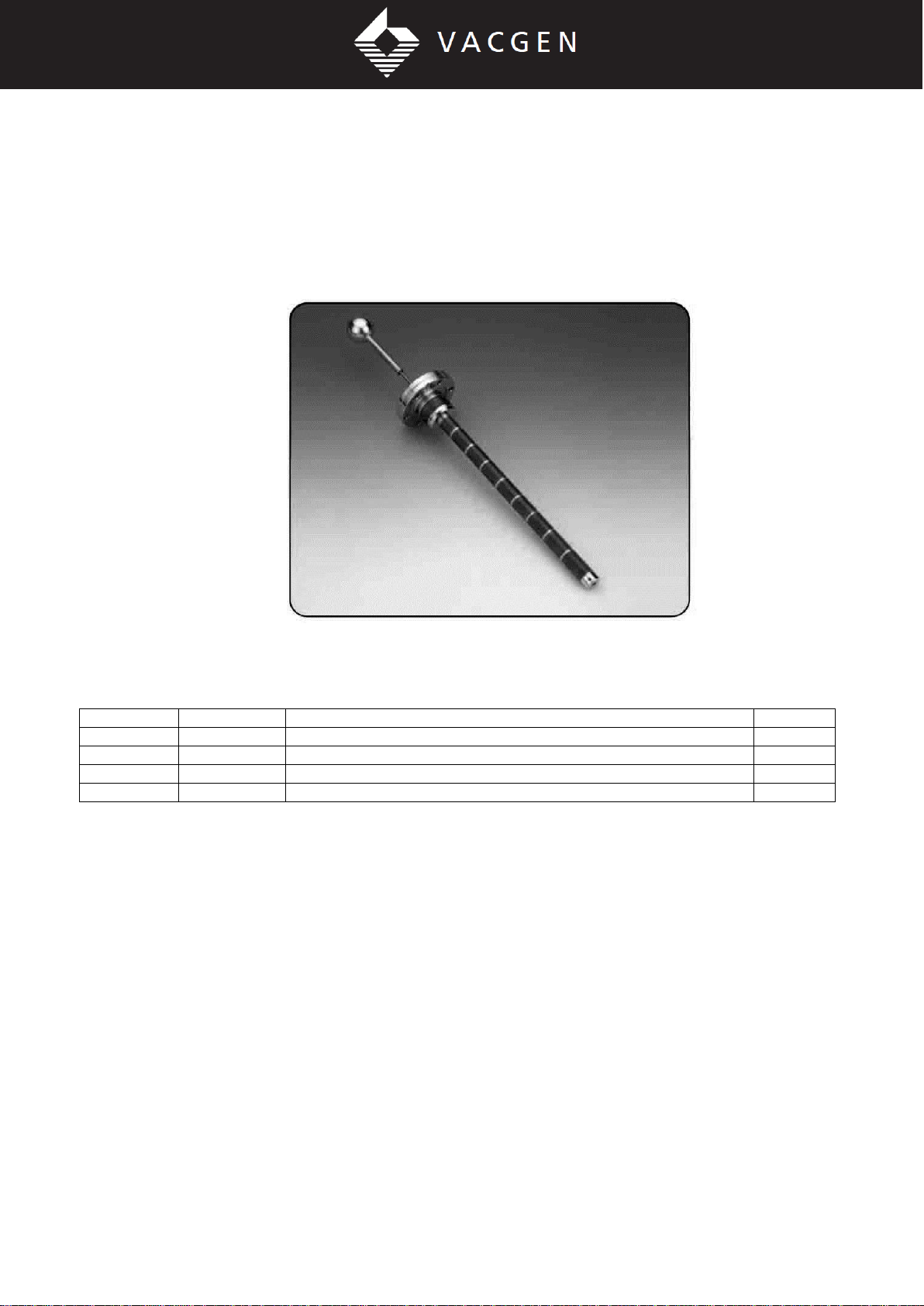
The pincer grip wobble stick has been designed for use with a cassette, and with certain of the
standard VACGEN accessories, principally the model HST non-inductive resistive heater and model
EBH electron beam heater. Both of these heaters can also be used for combination heating and
cooling and both are suitable for 'in-vacuum' attachment and removal of specimens using the pincer
grip device. A typical mode of operation would be as follows:
1) The cassette with the desired number of specimens would be placed on a transporter either in an
entry lock, or preparation chamber, which would then be evacuated.
2) The transporter would then move the cassette to the next stage where it would either be
transferred to the next transporter (if initially placed in an entry lock) or onto a parking position (in the
main analysis chamber), by the wobble stick.
3) Assuming the cassette is parked in the main chamber (the parking position must of course be such
that it is accessible to the pincer grip wobble stick), the nose of the pincer grip can be used to index
the cassette to bring the required specimen into alignment with the pincer grip jaws. The stub on
which the cassette is mounted has a 12 position capstan which engages with a spring-loaded detent
incorporated in the cassette. The cassette also has 6 slots on the periphery into which the nose of the
pincer grip jaws can be engaged when it is desired to index the cassette.
4) Open the jaws of the pincer grip. Engage and grip the specimen by releasing the plunger button.
Carefully retract the wobble stick removing the specimen from the cassette.
5) Align the face of the heater platten by rotation of the primary axis of the manipulator rotary drive so
that it is parallel with the rear face of the specimen. Insert the specimen under the spring clips (which
should previously have been adjusted to suit the thickness of the specimen being used), and gently
slide the specimen further under the spring clips. Now release the grip and use the end of the (closed)
jaws to position the specimen in the centre of the heater plate. If the specimen should be pushed too
far, it can be pulled back by using the claw on the underside of the lower jaw. It will be found easier to
engage the claw if the specimen holder is rotated through an angle of about 5o- 10o to raise the level
of the far side of the specimen above that of the near-side.
6) To remove the specimen, the claw is used to slide the specimen until about one third to one half of
the diameter is projecting over the side of the heater. Take care not to slide the specimen too far out
of the clips otherwise it may be dropped. Now align the face of the specimen parallel to the jaws, grip
the specimen, remove it from the heater and replace it in the cassette.
After heating metallic specimens to high temperatures, increased force may be required to slide the
specimen initially; this is probably due to the occurrence of localized cold welding. Once the specimen
has been moved, further movements will not be difficult to achieve.

Page 10 of 13
[email protected] www.vacgen.com +44 (0) 1424 836 333
5.5 Bakeout
The pincer grip wobble sticks can be baked to 250oC without any dismantling or other precautions
being taken.
5.6 Maintenance
No routine maintenance is required by this unit. An occasional check should be made to see that the
push rod has not unscrewed. To retighten the push rod, rotate the button in a clockwise direction.
The push rod should move in and out smoothly without sticking. If there is any tendency to stick,
remove the push rod by unscrewing it and coat the exterior with a molybdenum disulphide (MOS2)
spray, such as Rocol DFSM and replace. Do not lose or forget to replace the compression spring.
Similarly, if the smooth sliding action of the wobble stick becomes impaired, the shaft may be
removed and re-lubricated by spraying with MoS2
The dismantling procedure is as follows:
1) Remove the push rod, as described above.
2) Remove the circlip retaining the aluminum knob and remove the knob and tubular spacer.
3) Engage a 13mm AF spanner on the two flats at the end of the bellows assembly, insert a 2.5 mm
diameter rod through the transverse hole near the end of the shaft and remove it by unscrewing (right
hand thread).
4) Uniformly apply a thin coating of MoS2spray over the whole length of the shaft.
5) Replace the shaft and securely tighten (using a 13mm AF spanner to avoid damaging the bellows).
If there is any problem with the pincer grip this may be removed, as an assembly, for examination.
To remove the pincer grip proceed as follows:
1) Remove the lock nut and set screw and then the spring and 3.2mm diameter hardened stainless
steel ball which will be exposed.
2) Remove the circlip, after which the gripper assembly can be removed from the boss at the end of
the wobble stick.
3) Mask off the small bellows and the two flats, leaving the bearing surface between the flats and the
circlip groove exposed.
4) Spray this area only with a thin even coating of MoS2spray.
5) Re-assemble in the reverse order.
5.7 The Cassette Accessory
A sample cassette is available for use with the pincer grip wobble sticks; this is shown in figure 6. The
device as supplied is arranged to accept 11 specimens 14mm in diameter. The specimens are placed

Page 11 of 13
[email protected] www.vacgen.com +44 (0) 1424 836 333
radially about the centre and locate in slots in the base flange and the hub; they are prevented from
being accidentally dislodged by a flexible retaining disc of beryllium-copper.
The hub also contains a captive hardened stainless steel ball which acts as the detent and engages
with the twelve grooves machined on the exterior of the stub on which it rotates. The ball is acted on
by a hardened beryllium-copper leaf spring which is secured to the hub by a single axial screw, which
also retains the flexible disc.
The cassette is equipped with a specially shaped gripping post which interlocks with the pincer grip
jaws to ensure that the cassette cannot be accidentally detached. The cassette can be lifted off the
grooved boss which is secured to its fixing plate by means of a single central M3 tapped hole in the
base of the boss. When the cassette is removed from the boss the detent ball remains in position in
the hub. The cassette is retained in position on the stub only by gravity and the frictional force of the
detent ball engaging with it. Thus, only a vertical or near vertical orientation would be considered to be
suitable.
Should any difficulty arise in rotating the cassette on the grooved stub, it is recommended that a thin
even coating of MoS2spray is applied to the stub. Prior to the application of the spray the stub should
be thoroughly cleaned and any previous coating removed.
Figure 6 - The sample cassette

Page 12 of 13
[email protected] www.vacgen.com +44 (0) 1424 836 333
6.0 Spares and Accessories
Order Code Description
ZWSTPS Transfer fork, 41mm long
ZWSTPL Transfer fork, 76mm long
ZWS20C Retractor cradle for WS20 wobble stick
ZWS75C Retractor cradle for WS75 wobble stick
ZWS120C Retractor cradle for WS120 wobble stick
ZWS182C Retractor cradle for WS182 wobble stick
ZWS240C Retractor cradle for WS240 wobble stick
ZWSC Sample cassette, capacity 11 samples (includes 2 index posts)
ZWSCS Cassette index post

Page 13 of 13
[email protected] www.vacgen.com +44 (0) 1424 836 333
Service and Repair Form
Declaration of Contamination of Equipment and Components
Serving and repairs will only be carried out if the conditions for Servicing and Repair are complied with in full, according to
the VACGEN Ltd. Conditions of Sale. A summary of these requirements are included on the inside front cover of the
Operating Instructions. The manufacturer will refuse to accept any equipment without a signed declaration attached to the
OUTSIDE of the packaging. This declaration can only be completed and signed by authorized and qualified staff.
1 Description of Equipment and Components
Equipment Type…………………………………Model Number………………………………………………
Serial Number…………………………………… Your Reference Number……………………………
2 Reasons for
return………………………………………………………………………………………………………………………………………
…………………………………………………………………………………………………………………………………………………
…………………………………………………………………………………………………………………………………………………
……………………………………………………
…………………………………………………………………………………………………………………………………………………
…………………………
3 Condition of Equipment
YES ( ) NO ( ) Toxic? YES ( ) NO ( ) Corrosive?
YES ( ) NO ( ) Explosive? YES ( ) NO ( ) Biological Hazard?
YES ( ) NO ( ) Radioactive? YES ( ) NO ( ) Other Harmful Substances?
Equipment and Components that have been contaminated, WILL NOT be accepted without written evidence of
decontamination.
5 Contamination Materials
List all the substances, gases and by-products that may have come in contact with the equipment, giving trade name,
manufacture, chemicals names or symbols.
Please note that any of these listed, must be completely removed, so it is safe to handle and weld, without giving off health
threatening gases. Please enter details below and/or attach data sheets
……………………………………………………………………………………………………………
……………………………………………………………………………………………………………
……………………………………………………………………………………………………………
6 Legally Binding Declaration
I hereby declare that the information supplied on this form is complete and accurate.
There by stating that the goods offer no risk to health or safety
Organisation………………………………… Name………………………………………………
Country………………………………………… Job Title……………………………………………
Post/ZIP code……………………………… Telephone………………………………………
Email………………………………………………
Signature…………………………………… Date………………………………………………
Return goods to: Address at top
Phone: (0) 1424 851291 Fax (0) 1424 851489 (Form VGF33)
This manual suits for next models
7
Table of contents
Popular Industrial Equipment manuals by other brands

Zehnder Rittling
Zehnder Rittling ZP SPEEDCONTROL COMFORT Installation and operating instructions

Adey
Adey MagnaClean CP1-03-01123 Installation and servicing

National Instruments
National Instruments NI-9230 Getting started

Thomas
Thomas 6512 user guide

SUHNER
SUHNER Turbo Trim ROTO TT Technical document

laguna
laguna CFLUX1 manual

Yoshitake
Yoshitake TRAP STAR TSF-12 Series product manual

PCB Piezotronics
PCB Piezotronics 1230-11ADB Installation and operating manual

api technologies corp.
api technologies corp. 420X Series Operation and installation manual

Warner Electric
Warner Electric PB-825 installation instructions

Carlisle
Carlisle Binks 104052 instruction manual

BMT
BMT SRS:200:FA-V3 instruction manual